I think I am going to try making my own cast iron piston rings. I have not tried making them before. I did order a set of pre machined cast iron rings for one engine but I could not get them to seal. I have been using Viton o-rings with great success, but as I develop more and better machining skills I would like to move into the world of cast iron rings.---Brian

You are using an out of date browser. It may not display this or other websites correctly.
You should upgrade or use an alternative browser.
You should upgrade or use an alternative browser.
Nemett Jaguar--Canadian style
- Thread starter Brian Rupnow
- Start date


Help Support Home Model Engine Machinist Forum:
This site may earn a commission from merchant affiliate
links, including eBay, Amazon, and others.
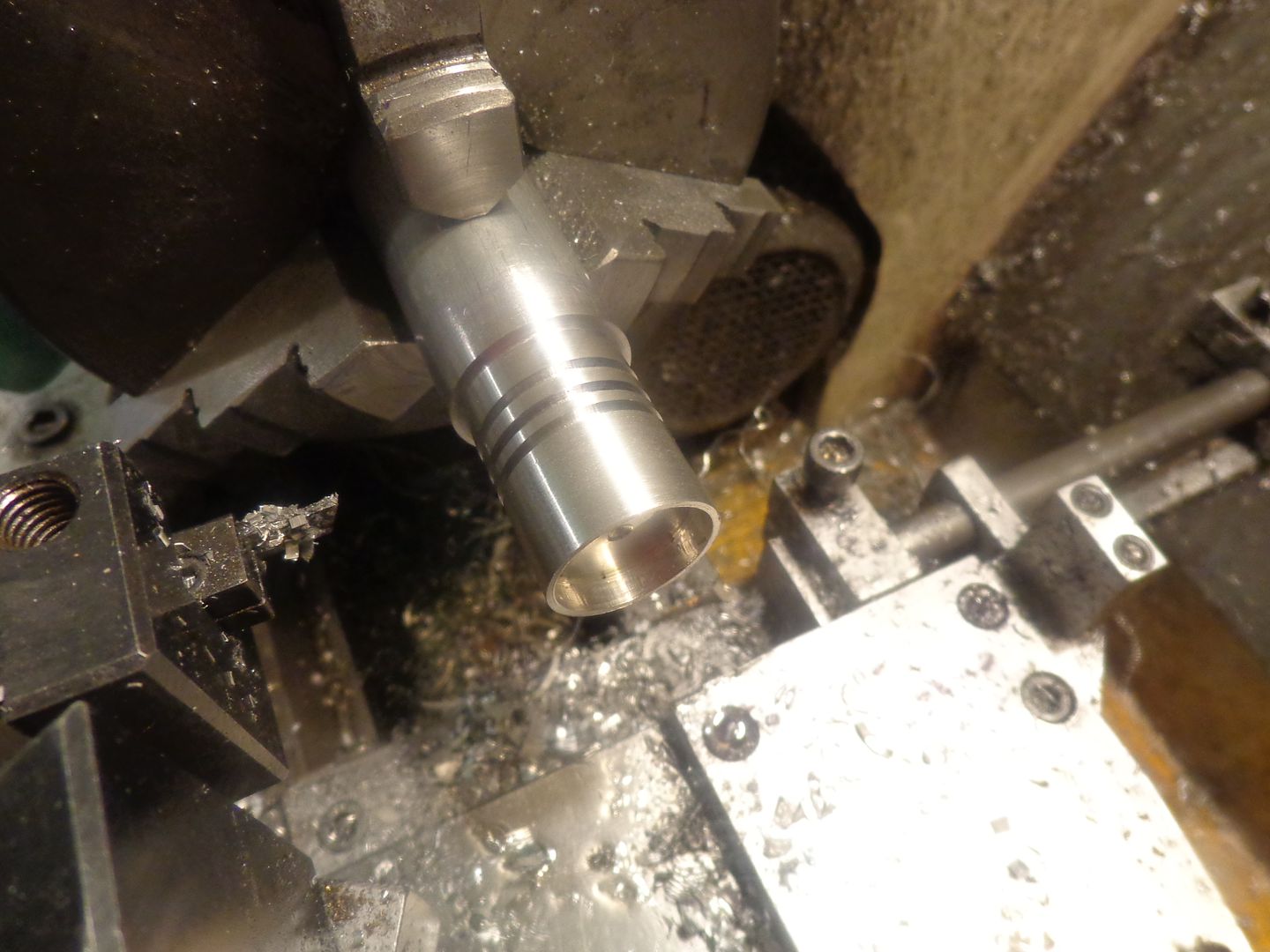
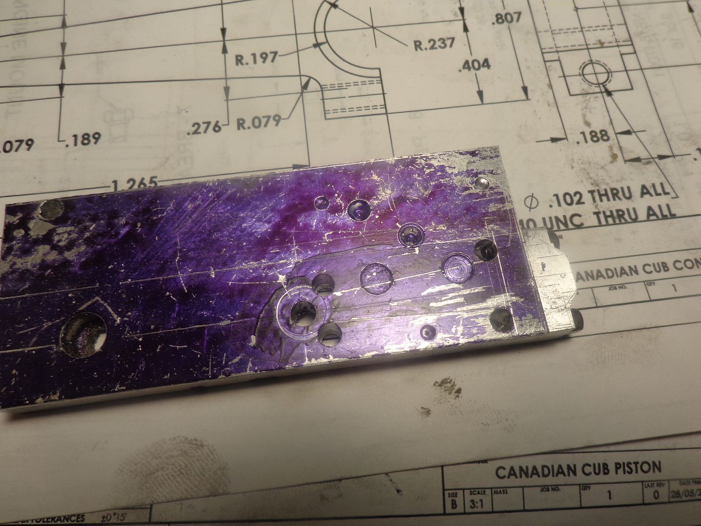
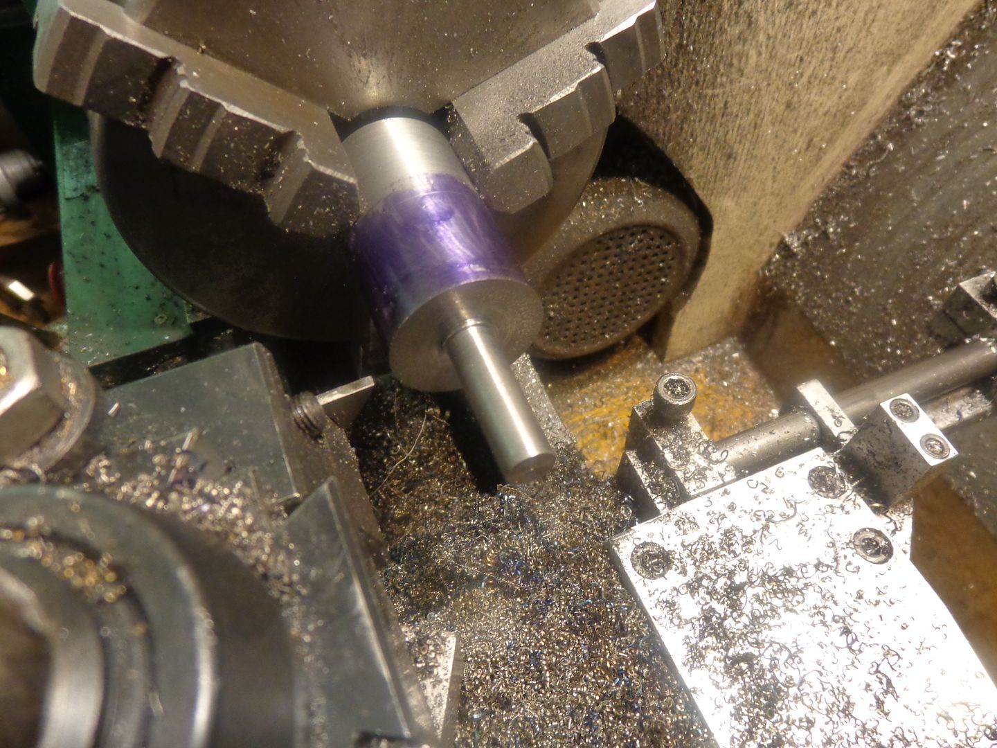
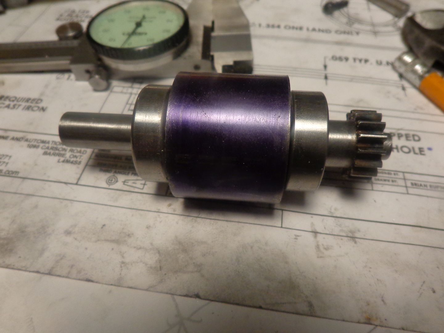
This is as far as I can go with the first stage of machining. A piece of 1" diameter aluminum is turned to 0.874" for sufficient length to get the piston length and about 1/4" more for cut-off tool allowance. The end is opened out to 0.787" diameter x .174" deep using a succession of drills, end mills, and finally a boring tool. The ring grooves are put in at this time also. In theory, a piston ring thickness is supposed to be 25 to 30 times less than the piston diameter. In reality, my thinnest parting off tool is .062", and that is about as fine as I am comfortable with when I have to part off the rings from a piece of cast iron. So---the rings will be just a couple of thou. less than .062" thick, and I am going to shoot for 1/16" square cross section on the rings themselves. you will see 3 grooves on the piston. The two nearest the end with the counterbore are ring grooves. The one farthest away from the counterbored end delineates where the length of the piston will be. In spite of all the good advice i have been given about parting off, my heart quails at the thought of trying to completely part the piston off from the main stock. I will now take it over to the saw, cut it off, then put the turned end into the lathe and face off the sawcut portion to line up with the groove already turned.

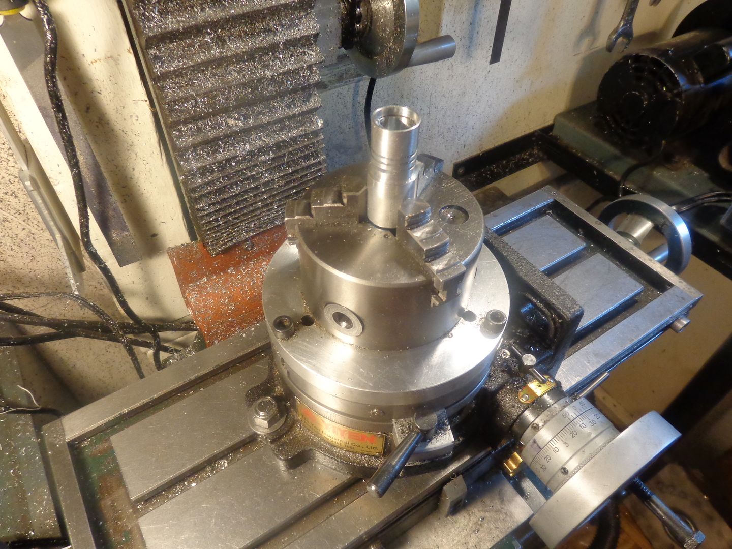
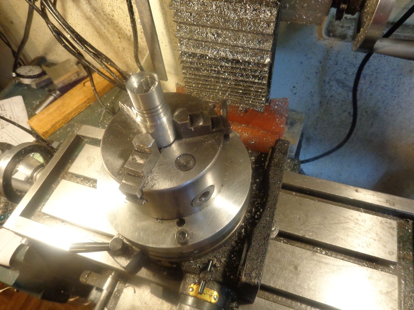
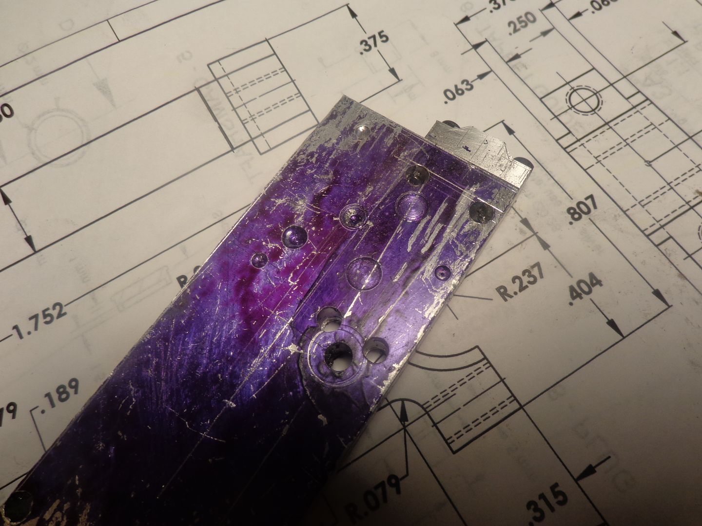
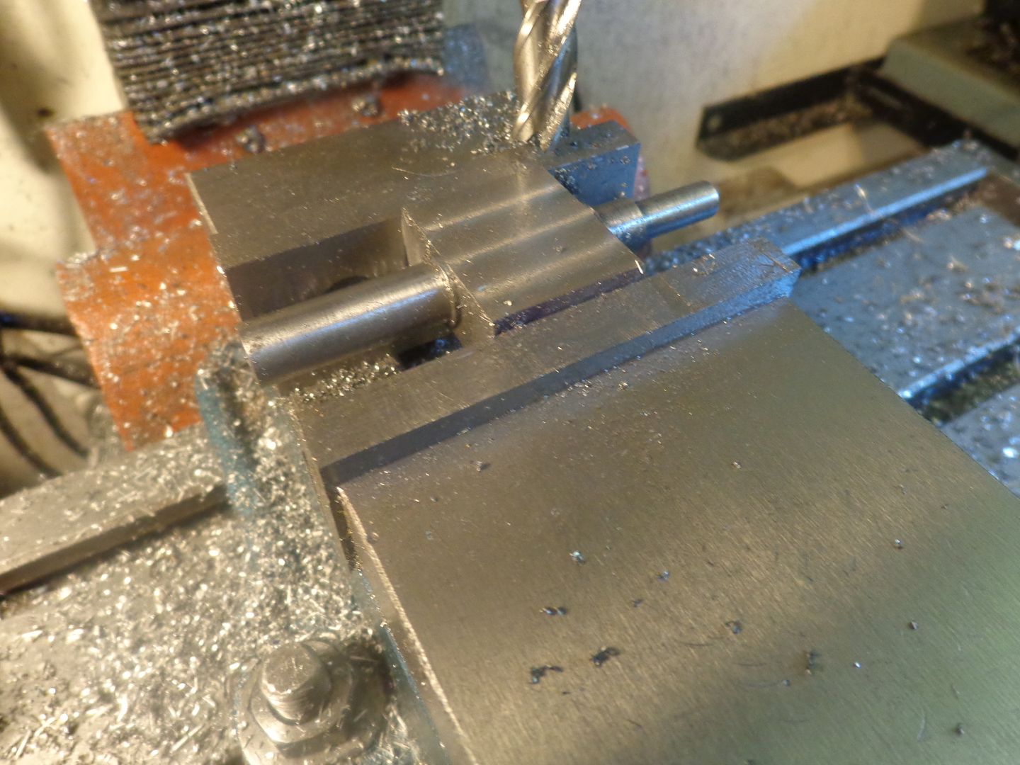
From the lathe we move over to the rotary table. The piston still hasn't been cut to length. It is about 2" longer than what the finished size will be. Set upright in the rotary table, and centered under the quill, the slot for the con rod is milled to depth. By milling the slot in the Y axis (away from you and towards you), this makes it very easy when I go to drill the gudgeon hole. My rotary table is locked so it can not rotate during these operations. By undoing the bolts which hold the rotary table to the milling table, I can flip the entire rotary table onto its other flat side, square it up to the mill table again, and then I am assured that when I drill/ream the gudgeon pin hole it will be at exactly 90 degrees to the long axis of the slot. I still have to drill and tap the set screw holes which hold the gudgeon pin in place before I tear down this current set-up to flip the rotary table 90 degrees.


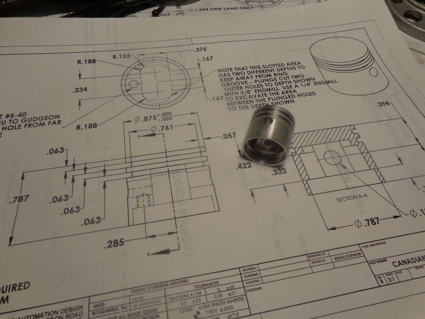
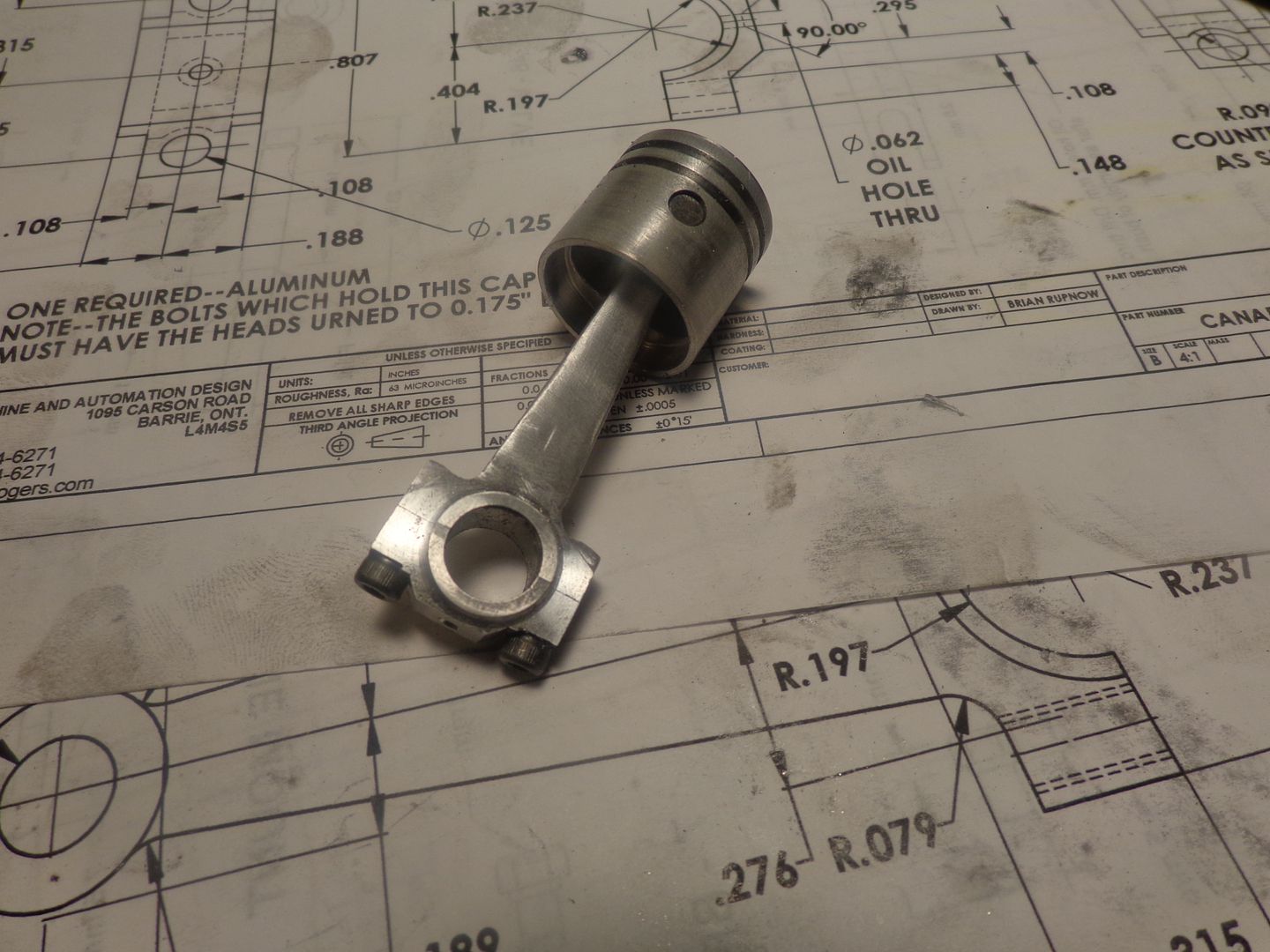
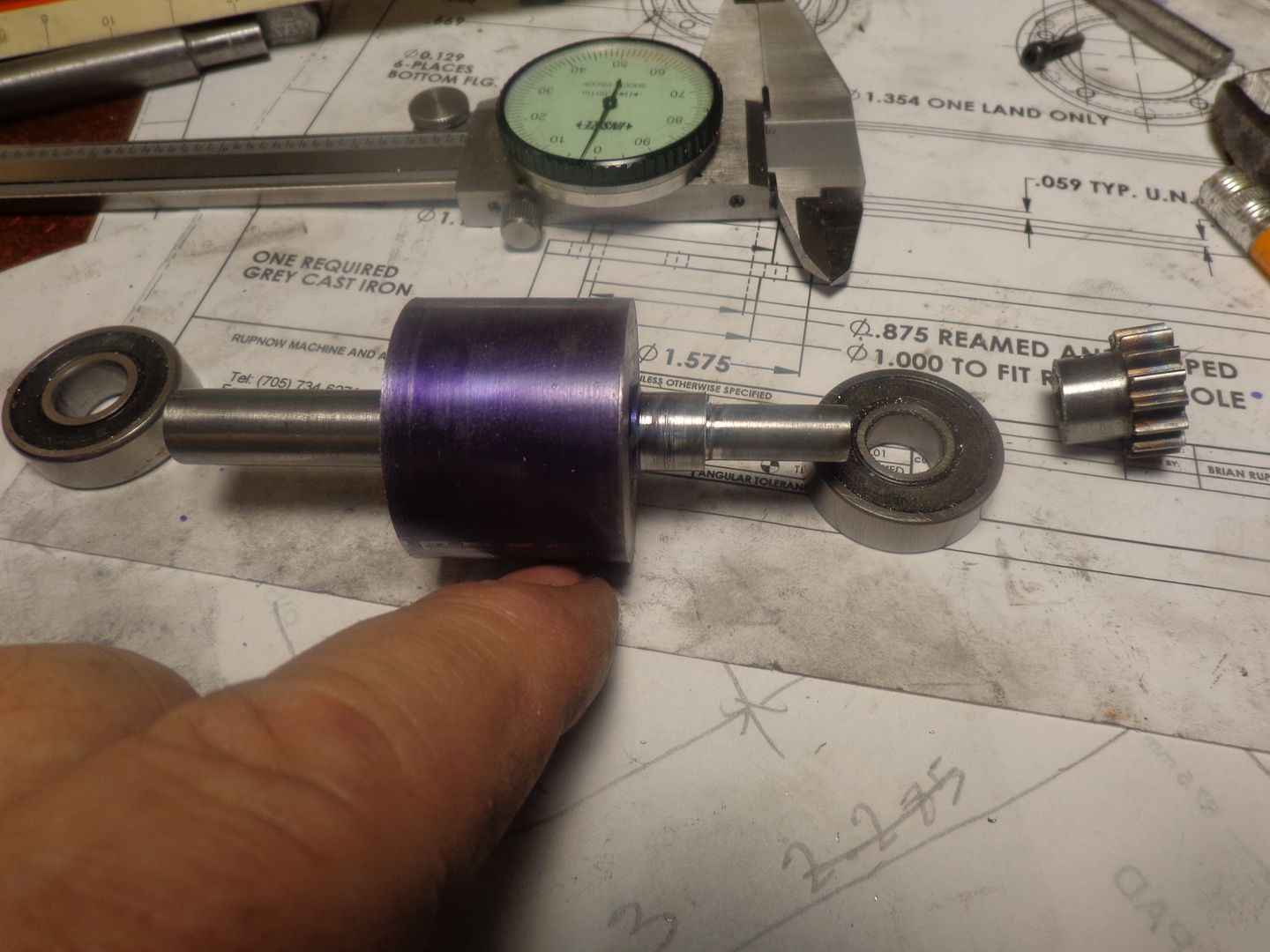
I didn't take any picture of the gudgeon pin hole being drilled. I do however have a finished piston. There is a little trick lurking in the bottom of that slot.--The slot is deeper in the center than it is at the outside edges, to keep the ends of the slot from breaking out into a ring groove.

Last edited:
I have just undertook a bit of research on making rings, and it seems I may have messed up when I made the piston. My grooves ended up being about 0.50" wide x .057" deep. There doesn't appear to be any issue with the width--The ring will be parted off at about .047 to .049" thick. Where the problem lies is with the depth of the grooves I made. The information I have says to make the blank from which the rings are cut about .003" to .004" larger in diameter than the bore of the cylinder (0.875"). The inner diameter of the blank should be a match for the inner diameter of the groove cut into the piston which would be .875"-(.057 + .057")=0.761". This means that the o.d. of the ring blank will be 0.878" and the i.d. will be 0.761", leaving a net thickness of .878-.761 divided by 2=.058" ring thickness from inner diameter to outer diameter. It seems (and I do mean seems) that instead of a thickness of .058, I should have aimed for about .040" (close to 1 millimeter). I have gone too far to turn back now, having just spent a goodly portion of the day making this piston. I am going to make up about 10 rings using the formula I have, and heat treat them using the method described by Malcolm Stride, who originally designed the Nemett Jaguar which i used as the basis for this engine design. If it works then all is good. If it doesn't work (the danger being that rings of this thickness are very prone to breaking when spreading them over the piston to install them in the grooves of the piston.) I will only be out some time. Neither the aluminum nor the cast iron left overs have cost me anything, and I am learning something new here. I will keep you all posted as this develops.---Brian
Okay--Today I have a tiny bit more insight, courtesy of Geo Britnell. He advocates turning the o.d. of the ring blank to .0005 more than the cylinder bore diameter. Even though my piston groove is 0.57" deep. George says to make the i.d of the ring blank .080" less than the blank o.d. This will give a ring approximately 0.040" or 1 mm thick. He said that having the piston groove deeper won't hurt anything, the rings will just "float" a bit more concentrically. Keep in mind that the rings get split, then wedged farther open at the split, then heat treated to take a "set" and then they have to be compressed to get them into the cylinder. Then the end gap of the ring is adjusted to about 0..002" to .003" with a diamond file. The fact that the ring is now only 1 mm thick lets it have enough springiness to install it over the piston and into the grooves without breaking the ring. John---As far as compression gasses getting in behind the ring and forcing it out against the cylinder wall goes, I am somewhat skeptical of this actually happening.
Last edited:
Today I will build the con rod and cap, if I can find enough material in my shorts rack. I may even get around to the piston rings.
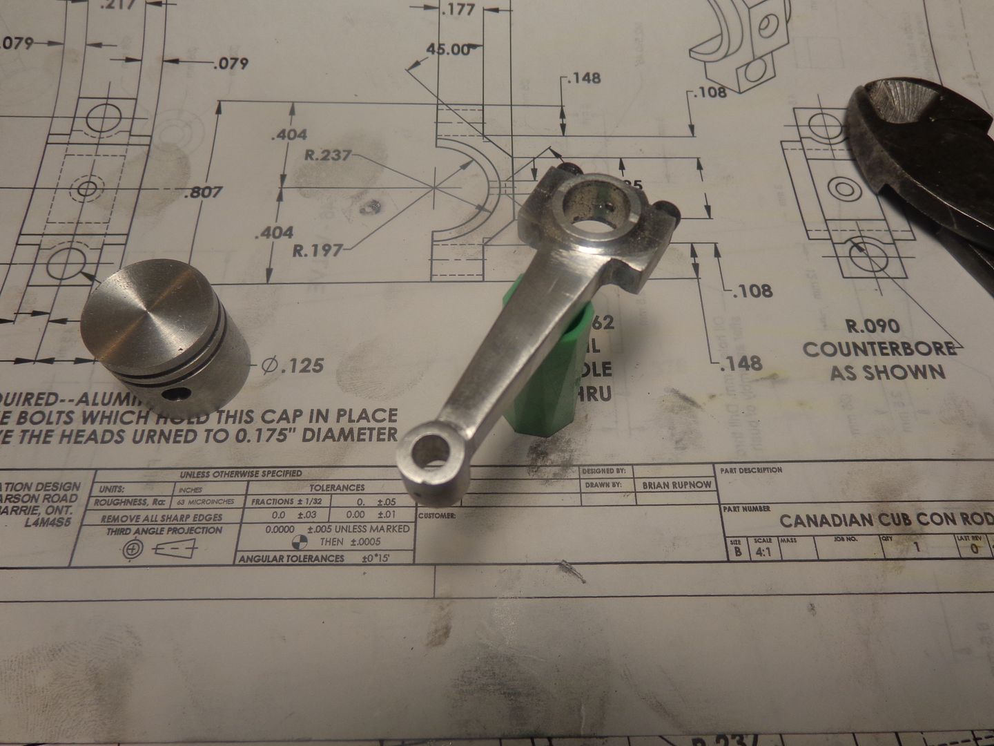
I hunted around in my "shorts" bin until I found a piece of 3/8" aluminum bar with a minimum number of shallow war wounds on it. I laid out the con rod and drilled the four diameter 0.158" holes to form the radii in the corners. I also drilled and reamed the 3/16" hole thru the small end of the con rod. I drilled and tapped the other end of the rod to receive the rod cap. I made up the rod cap as a separate part and drilled clearance holes, then bolted it to the big end of the rod. The next step from here is to drill and ream the big end hole, which will be half in the rod and half in the rod cap. Then I will fully cut out the outside profile of the rod and move to the next stage where I mill away 1/16" of material on each side of the rod, leaving only the bosses at both ends a full 3/8" wide.


Brian, I know it does not give materials on the drawing but that really wants to be HE15 or 2014 to you not whatever is in the scrap pile. That grade is the High tensile one that it says to use in the article
J
J
Last edited:
Jason--all of the aluminum I have is 6061 T6. Thats what I use for all my con rods, and other engine parts.
So--There we have it. A con rod and con rod cap finished. I must confess not to using the rotary table. It takes too long to get everything set up. I mill the flat on both sides of the rod in the milling vice, staying about 1/16" away from where the radiused ends are. Then I turn a spigot of material .001" larger than the big end bore and clamp the rod to it. The lathe makes short work of putting a radius on the big end. Do one side, then flip it around and do the other side. For the small end I do the outside of the radius on my belt sander, except where the body of the rod is in the way. Loctite a piece of 3/16" crs into the bore, letting it stick out about 1" each side. Then I drill the oil hole in the small end and drill right on into the 3/16 cold rolled. Then Loctite a short piece of 1/16 crs into that hole so it locks the 3/16" into place. Then I turn the small end in the lathe the same way. After 5 minutes with a small file and some fine sandpaper, I'm finished. It might not be jewelry quality, but it is dimensionally correct and will be hidden inside a crankcase.


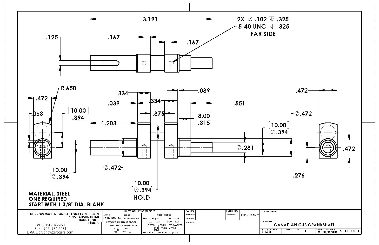
Good morning, Guys and Gals.--I woke up feeling rather cranky this morning, so decided it would only be appropriate to make a start on the crankshaft!!! I am going to turn the crankshaft from solid, using a new method that I first seen used by Gail in New Mexico on his original opposed piston engine. I will also be trying out 1144 stress proof steel for the first time. Stay tuned. You may learn something new, or, at the very least have a chance to laugh and call me the Canadian Pretzel maker.----Brian


Last edited:
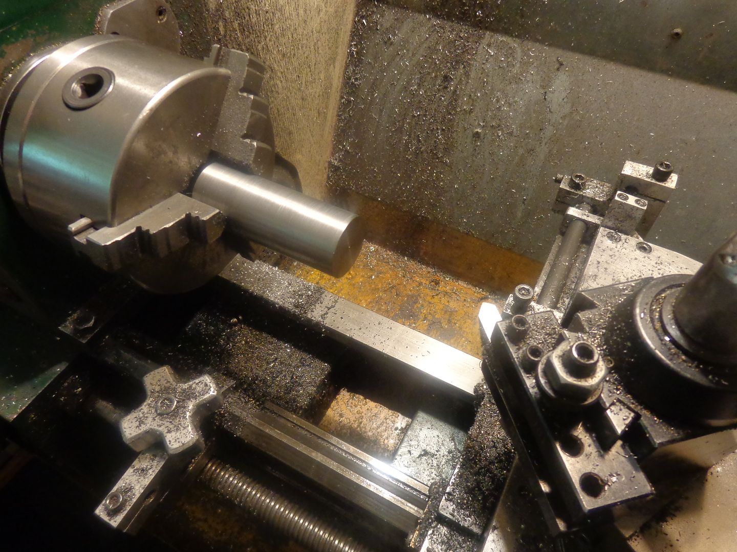
First step was to cut off a length of 1 3/8" diameter stock about 1/8" longer than the overall crankshaft length, face both ends, and turn the outer diameter to an exact 1.300" diameter. Next step is to completely finish turning one end (in this case the end without the reduced diameter for the timing gear) and to make sure I had the .039" x .472 diameter boss turned as well. There is really too much material sticking out past the chuck jaws, which makes things want to chatter. I was using a carbide at 920 rpm, taking .005 deep radial cuts. When I got close to finished diameter I backed off the depth of cut to .002 radial, which got rid of the chatter, turned the part until it was .002" oversize, then finished to size with #180 and #220 grit emery cloth. That is a lot of material to leave on, which means shutting off the lathe every 20 passes with the paper and trying the bearing to see if it fits yet. I don't trust myself nor my machine to turn the diameter to finished size. Bitter experience has taught me to leave some material on and remove it with emery cloth. Its a time consuming pain in the keester, but I don't ruin parts by turning them undersize.


Last edited:
The crankshaft is now completely turned at both ends. People were right---the 1144 stress-proof steel is nice to work with. I haven't done anything yet to actually make the crankshaft bend out of "true", but that step will be next. The extra bit of shaft which sticks out past the gear will get trimmed off flush with the face of the gear.


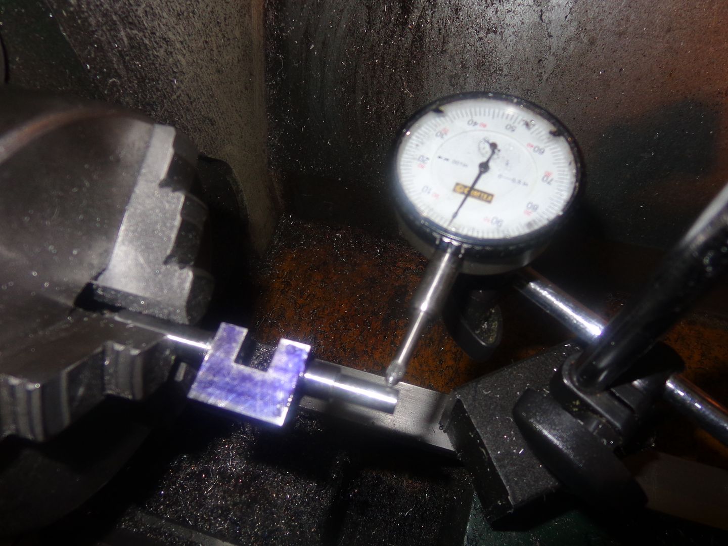
Now this is where it begins to get ahh--Exciting!!! The crankshaft is set up on parallels in the milling vice and one side is milled away, right down to the .472" diameter boss. Then it is flipped over, again rested on parallels and machined down to the .472" diameter boss again. --I did cut away most of the metal to be removed on the bandsaw before setting up in the mill. Now---How much did the crankshaft twist out of true when I took this big slab of each side?----good Question. My 3 jaw chuck is about .003" total indicated runout out of center. (That is true out of center by .0015) I held one end of the crank in the 3 jaw chuck and indicated the opposite end while rotating the chuck thru 360 degrees, and got a reading of .010" TIR which is about .005" out of true center. This doesn't concern me much. I have learned that these damn small crankshafts are like a piece of spaghetti. Once all the cutting is done, I will hold one end in the chuck and tap the other end around with my dead blow hammer (little taps) until it moves into a "zero" run out position.
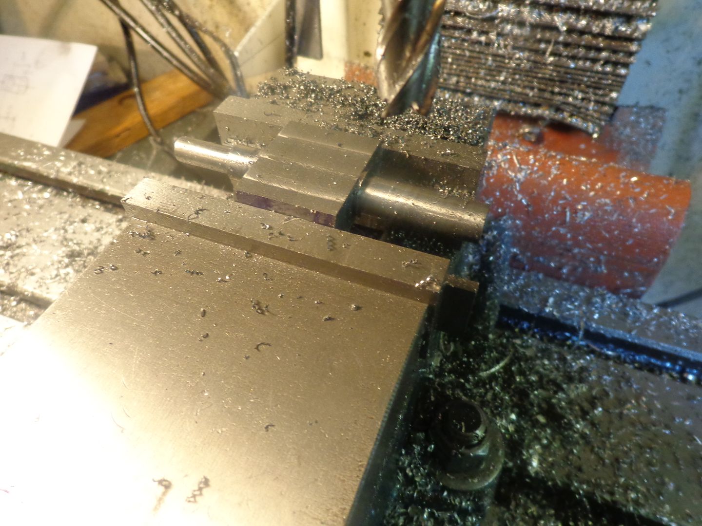


The crankshaft is now machined as much as it can be, until I build the crankshaft turning fixture. The total indicated runout is now up to .013 TIR.as measured in the picture. After I make the turning fixture, and do the final cut on the rod journal portion of the crankshaft and tap two holes for the counterweights, then I will get out my trusty deadblow hammer and "straighten" the crank.
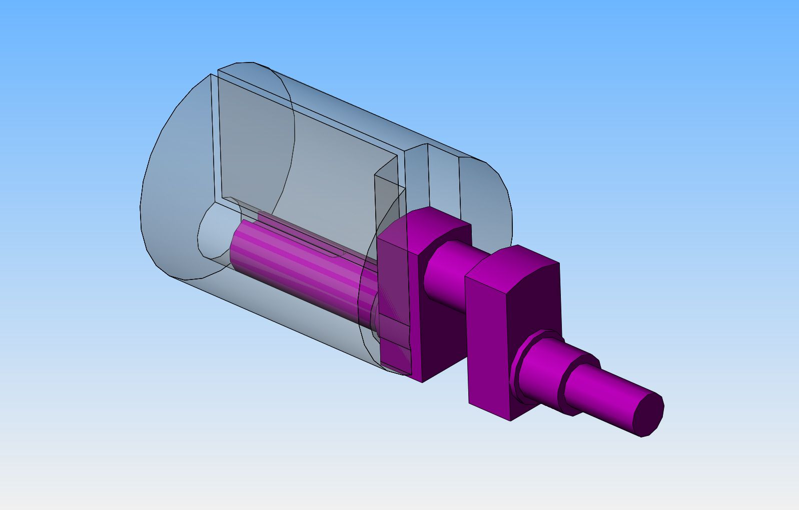


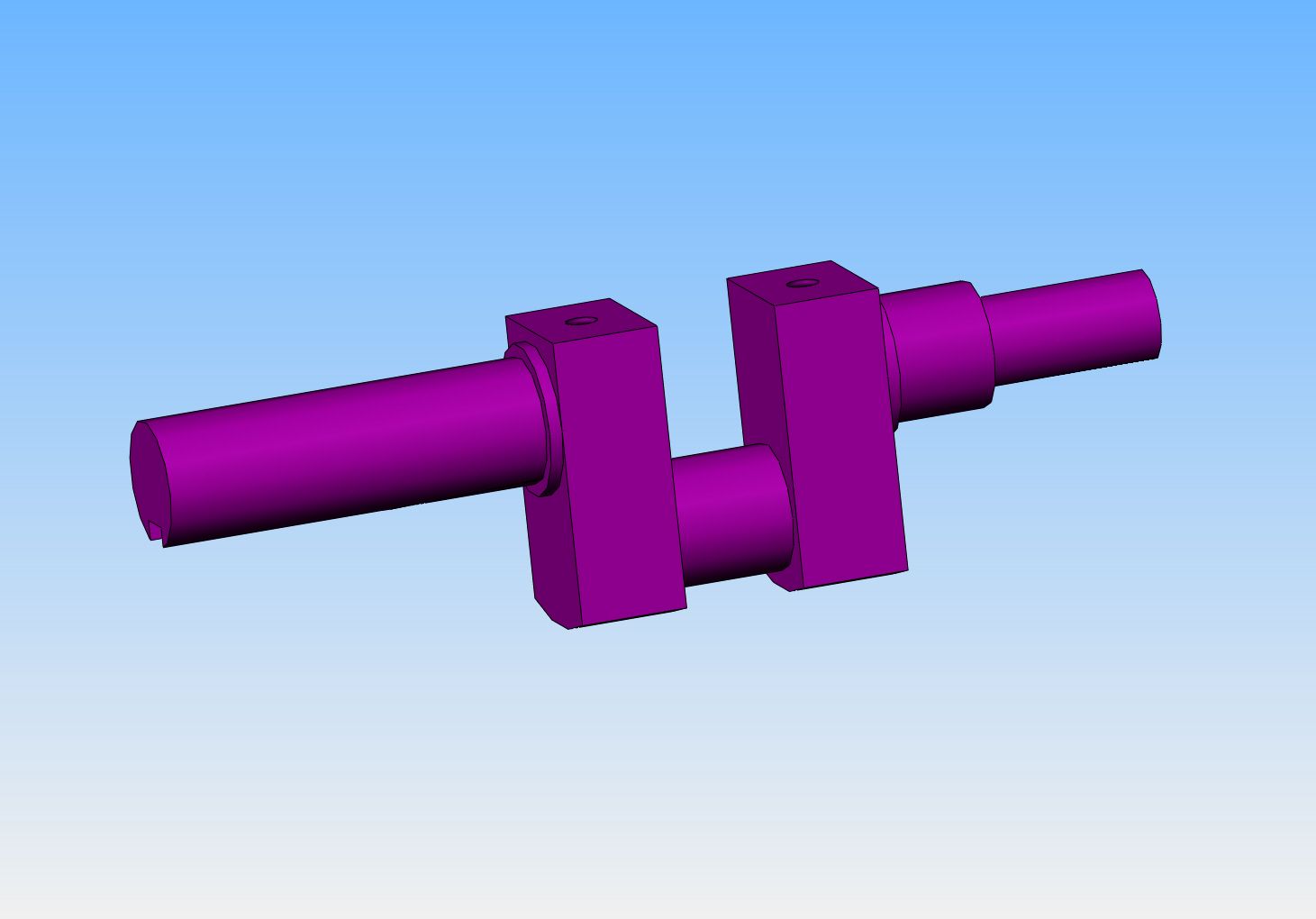
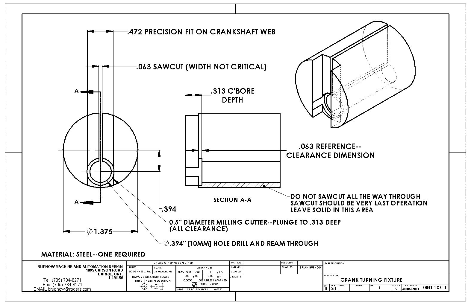
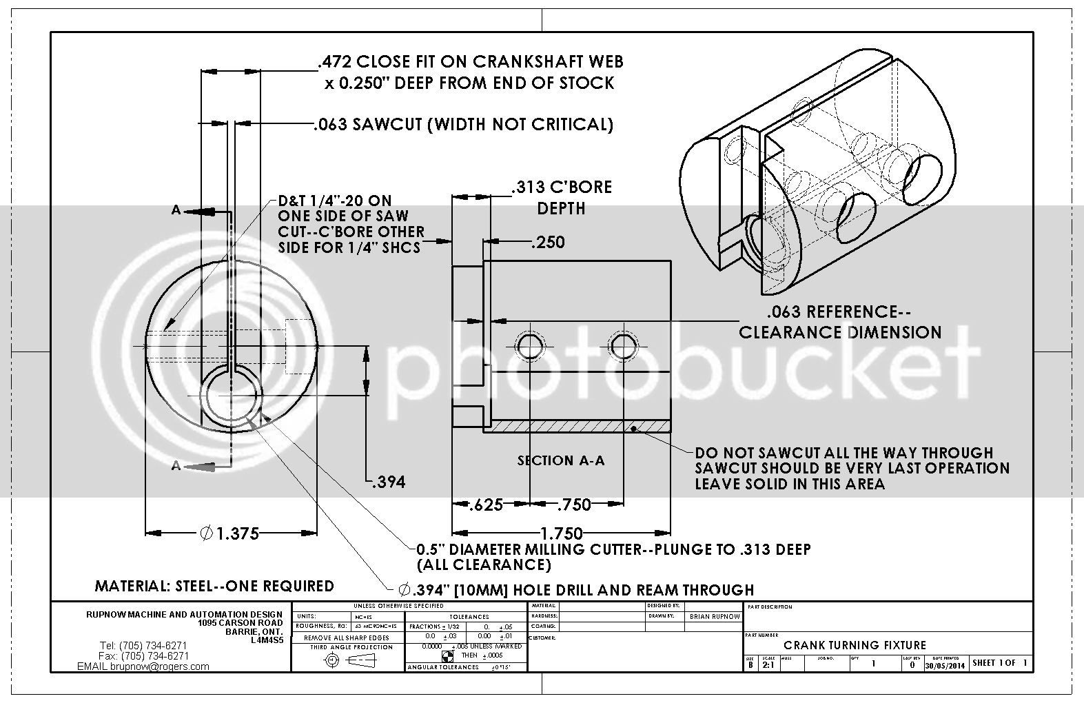
For those who are interested, this is what the crankshaft turning fixture looks like. It will have to be drilled and reamed in the 4 jaw chuck in my lathe. It could also be done on the mill, but I wouldn't be able to really guarantee that the center of the drilled and reamed hole would be parallel to the central axis of the main outer diameter, and that is quite critical.

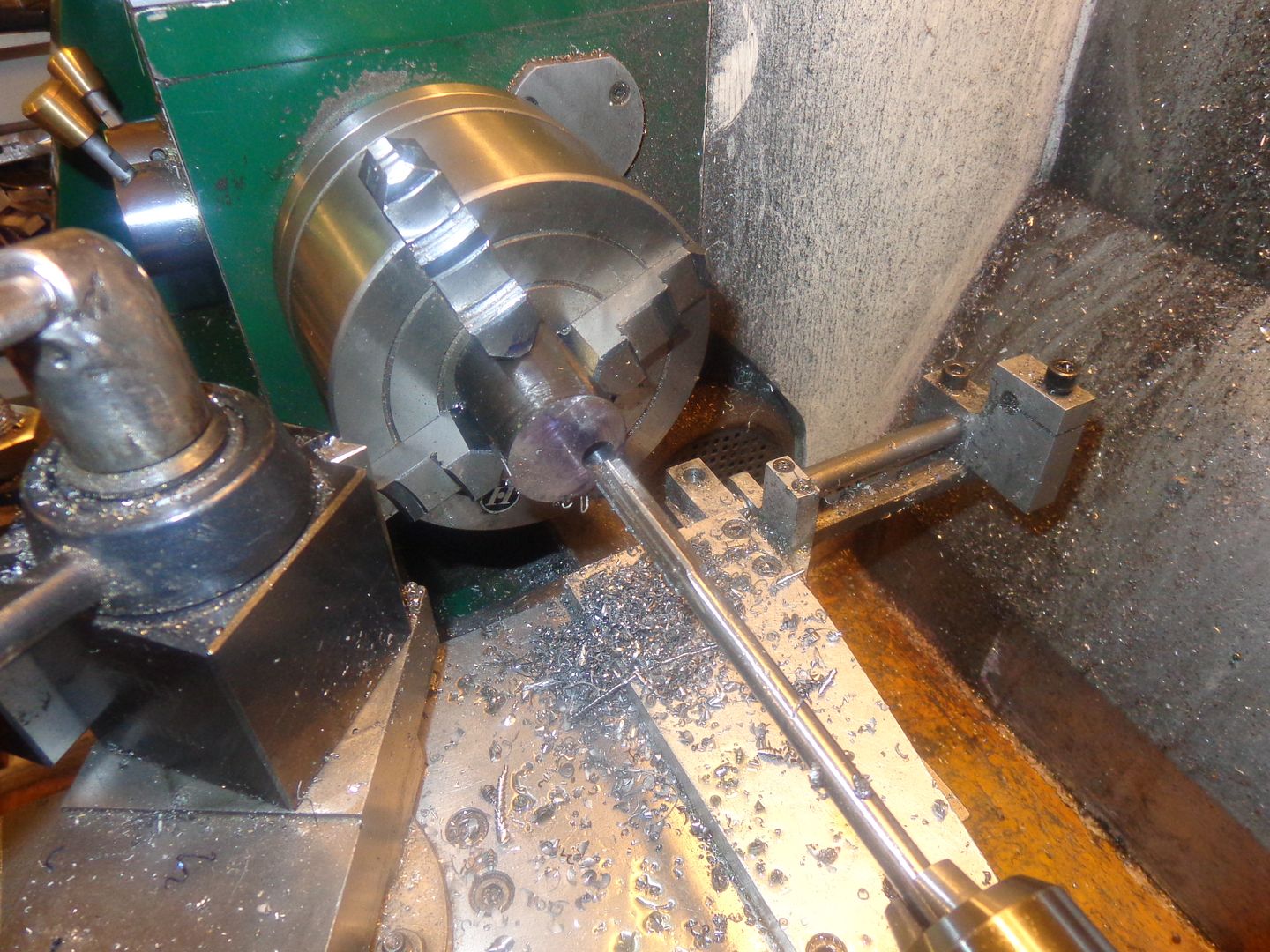
So--I am about to ride off--to the couch and a drink of wine!! As far as I know everything I have done today has went extremely well. Of course the fat lady won't sing until tomorrow when I get the crankshaft and jig set up in the lathe and turn the rod journal. I will leave you now with this loverly picture of my jig in the 4 jaw chuck. I hate setting up that 4 jaw worse than snakes, but it certainly does the job well. I have since finished the jig all except for the sawcut, which will happen tomorrow. Thanks for looking.---Brian

I have rethought this crankshaft turning fixture a little bit. I have a lot of work into it, and there is only a very thin web of material left holding the two sides together after the sawcut is put in. As a safety measure, and to aid in clamping the crankshaft, I have added provision for two 1/4" socket head capscrews. If you make one, just make sure the counterbores are deep enough to totally bury the head of the capscrew, because this thing has to go back into my 3 jaw chuck to turn the con rod journal on the crankshaft.

- Joined
- May 27, 2010
- Messages
- 2,999
- Reaction score
- 1,171
I have rethought this crankshaft turning fixture a little bit. I have a lot of work into it, and there is only a very thin web of material left holding the two sides together after the sawcut is put in. As a safety measure, and to aid in clamping the crankshaft, I have added provision for two 1/4" socket head capscrews. If you make one, just make sure the counterbores are deep enough to totally bury the head of the capscrew, because this thing has to go back into my 3 jaw chuck to turn the con rod journal on the crankshaft.
Hi Brian,
Will use this jig to machine crankshaft for Jaguar in 2015. The Lynx and other mini projects will keep me busy for the rest of 2014. Thanks for drawing.
Similar threads
- Replies
- 0
- Views
- 2K
Latest posts
-
-

-

-
-
 For Sale Perkins Vertical Side Shaft Casting kit
- Latest: hopperwhistle
-
Sold Full Scale Creators Popcorn Steam Engine Kit
- Latest: hopperwhistle
-
-

-
For Sale 1/3 Scale Galloway Hit and Miss Casting Kit
- Latest: hopperwhistle