Nemett Jaguar--Canadian style

Home Model Engine Machinist Forum

Help Support Home Model Engine Machinist Forum:

This site may earn a commission from merchant affiliate links, including eBay, Amazon, and others.
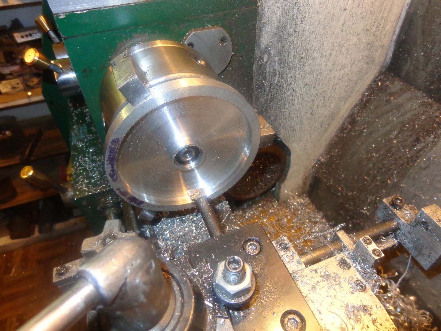
I really wasn't sure how to make this part. It could have been done any number of ways, but the lathe removes material so much faster than the mill that I decided to take a lathe approach. I started with a 6" square piece of 1/2" aluminum plate, scribed a circle on it larger than the largest dimension I would need from the center to the extreme outside edge of the finished part, roughed it out on the bandsaw, then used the old sticky tape trick to true it perfectly round. I then reversed the jaws in my lathe, gripped the plate, and used my home brewed trepanning tool to chew most of the unwanted material out of the center, then used a left hand carbide in the toolholder to finish the bottom of the excavation nicely and turn the O.D. of the spigot to a nice 1.181" diameter. I then drilled out the center in progressive steps up to 31/32" and finished up with a boring tool to get the exact bearing diameter. Tomorrow I will remove the outer rim with my bandsaw and finish the profile of the plate.

 
Gus, if you do the bore first in the lathe, this removes a lot of material, see my build.

By the way, if you end up in Dandenong with your excavation, you will miss me, I live in Mount Martha.:)

Paul.

Tunnel done and access shaft to ground level done too but now lost at Dandenong. Never thought I would see day light. Been nailing biting,milling
crankcase on a mini mill. Quite happy with the accomplished task.:cool:
 
Sometimes when I have an odd shaped part, with many holes to be drilled and no good "witness" edges to do my layout from, I print out the part at 1:1 scale, and find a starting point (in this case the bearing hole). I drilled a couple of the #4-40 threaded holes as far as I could get from the center hole, then located the paper layout (glued to a cardboard backing) using one cap screw and one drill of the correct size. I still used ordinate dimensions and the dials on my mill to locate all the holes yet to be drilled, but I had a good visual reference to confirm that yes, I had counted the correct number of dial revolutions and the holes were going to be where I intended them to be. You will see one area close to the large hole where there are two holes drilled that weren't marked on the drawing, and one hole marked on the drawing that isn't drilled. That is not a mistake. It is the result of a small design change after I had cut out and glued the drawing to the cardboard.
 
The other really great thing about an accurate 1:1 printout glued to cardboard, is that after all of the drilling is finished, you can remove the print, color the metal with layout dye, wait 5 minutes and then put the cardboard back in place and scribe around it.--Then, presto---You have al the outer profile to cut to. since it is only a profile and not critical really, saw close to the scribed line on the bandsaw and then file to finished size.

 
And we end up with a quite nicely executed timing baseplate!! I will now use the outer profile of this part to scribe an outline on a rather nice piece of bronze plate, which will become the actual gear cover.

 
And we end up with a quite nicely executed timing baseplate!! I will now use the outer profile of this part to scribe an outline on a rather nice piece of bronze plate, which will become the actual gear cover.


Cheers to WW-1 and 2014 technology. Planning to build the single cylinder engine in 2015. This is great idea. th_wav
 
Today was a gorgeous day.--It felt like summer for the first time this year.--No clouds, high of 28C (about 86F) ---God, I loved it. Took good wife for a drive in the country and out to Creemore for lunch. (Creemore has a micro-brewery that makes amazing beer.) The rest of the day I whittled away at the crankcase, boring holes for camshaft bearings and timing gear baseplate. All the holes lined up, which is always a GOOD thing. Here is a picture of the timing baseplate bolted to the crankcase with all of the gears dummied into position.

 
Looking good. I can almost hear this engine running.

2015 will build this engine. The Lynx Engine will take some time------at least two months. Learned no to rush. Do it right the first time.

On my part,I am working on the un-ending small details.
 
Nice work on that baseplate, Brian.

Chuck
 
Many good things happened today!! The other side of the crankcase got bored and the bearing holder inserted. The machined bearing cap which covers the camshaft bearing on the non gearcase side was installed--not Loctited yet, but it fits in very nicely. I didn't have any 4 MM shaft to make the camshaft from, but I turned a piece of 3/16" rod to 0.157" which is 4 mm and made the camshaft and installed it along with its bearings into the crankcase. (The cams get made as separate pieces and attached to the camshaft at a later date). The camshaft bearings which I reclaimed from my first build of the Atkinson were 5 mm so I made up combination cam spacers/ bushings to match the 4 mm camshaft to the 5mm bearings. I made up the pedestal support for the idler gear and installed it, and after assembling all of the gears, Hallelujah--they mesh just fine. As you can see by the pictures, I have to shorten up my bolts and trim some off of the inside edge of the main bearing housings--(they should end flush with the inside of the crankcase. All in all, a very satisfying day!!


Brian, won't you also need to bore the bearing hole deeper so the bearing also sits flush with the case insides or did the sides come out a bit thinner?
 
Jason--You are absolutely correct. The bearing holding plates on both sides of the crankcase were both machined from 1/2" plate, and not trimmed to length when the pictures were taken. I measured out how far they extended in past the inner walls of the crank-case this morning and shortened them both up by the amount required to bring them flush on the inside. I did have to deepen the counterbored bearing pocket in the non-timing gear side to bring the bearing into its proper position as well.
 
There was a whole lot of breath holding and finger crossing going on at my house this morning. I put all of the cosmetic chamfers and indentations in the crankcase. These are a feature which add absolutely no value to the way the engine will perform, but are for "pretty". This is usually the point at which something jams, lets go, or plain screws up on a part that has a ton of work already done correctly on it, and destroys the part. However, I seem to have escaped unscathed, and the only real machining left on this part is the hole pattern in the bottom that the oil sump attaches to and an oil filler hole.


I still have to do a bit of creative carving, deepening counterbores, etcetera, but by and large the overall "body" of this engine is complete except for the gear cover. For one horrible moment I thought I had reversed a bolt pattern in the top of the cylinder, but then realized that the bolt pattern at the bottom of the cylinder lets me rotate the entire cylinder 180 degrees, and thats what I had done. A quick disassembly and reassembly of the cylinder and crankcase got my heart slowed down again.

 
Looking very nice Brian, you are certainly correct about having to be careful when you have put a large amount of work into an item. It would be a shame to make a mistake on a part that you have sweated over for days.

Paul.
 
I think that is a syndrome known as "Model machinists angst."---The more work you put into a part, the more you are concerned about screwing it up. --Brian
 
Today I bit the bullet and ordered a 36" x 60" ergonomic rubber mat to stand on. The stool just doesn't cut it. I'm in and out between my little machine shop and my computer about 50 times a day, and every damn time I turn around the stool was in my way. I could actually work while seated on it, but I have come to realize that hardly any of the machining I do is constant machining. I'm up and down, in and out more times than I ever realized.
 
I think that is a syndrome known as "Model machinists angst."---The more work you put into a part, the more you are concerned about screwing it up. --Brian

Hi Brian,
I share this ingrained fear with you. The Nemett-Lynx crankcase has 8 more M3
thread holes to do. The Bearing housing have one bearing to fit in.
To counter the ''Jinx'', I take many tea/pee breaks.

Good Luck.
Take care.
 
Today I think I will do one of the easiest, but most vital parts of an engine---the piston. I have been really "pouring it on" in my little shop, but today I want something quick and easy to machine. I have always subscribed to the "cast iron piston in a cast iron liner" theory. but Malcolm Stride uses an aluminum piston in a cast iron liner and seemingly gets away with it. He does say to leave the piston diameter about .002" smaller than the i.d. of the cylinder to keep from having problems with piston expanding and seizing in the bore.-I have been taught to never use this combination, but this time I will try it and see what happens.
 
Last edited:
Back
Top