Petertha--I haven't got that far yet, but will today. In all probability, the shaft centers will remain the same and only the idler position change. I will know by the end of today. This engine, at 6:1 compression ratio will run on either conventional spark ignition or on glow plugs and methanol.----Brian
You are using an out of date browser. It may not display this or other websites correctly.
You should upgrade or use an alternative browser.
You should upgrade or use an alternative browser.
Nemett Jaguar--Canadian style
- Thread starter Brian Rupnow
- Start date

Help Support Home Model Engine Machinist Forum:
This site may earn a commission from merchant affiliate
links, including eBay, Amazon, and others.
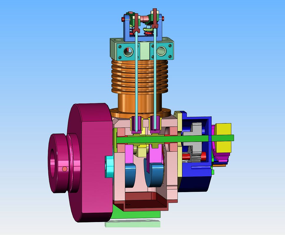
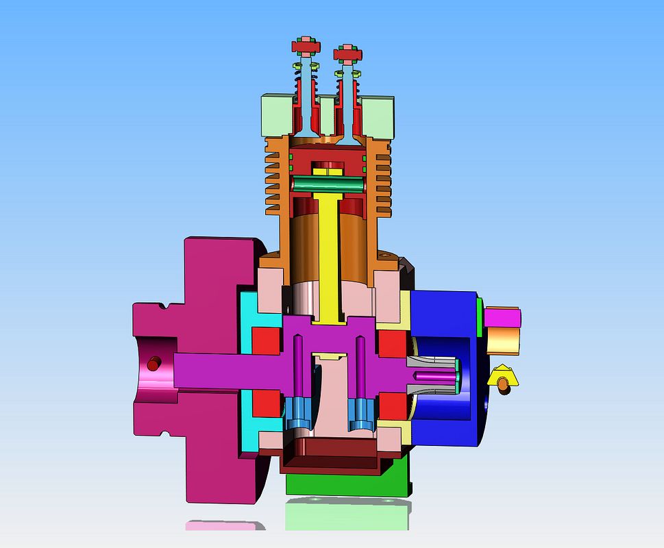
Okay--There is a lot going on here, some you can see, some you can't. The original cam bearings called for were 4mm i.d. x 12mm o.d. x 4mm thick. I had a pair of new bearings left over from my Atkinson build that were 5 i.d. x 16 o.d. x 5 thick. I bored out the outer case to accept them and monkeyed with the cam spacers at each end to have an extension that slid into the bore of the bearings to make up the difference between the 4mm shaft and the 5 mm bearing bore. The green cam shaft cap had to grow from 12mm dia. to 16nn dia., and now it sets in flush with the outer side of the main housing to prevent fouling the main bearing support (that will show up better in the next post.) The cam shaft is extended out through the gear case and that yellow thing on the right hand end of the cam is the ignition cam. I have to put a hole in that case for the shaft to pass through, and an oil seal. I wanted to make the camshaft something in imperial, but there is no close conversion to get a 4mm shaft into imperial. 1/8" is too small and 3/16" shaft (4.762mm) would have been too large to allow a proper spacer inside my 5mm bearings, so I left the shaft at 4mm dia.

Last edited:
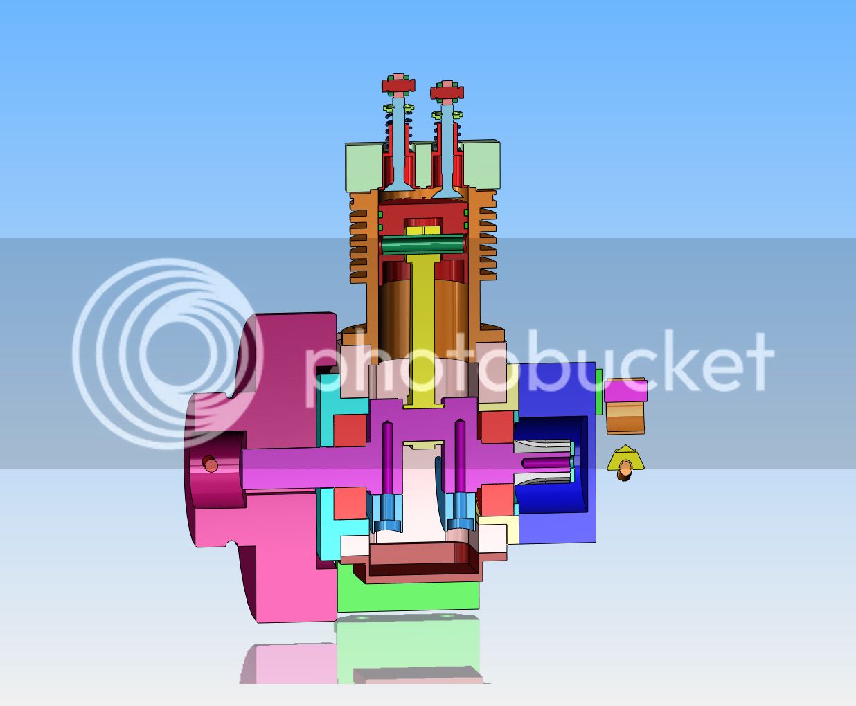
More interesting stuff happening here. The original plans had two different sizes of crankshaft bearings, a 12mm on one side and a 10mm on the other side, plus an additional bearing at the outboard end of the bolt on bearing support to help support the weight of a propeller. I had a pair of 10mm bearings, so have eliminated the third bearing and went with a 10mm brg on each side of the crankshaft.The light blue bolt on bearing support has become much shorter and tucks in tight to the side of the main crankcase so that the new flywheel basically fits right over top of it. It had to grow in diameter to suit my 10mm bearings which have a larger outer diameter then the original bearings which were called for, so actually overlaps the cam shaft cap---That is why the cam shaft cap now sets in flush with the outside of the main crankcase. The cast iron liner has been eliminated. The cylinder is now cast iron instead of aluminum and has now been given a 7/8" bore, with an extension piece which extends below and above the original cylinder bottom and top faces to end where the cast liner originally ended. The gudgeon pin and cylinder cross bore have changed to 3/16" diameter. The piston is now 7/8" diameter and the crown area has been thickened up. The ring grooves, rings, and cylinder grooves have all changed to 1.5 mm because that is the width of parting off tool that I have. The flywheel is much larger in diameter than the original, and the support feet have been extended to give adequate backing so that the flywheel doesn't hit the table. The bolts which secure these bolt on angles to the sides of the crankcase have been moved down considerably in the crank case sides. The cylinder head, valves, and rocker arms are basically unchanged.

Last edited:
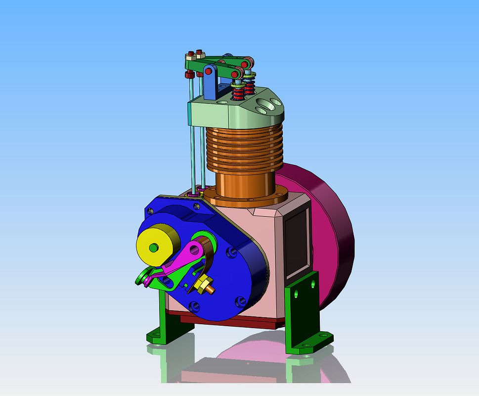
The timing gear cover has underwent a shape change and is squared off at the top to match the squarish profile of the main crankcase. It has also been widened in critical areas to act as a base for my standard Chrysler ignition points. I now have to change the gears from metric mod style to 24DP to match the cutters that I have and hope that I can fit them into the "existing" gear cover.

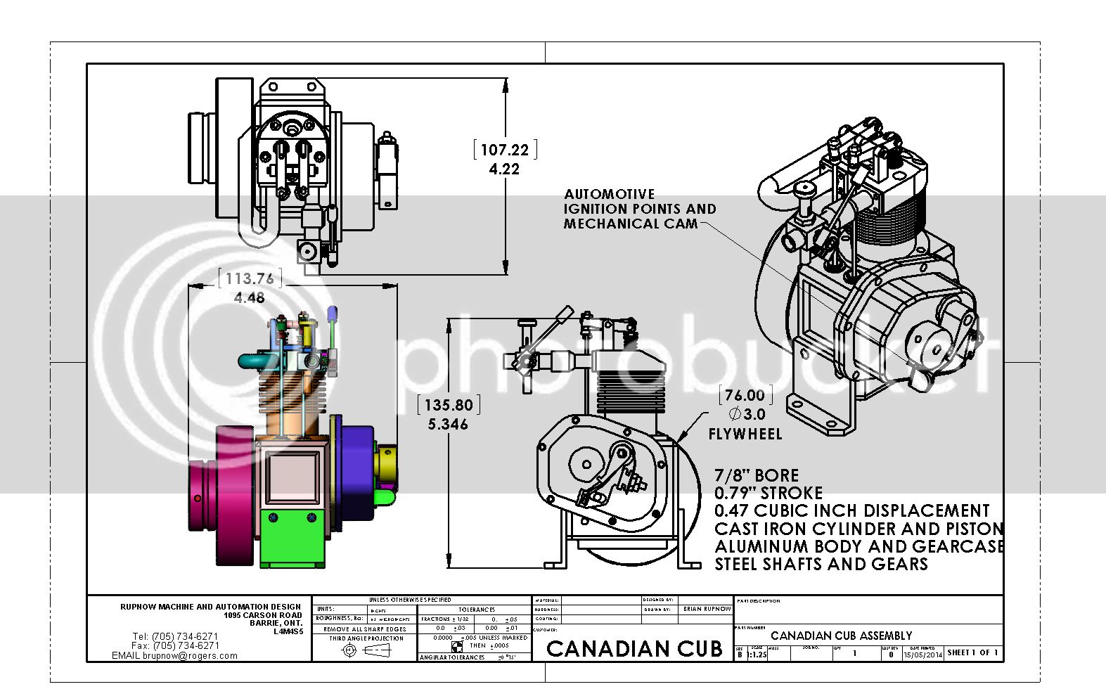
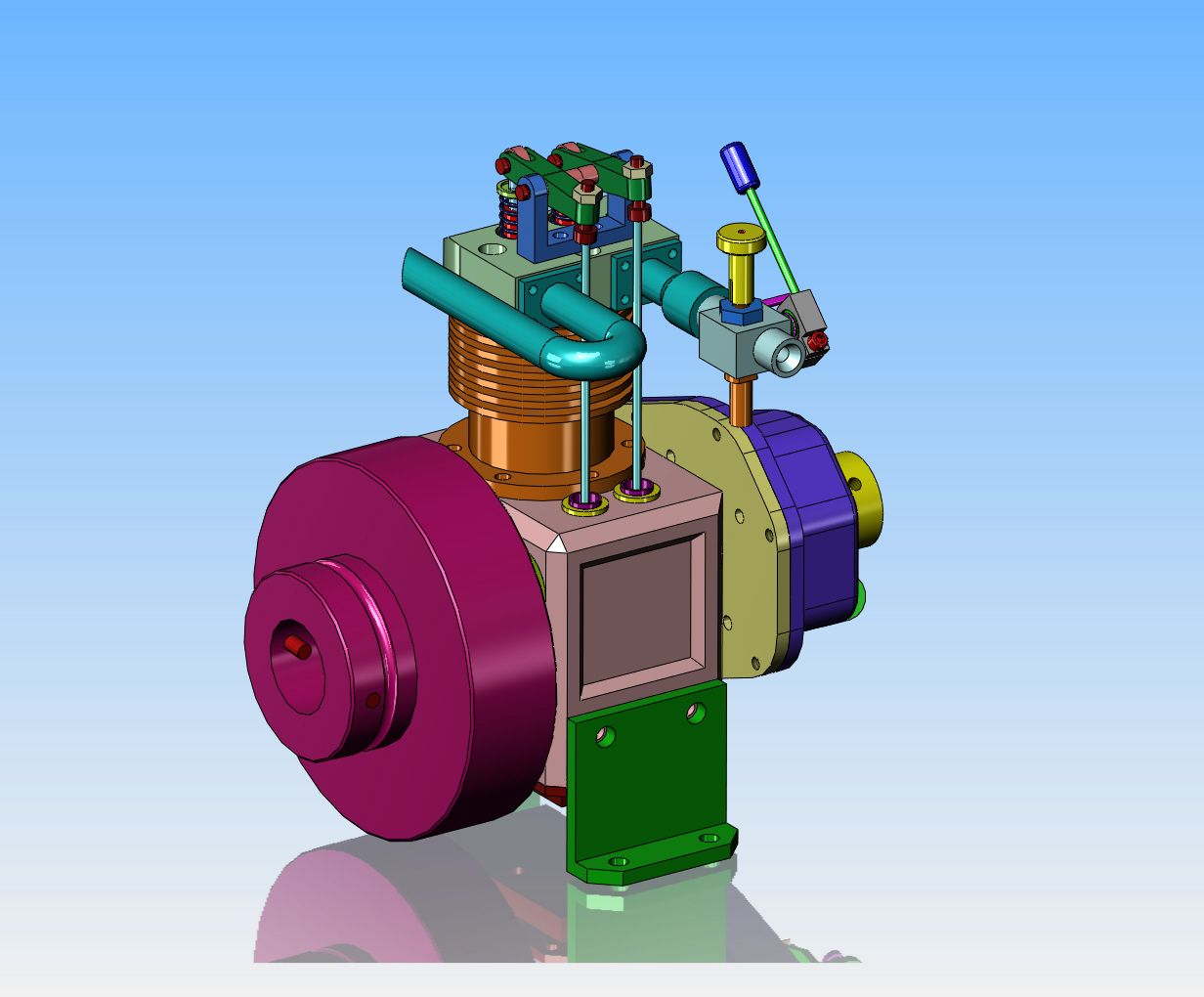
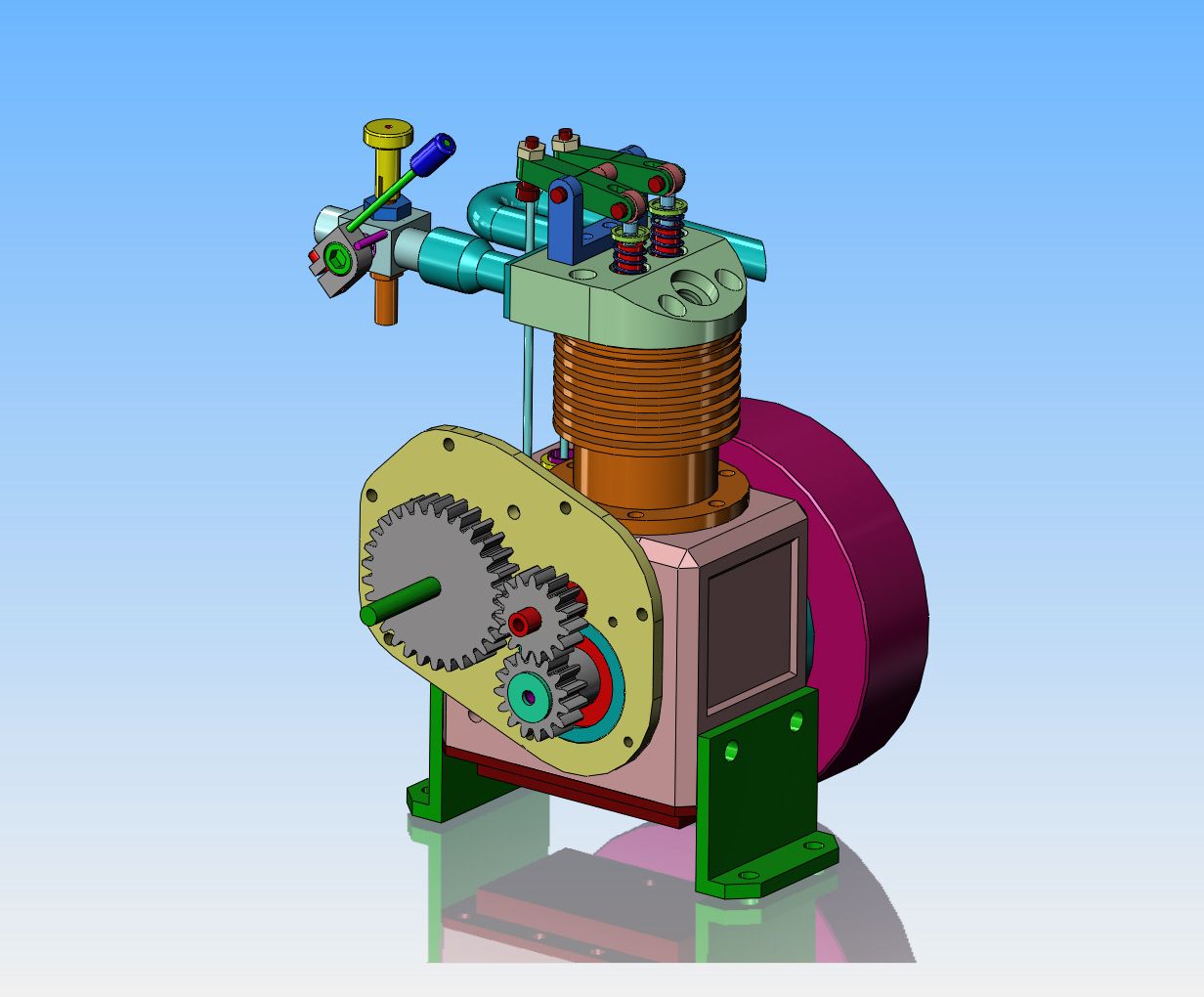
So-----Here we are, 99% finished, complete with Chuck Fellows style carburetor. Since my gear cutters are 24 dp. which cut larger gears than the .08 mod that this engine was originally designed with, the gear cover grew proportionally. I like it. It does have its own very distinct identity now, and as such, will be renamed the "Canadian Cub". I will be starting to make detail drawings sometime this week. I don't think I will post any drawings now, except for the general arrangement, because I have found that there are always changes as I go through the build, and I don't want to have to be constantly revising posted drawings. The drawings will all be done in inch decimal measurements, and the purchased components are a bit of a mish-mash,because the bearings I have used are all metric, while the sparkplug will probably have imperial threads. (Its becoming increasingly more difficult to get inch measurement bearings anyways). So----I assume that since the drawings will only be of use to model engineers in Canada and USA because of the inch measurements, who wants a copy of the finished drawing package once I have worked through the engine build and updated the drawing package to be correct? Let me know now please.



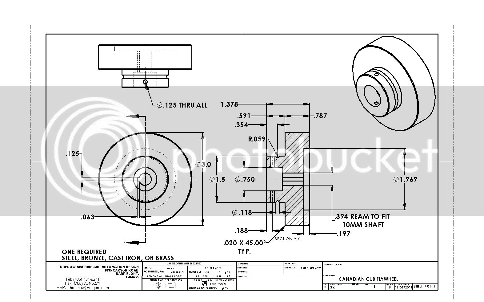
Jeez---I've been detailing my brains out. I'm up to 27 drawings now, and I have a question. I want to build the flywheel in the attached drawing, but the high price of brass is killing me. I do have enough polished 1/4" brass plate which some kind soul off the forum gave me 2 years ago, to cut 3 circles 1/4" thick. I also have enough left over 2" diameter cast iron "butts" to make the smaller diameter. I'm wondering--If I laminate all of the plates and the chunk of cast iron, using a circle of 6 hidden #8 bolts (with the bolt heads counterbored on the side which faces the engine)--would the 3 pieces of polished brass plate blend well enough when turned on the lathe together that the laminations wouldn't be obvious?

Swifty
Well-Known Member
Can you sweat solder the brass plates together and then loctite the cast iron centre in, just a thought.
Paul.
Paul.
Swifty, I don't really know. Its a very large area. I seem to do well soldering and silver soldering small things together, but something 3" in diameter might be a bit beyond my capabilities.
Swifty
Well-Known Member
Years ago, I needed a very thick piece of copper for an EDM electrode, I had pieces that were thinner so I just heated up the pieces individually, painted with flux and let the lead solder flow on the surface of each. Picked up one piece with tongs and placed it inverted on top of the other piece, a little bit more heat, a couple of clamps and it turned out great.
I have great confidence in you ability Brian, I'm sure that you could do it.
Paul.
I have great confidence in you ability Brian, I'm sure that you could do it.
Paul.
Swifty--I'm setting here laughing. There is definitely something a little funny about somebody on the farthest side of the planet having more confidence in my abilities than I do.--I assume you were using soft (plumbers) solder----Right?--Brian
Swifty
Well-Known Member
Yes, that's right Brian, just ordinary plumbers lead solder (or whatever they make it out of these days)
Tin Falcon
Well-Known Member
- Joined
- Jul 9, 2007
- Messages
- 7,207
- Reaction score
- 787
Replied on the other side.
J
REALLY !!! PLEASE if you have something to say about this post say it here .
Tin
This morning I'm up to 37 drawings, and I haven't done the general arrangement yet, but all of the part details are finished. In typical Canadian fashion, this design is 95% imperial "inch" measurements, and about 5% metric. That 5% is because the metric bearings demand metric bores and metric shafts. Some of the things that were done originally in metric just don't convert worth a damn. The nearest "reasonable" imperial dimension is so weird that you can't buy a reamer that size, so I stuck with metric in a couple of places. One of the drawings is a sub assembly of parts found on other drawings, so that means there are 36 "unique" part details. Many of these parts are "two required" so I believe there are something like a total of 99 parts, but that includes 4 bearings, a couple of nuts and bolts, and all of the carburetor parts. Definitely not an engine you would build over a weekend. If I'm not very careful, I may find myself starting to cut metal this week.--Thats okay. We are having a wet cold, totally sucky summer, following a long cold wet sucky spring, following the winter from hell.---I may never go outside again anyways!!!
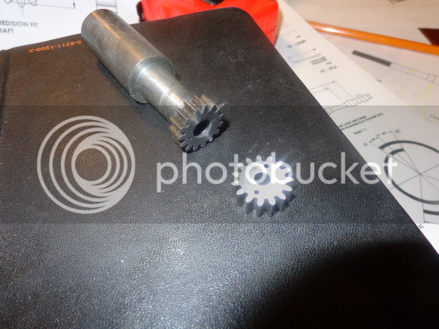
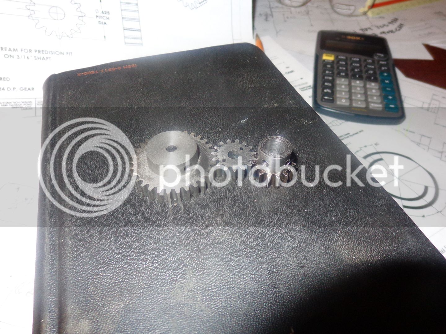
Today we made a small (very small) start. The crankshaft gear and the idler gear are both going to be 15 tooth 24DP gears. They will be 0.25" wide. The steel crankshaft gear will have two set-screws in the hub to hold it in position on the crankshaft end. The idler gear will be made from cast iron---It has no hub and will spin freely on a steel shaft. I chose cast iron for its self lubricating properties--it won't require a bushing. I had a left over piece of cast iron from another job that was 1.5" dia. and 5/16" thick. The o.d. of the gears is 0.708" I used a piece of 3/4" cold rolled steel for the crankshaft gear. I turned it to the correct diameter on the end and in what will become the hub area, then put in a 3/16" reamed bore. I set the cast iron up in my 3 jaw chuck and put a 3/16" reamed bore in it. then I used a short piece of 3/16" cold rolled steel and some Loctite to put the cast iron blank and the cold rolled steel blank together. I then drilled both pieces 1/16" for a couple of pieces of 1/16" cold rolled which will act as "drive keys'. Tomorrow I will set the cold rolled up in my 3 jaw chuck and turn the cast iron down to the same 0.708" diameter as the steel x 1/4" thick. Then I will set it up in my rotary table and cut both gears at once. Then a bit of heat to separate the pieces, and open the bore in the crankshaft gear out to 9/32", which will be the finished bore. The finished bore of the cast iron idler will be 3/16" so no farther changes will be required to it. Then cut off the cold rolled to the desired hub length and drill/tap it for two set screws.
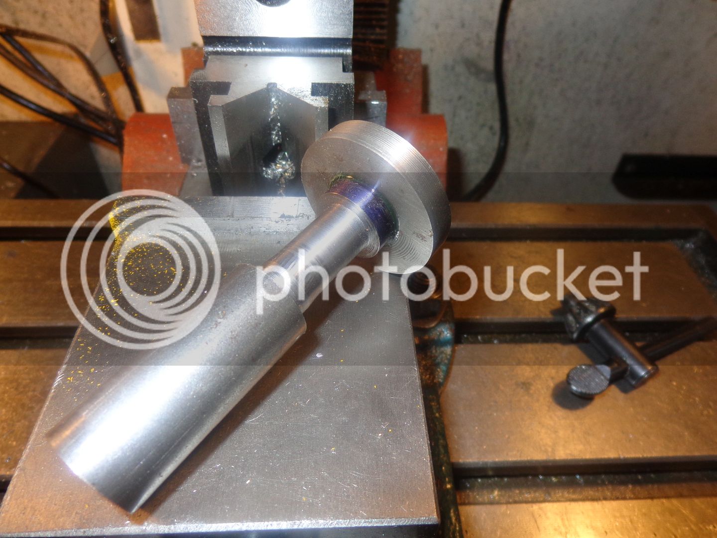


It is absolutely amazing what a large portion of the day gets eaten up by 3 little parts!!!--Don't get me wrong---it didn't take the whole day. Just most of it. The rest of the day was spent building a built in cabinet in my garage for my new generator (The one I bought for the spring flood that never happened) to live in.--If the teeth on that largest gear look a little blunt on the ends, its because they are. I had the gear blank Loctited onto a shaft to turn it to finished o.d., and right on the last "truing up" cut the damn Loctite broke loose. By the time I got it re-Loctited it had gone out of center enough to demand another truing up cut, so its about 0.010" undersize on the outer diameter. That won't effect the mesh, and its hidden inside a gearcase so I'm not too worried about it.

Last edited:
- Joined
- May 27, 2010
- Messages
- 2,999
- Reaction score
- 1,171
Brian,
Congrats to successfully cutting the C.I. Gears w/o half tooth. I did a tally count.th_wav.
Congrats to successfully cutting the C.I. Gears w/o half tooth. I did a tally count.th_wav.
- Joined
- May 27, 2010
- Messages
- 2,999
- Reaction score
- 1,171
Hi Brian.
Plan to build this engine 2015. You got me hooked.
Paul. Are you on?? . My worry is the ''one piece crankshaft.
Similar threads
- Replies
- 0
- Views
- 2K


