Nemett Jaguar--Canadian style

Home Model Engine Machinist Forum

Help Support Home Model Engine Machinist Forum:

This site may earn a commission from merchant affiliate links, including eBay, Amazon, and others.
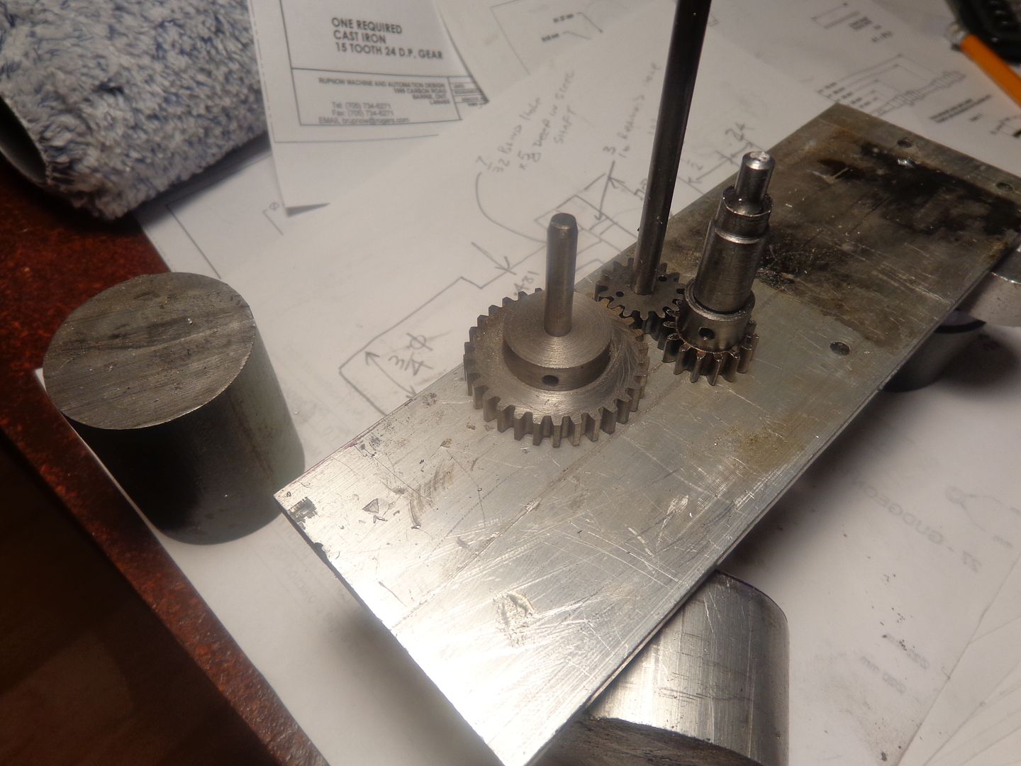
I learned long ago to never trust the centers that my computer or I calculate for meshing spur gears.--(Yes, there was life before computers---I used to do it all with trigonometry.) Now each time I make a gear train, even a simple one with only two gears, I use the measurements that will be used in machining the final part in which the gears will be fitted, to drill and ream holes in a scrap and then mount the gears and see how well they mesh. I must have lived right this week, because they mesh just fine!!! I also discovered a bonus today.(sitting at the left hand side of the picture.) While rooting around in my cast iron short ends looking for something to carve a gear from, I spied one piece that looked a bit larger than all the rest. I don't know what project it is left over from, but it is 1.6" diameter x 2" long. The cylinder for the Canadian Cub is 1.575" maximum diameter at the flange, x 1.705" long. If I can get lucky enough to have this piece clean up and leave me 1.575" at either end, I will have a free cylinder. Dang, I love it when that happens!!!
 
Gus---Where did I say it was going to have a "one piece crankshaft"? I haven't yet decided exactly how I will construct the crankshaft. Granted, it shows up in the model as being one piece, but when it comes to the actual fabrication, it might be one piece, but then again it might be 5 pieces. I have made one piece crankshafts, and found it rather brutal. I have soldered them together from separate pieces. I have Loctited and pinned them together from seperate pieces. I have mig welded them together from pieces. I still don't think I have found the "perfect" way to make a crankshaft. My problem with machining one piece crankshafts is that it is an awful lot of machining, and at the end of the game, if anything is "out" the entire crankshaft and all of those machining hours go into the dumpster.
 
We have a cylinder!!!---Hot off the lathe, literally!!! the bore is reamed to 0.875" but not finished in any other way, yet. I still have to drill a ring of threaded holes at the cylinder head end and a ring of clearance holes at the end where it bolts to the crankcase, but the scary part is done. My parting tool is 1/16", so thats what the grooves and lands are. Gee---does it ever look small!!! I am not going to use a liner, so you can see that a bit of skirt sticks below the flange and about .040" above the top.

 
I decided that I would drill and tap a piece of bar and bolt it to the threaded cylinder end, to allow me something to use as a "witness surface" to ensure that the bolt pattern in the far end of the cylinder would get drilled in the correct angular orientation. Then I decided "Well darn---If I have to drill five holes in a piece of bar, why not just make the cylinder head?" I was doing fine until I drilled and counterbored the second last hole. As soon as I was finished drilling it and stepped back from the machine, I thought,---"Damn, that looks like its a long ways back from the left end of the bar----". Sure enough--instead of the .494" ordinate dimension on the drawing, I had for some reason picked up on the .748 R just to the right of it about an inch. CALMLY---I reset the dials and redone the second last hole---and by Golly, I think I may get away with it. I think that with a little creative blending in that area, when the .748" radius is cut on the cylinder head the "bad hole" is going to go away!!! On a positive note, all of the bolt holes I had drilled in the bar using ordinate dimensions lined up perfectly with the threaded holes in the cylinder. I don't have readouts on my machines, so everything is set up using the dials for X and Y positioning. I am not a big believer in "marking through" with transfer punches. I have found I have trouble every time I do that.
 
I spent a great portion of the morning figuring out the cams for this thing. (actually, the same cams used in the original Jaguar design) I want it to turn the opposite way to the original Jaguar engine, because I use my variable speed electric drill as a starter, and when the engine must be turned counterclockwise to start, the chuck "unloosens" itself from my "starter spud". I'm not sure why I found this so difficult, but it has a lot to do with the fact that I have built so many hit and miss engines with only one cam that two cams confused the daylights out of me. At any rate, I got it sussed out, but it was a struggle. The engine will turn clockwise when viewed from the flywheel end. Since there are 3 gears in the timing gear train, the camshaft revolves the same direction as the crankshaft. The intake valve begins to open 15 degrees before top dead center and closes 45 degrees after bottom dead center---a total of 240 degrees of "cam influence" on the tappet. The exhaust cam has the same profile as the intake, and begins to open 40 degrees before bottom dead center and closes 20 degrees after top dead center, again a total of 240 degrees of "cam influence".
 
Last edited:
My God!!! I feel like I have just excavated a hole big enough to hold a Toyota, and deep enough to come out somewhere in the Queensland!!! This is one of those times I envy you guys with the cnc equipment.--Brian
 
I am really surprised at how small this is turning out to be. For having such a large (7/8") bore, it is half the size of a comparable hit and miss engine.
 
Okay---About the crankshaft.--As you can see, its a hefty little rascal--and its only 3" long!!! I have been wanting to try some of the "stress proof" steel that seems to be so popular for making crankshafts out of. Yesterday I got a real 'buy' on a 12" end at my metal suppliers, so I will be making a one piece crankshaft.---The first crankshaft anyways----
 
Okay---About the crankshaft.--As you can see, its a hefty little rascal--and its only 3" long!!! I have been wanting to try some of the "stress proof" steel that seems to be so popular for making crankshafts out of. Yesterday I got a real 'buy' on a 12" end at my metal suppliers, so I will be making a one piece crankshaft.---The first crankshaft anyways----


Hi Brian,
Please post when cutting the crankshaft. Gus has yet to cut such one piece crankshaft.Will monkey see, monkey do.
I am about to make an excavation to reach Paul in Dandenong,Victoria,Australia.
 
Gus, if you do the bore first in the lathe, this removes a lot of material, see my build.

By the way, if you end up in Dandenong with your excavation, you will miss me, I live in Mount Martha.:)

Paul.
 
Last edited:
Today I bored out the hole for the register on the bottom of the cylinder to fit into (my 1" reamer was too long--my mill didn't have enough headroom to let me use it.) and drilled and tapped the 6 holes to match the bolt pattern on the flange of the cylinder. My God----What filthy little piggies those bolts are when trying to fit them into place. I went down street and bought a set of ball end hex wrenches because it was the only way I could get at them to tighten them.
An almost direct cross reference for M3 bolts is the #5-40, which is a bastard thread size, but I use it a lot because it is the thread you can put on a 1/8" rod with no modification to the rod diameter. After bragging yesterday about how well my bolts lined up when I drilled the bolt pattern using the dials on my mill, Hubris bit me on the arse today. Five of the bolts went in just the way they were supposed to. One of the bolt holes wandered off just enough that I had that cylinder on and off 3 times, "stretching" a bolt hole. That cylinder is cast, and you can't crank down on any one bolt to draw things into place or the flange will crack. I also tapped the crankcase for the capscrews that hold the support feet on, and made up the support feet from some 1/8" thick aluminum angle.
 
I had to break down today and buy an "Old mans work-stool". My arthritis has been so exceptionally bad from the cold wet spring we are enduring that my legs and lower back have been killing me when standing at the mill and lathe. I'm not sure if this is going to work for me or not. It feels weird, setting down to run the lathe or mill. Oh well, I only paid $10 for it from the "buy and sell" adds in the local paper, so if I find I can't use it, I'm not out a fortune.
 
Hi Paul, Hi Brian.

I am so envious of you guys with big lathes,mills and big machineshop and could take bigger cuts.When you live in flat and the balcony is your workshop,putting in bigger machine tools is not an option.So I have to live with the mini lathe and mill and take mini bites into the bar stock to cut Nemett Engines.:rant:
Making good progress on the crankcase. The bearing housing will snug fit in. Will bore the other end followed with the excavation to Mount Martha and Paul Swifty. Gus watching both Brian's and Paul's thread. Still very much a beginner and prone to goofs reading dimensions/details and slip on the last cuts.:hDe: My darling wife thinks I am crazy at making engines and not making $$$$.;)
 
Gus--I've heard it said that "Size isn't everything!!"---But I don't think that applies to shop machinery. As far as making goofs reading dimensions--I do it myself, even when reading my own drawings. I would hate to have had to make my living working as a machinist.---but I love doing it as a hobby. The world doesn't always have to make sense.-------Brian
 
Gus, you do amazing work with small machines on your balcony, having larger machines can be a problem with smaller parts sometimes.

Paul.
 
This is my mornings offerings to the Machine Gods.---Sure doesn't look like much!!! The big disc (big being a relative term) is the holder for one end of the crankshaft bearing, which is shown setting on top of it. I like to make the bore about .001 to .002" larger than the actual bearing outer diameter. This way, when I get everything final machined, I can put a bit of Loctite around both bearings and install a straight alignment bar just before I seal up the case and tighten all of the bolts down. If there is any minor machining misalignment the bearing can shift around a little bit until it is perfectly aligned with no bind. When left overnight, the Loctite takes on a permanent set, and there is no bind on the shaft and/or bearings. The small disc with the shallow counterbore fits into the hole in the side of the crankcase behind the small camshaft bearing and serves to plug the hole and to give a definite end position to the camshaft. The 10mm crankshaft bearings were reclaimed from a machine of some kind?? that I dismantled, and the camshaft bearings were originally used on my first build of the Atkinson engine.
 
Brian, if you check out my Nemett build, you will see my solution to make getting the screws in and tightened much easier.

Paul.
 
Paul--I can get at my screws---just not easily. The ball end hex wrenches help a great deal. I will not have that cylinder on and off enough times to justify modifying the cylinder.----I hope---The secret is to put all the bolts in place before setting the cylinder onto the crankcase.
 
Last edited:

Latest posts

Back
Top