MB building Upshur Farm Engines.

Home Model Engine Machinist Forum

Help Support Home Model Engine Machinist Forum:

This site may earn a commission from merchant affiliate links, including eBay, Amazon, and others.
Rick--I may be an Ace design engineer, but that doesn't mean I know anymore about carburetors than the next guy. However---I havn't had time to do any real difinitive testing on the Upshur carb, and yes you are right, there is a .015 intrusion into the main air gallery by the two 1/8" diameter peices. Whether this creates much venturi effect or not is something that I will do more testing on. However, all is not lost. If the parts do not extend a full .015 into the air stream on the carb I built, there is enough room to drill 2 more 1/8" holes at 90 degrees to the existing ones and make up a couple of "intrusion plugs" and loctite them into place, creating the elusive Venturi effect.
UPSHURCARB.jpg
 
164) For today's post I made the 'spool' for the hit-n-miss mechanism. I was rather busy today with home related projects that limited my shop time. After drilling and reaming the bore, the profile was cut with my parting tool. I used six carriage moves to make the cuts, plus a final parting cut.

P1040608.jpg


165) The machining on the first one was not quite up to my expectations. I had forgotten to touch up the cutting edge after using it to cut off the previously made valve stem assemblies. And I found the final 'cut off' to be short by .002" leaving the last disc only .060" wide. After honing the cutting edge and adding .002" to the final figure, I machined the 5 spools needed with out any further problems.

P1040613.jpg


I didn't get much done today, but the spools turned out well.

-MB
 
166) Good news Guys! George's friend dropped of my first batch of flywheel casting today. They look really good, and I can't wait to machine them up. For now though, they will have to wait. Thanks again George, your pattern work was superb and exactly what I wanted! :bow: :bow: :bow: :bow: :bow:

P1040624.jpg


-MB


Good Morning Rick---Happy christmas day!!!! I notice that on both my Kerzel engine and on the Upshur plans I have, there is no provision for oiling the wrist pin. On the webster I built, he does have a very neat trick whereby a small tube runs from the outside of the piston skirt thru to the wrist pin, and there is an oiler at the end of the cylinder which not only keeps the piston/cylinder wall oiled, but also delivers a drop of oil down the tube to the wrist pin bearings every time the piston gets to the end where the oiler is. Have you thought about that? I just built a huge set of main bearing oilers for my engine, (see Drip oilers---with a secret) and I MIGHT build a cylinder oiler for the cylinder so I can avoid running mixed fuel. I'd like to have this engine set up to run for hours at a time (if I ever get it running correctly). and the lack of oil to the wrist pin concerns me. I have just checked both sets of plans, and unfortunately the wrist pin area on both engines doesn't get far enough away from the cylinder head to be directly under a drip oiler at the far end of the cylinder, unless the tube was set into the piston at an angle.----Brian
 
Brian Rupnow said:
Good Morning Rick---Happy christmas day!!!! I notice that on both my Kerzel engine and on the Upshur plans I have, there is no provision for oiling the wrist pin. On the webster I built, he does have a very neat trick whereby a small tube runs from the outside of the piston skirt thru to the wrist pin, and there is an oiler at the end of the cylinder which not only keeps the piston/cylinder wall oiled, but also delivers a drop of oil down the tube to the wrist pin bearings every time the piston gets to the end where the oiler is. Have you thought about that? I just built a huge set of main bearing oilers for my engine, (see Drip oilers---with a secret) and I MIGHT build a cylinder oiler for the cylinder so I can avoid running mixed fuel. I'd like to have this engine set up to run for hours at a time (if I ever get it running correctly). and the lack of oil to the wrist pin concerns me.----Brian

I saw the provision for 'oiling the wrist pin' on the Webster a few months ago when I downloaded the plans. Personally I won't bother with adding it if I ever build one . Why not? Before running my engine's I always put oil on all of the moving/bearing surfaces with a 'needle oiler'. Areas that need oiling are the valve stem guides, rocker arm pivot, rocker arm clevis, push rod guide, gears, gear pivot pin, cam, crank bearings, piston rod journal, governor assembly, etc. With all these oiling points, adding oil to the wrist pin is just part of what I do to before running any engine. After the initial thrill is gone I never demonstration run an engine for more than a few minutes.

Scale models use functional oilers, and rightfully so. At shows they can be run for long periods of time. If I add any oilers to my builds I won't rely on them, they will be used for cosmetic reasons only. If I don't add oil to my fuel than I will defiantly need a cylinder oiler. The fuel will have a tendency to 'wash' the bore of manually added oil, and adding it with a needle oiler while the engine is running is not practical.

-MB
 
EDIT

Brian see reply re wrist pin lubrication in your oiler thread

Sorry MB,Jason
 
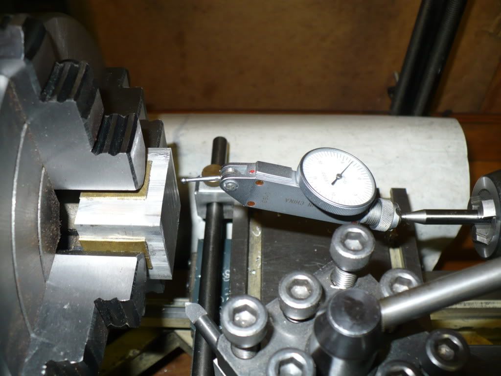
167) With the holiday winding down I took the opportunity to post some pictures and clear my camera.
To make the 'carrier" for the governor a block of aluminum was centered and squared up in the lathe.

P1040627.jpg


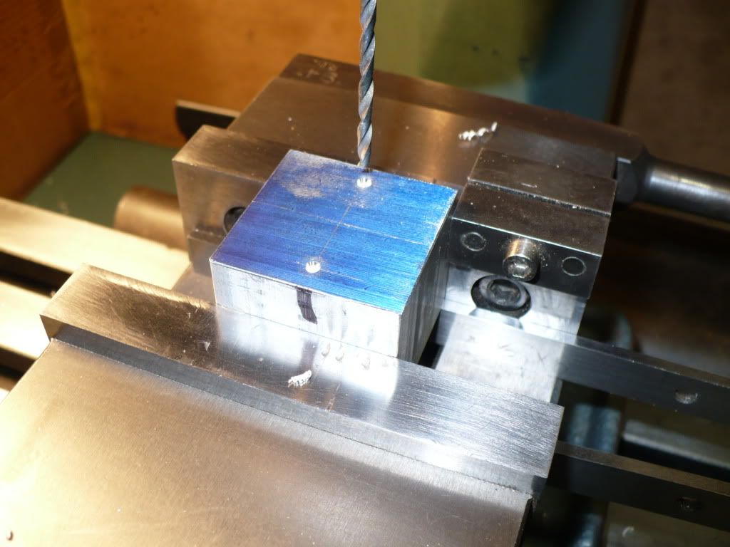
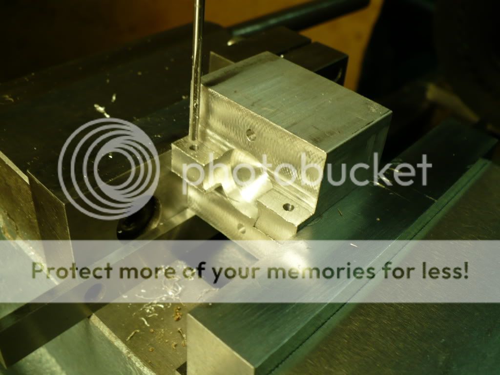
168) I drilled two clearance holes for the bolts that will hold the carrier to the flywheel.

P1040631.jpg


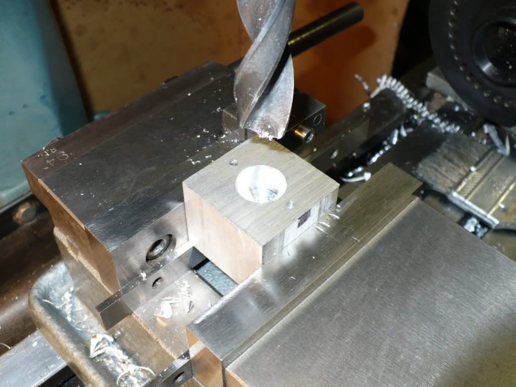
169) The center hole was drilled in stages of progressively larger drills to keep the size under control. They came out about .003 oversize which will not present any problem. The hub they go over with be dimensioned to suit.

P1040635.jpg


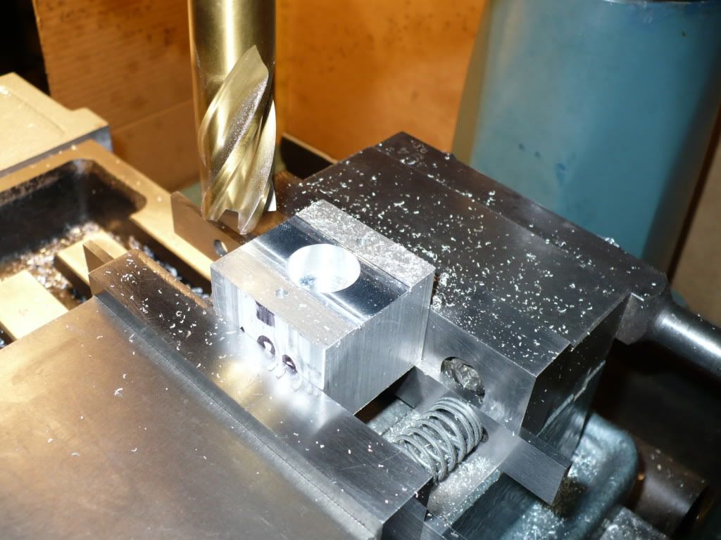
170) I took one central pass over all the work pieces to true them up to the same height. This will make the set up for subsequent machining steps easier.

P1040639.jpg


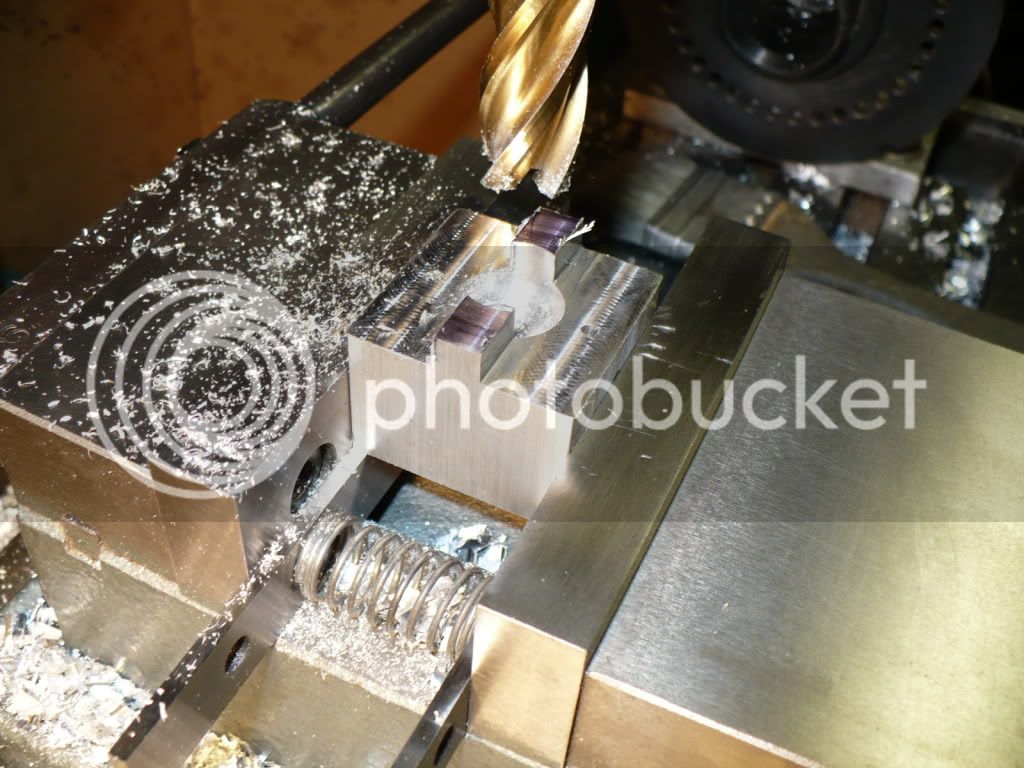
171) Milling the profile using two cuts.

P1040643.jpg


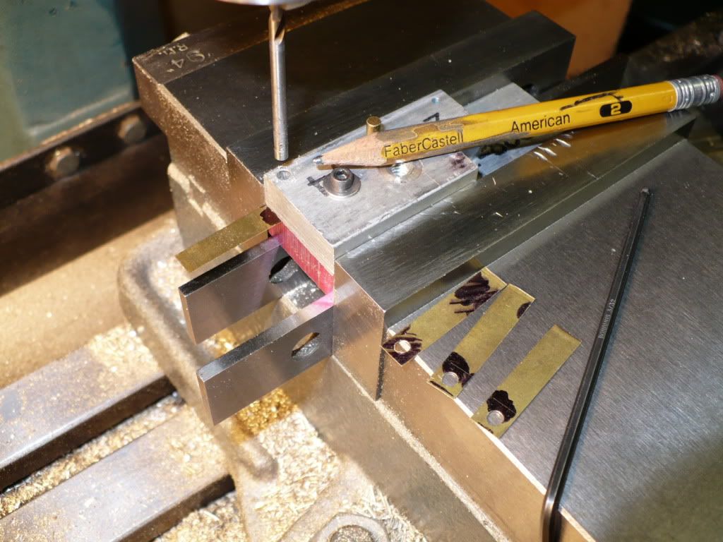
172) At this stage I drilled and reamed the two holes for the 'arm' pivot pins.

P1040651.jpg


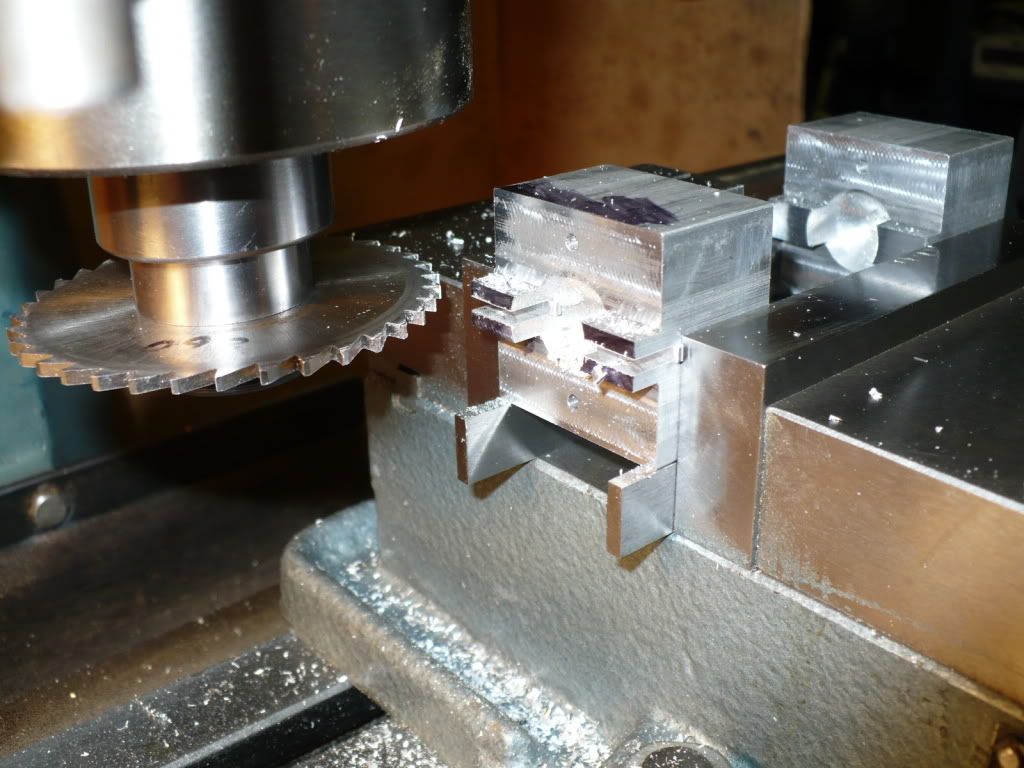
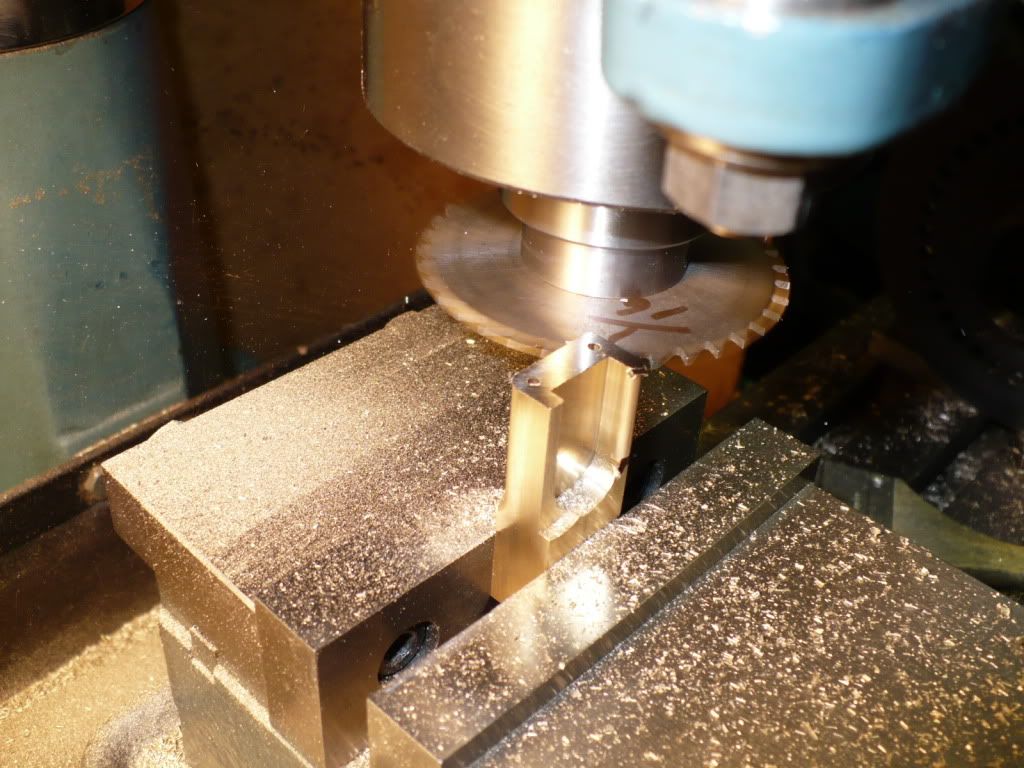
173) I cut the slot with a slitting saw with one slow pass. I used square stock to make the different operations a simple indexing. Much easier for me than starting with 1-1/2" round stock with the equipment that I have.

P1040652.jpg


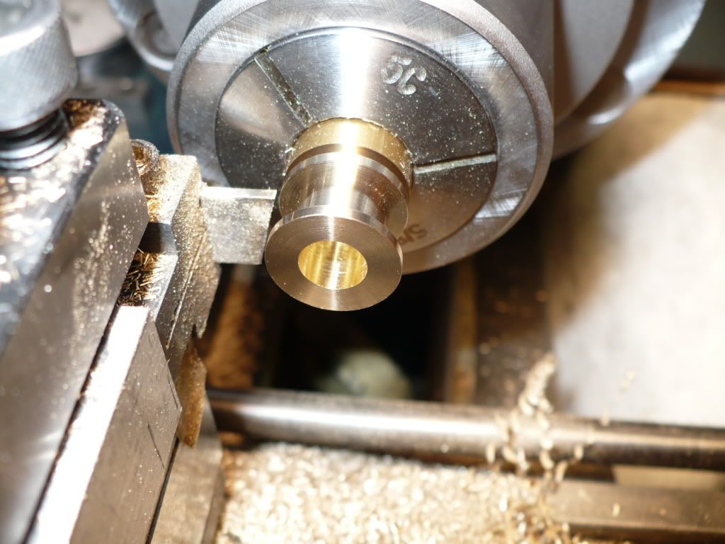
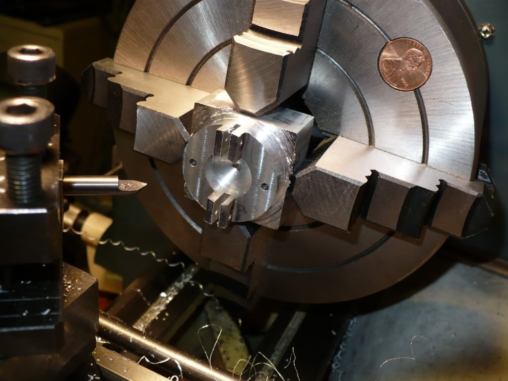
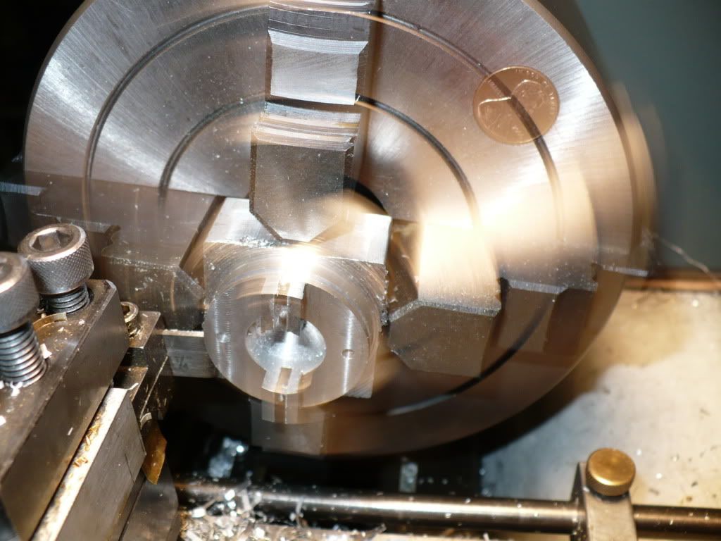
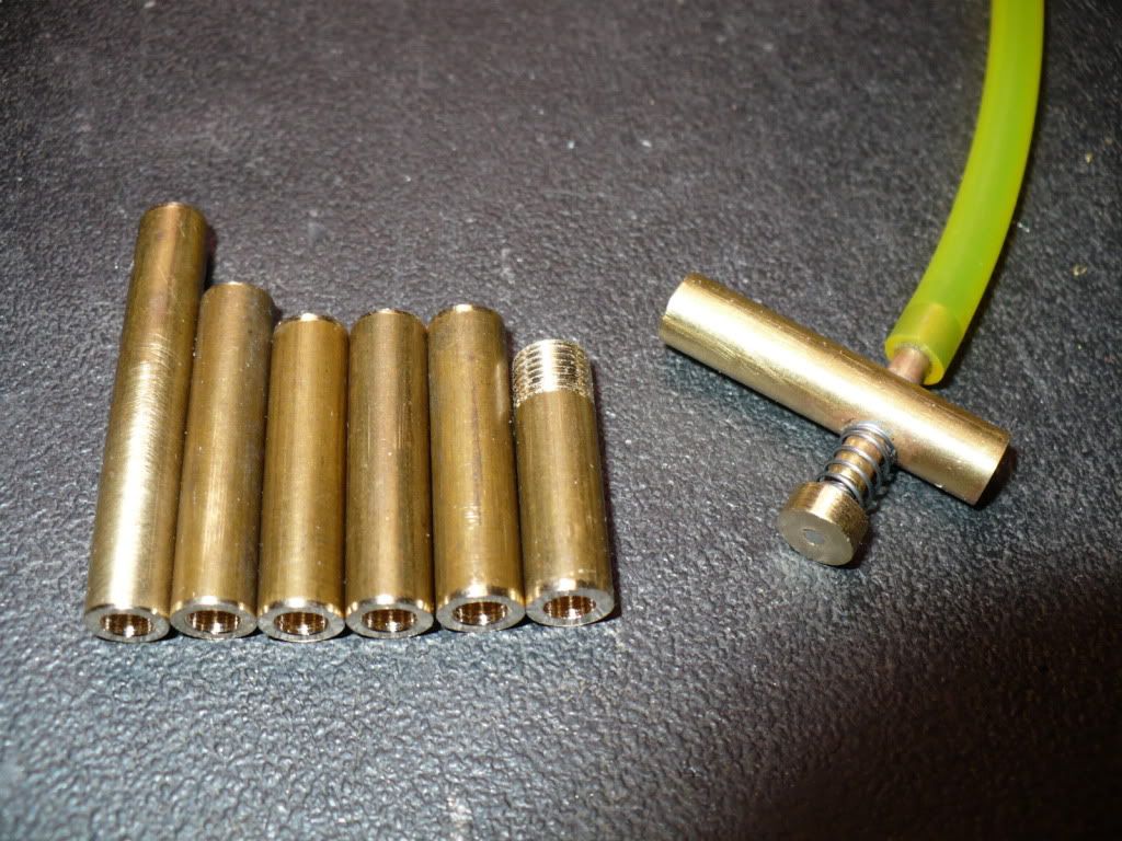
174) Back to the lathe to create the reduced 1.406" round profile.

P1040659.jpg


175) This was the nerve racking part. Using a parting tool on this large of a diameter was difficult with my 9 x 20 lathe. The tool post on these is somewhat less than rigid. Even though I used the lowest speed it was still touch and go. I always thought it was my lack of ability, but it turns out that others have also had this ridgidity problem. Time for me to upgrade this area and be done with this problem for good.

P1040669.jpg


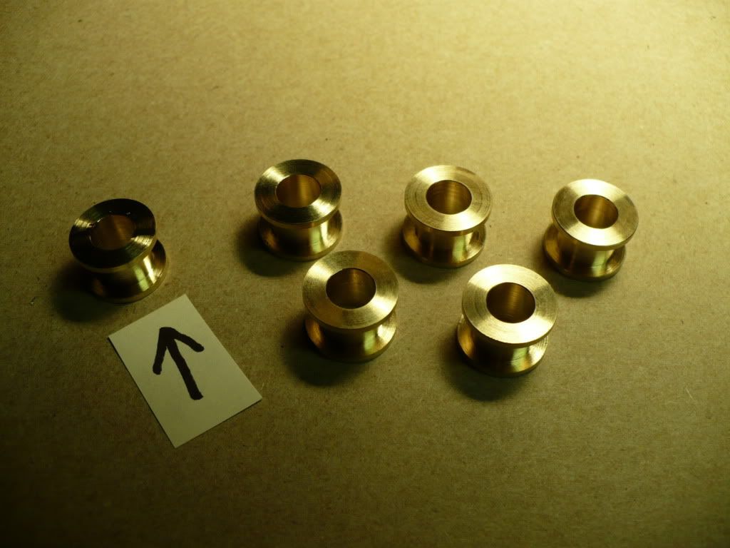
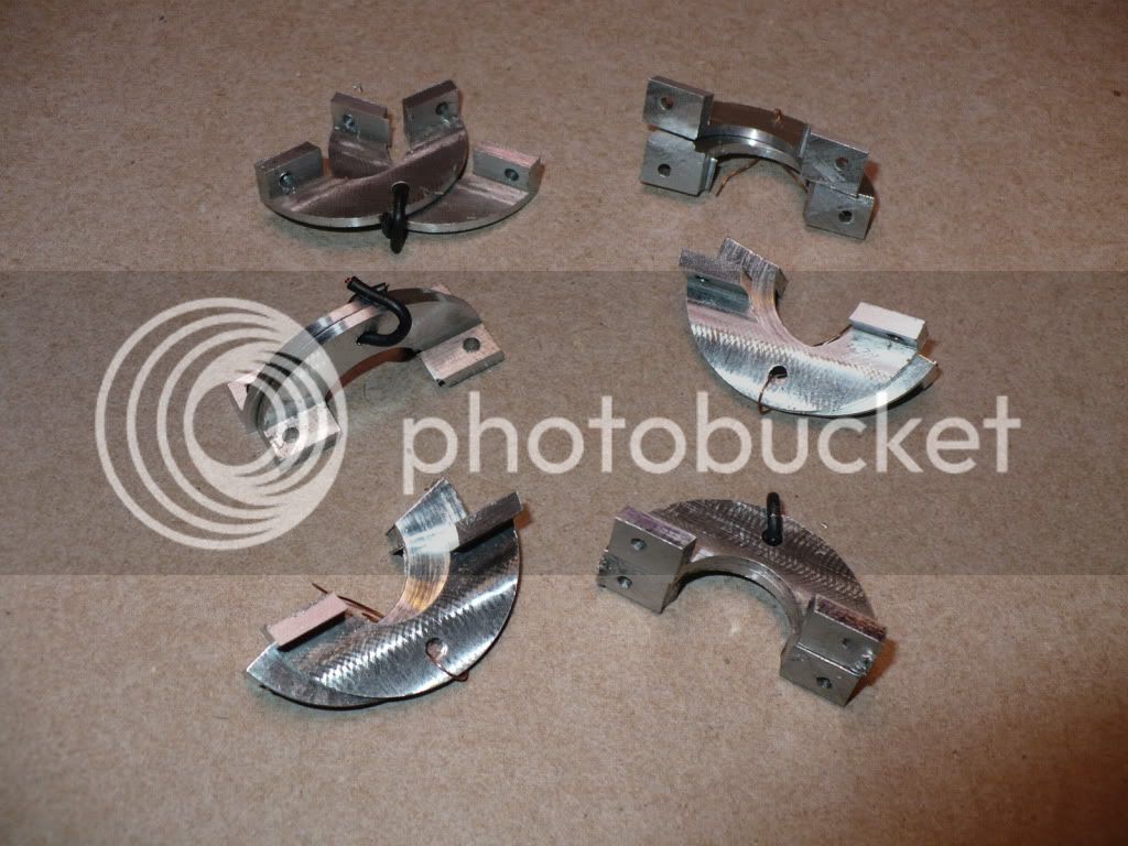
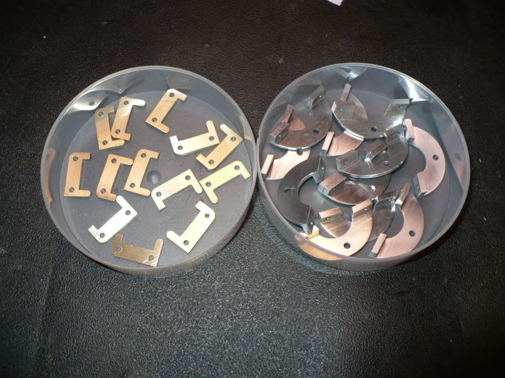
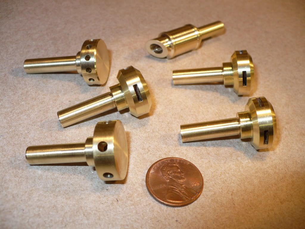
176) I made an extra set just in case of a miss-hap.

P1040670.jpg


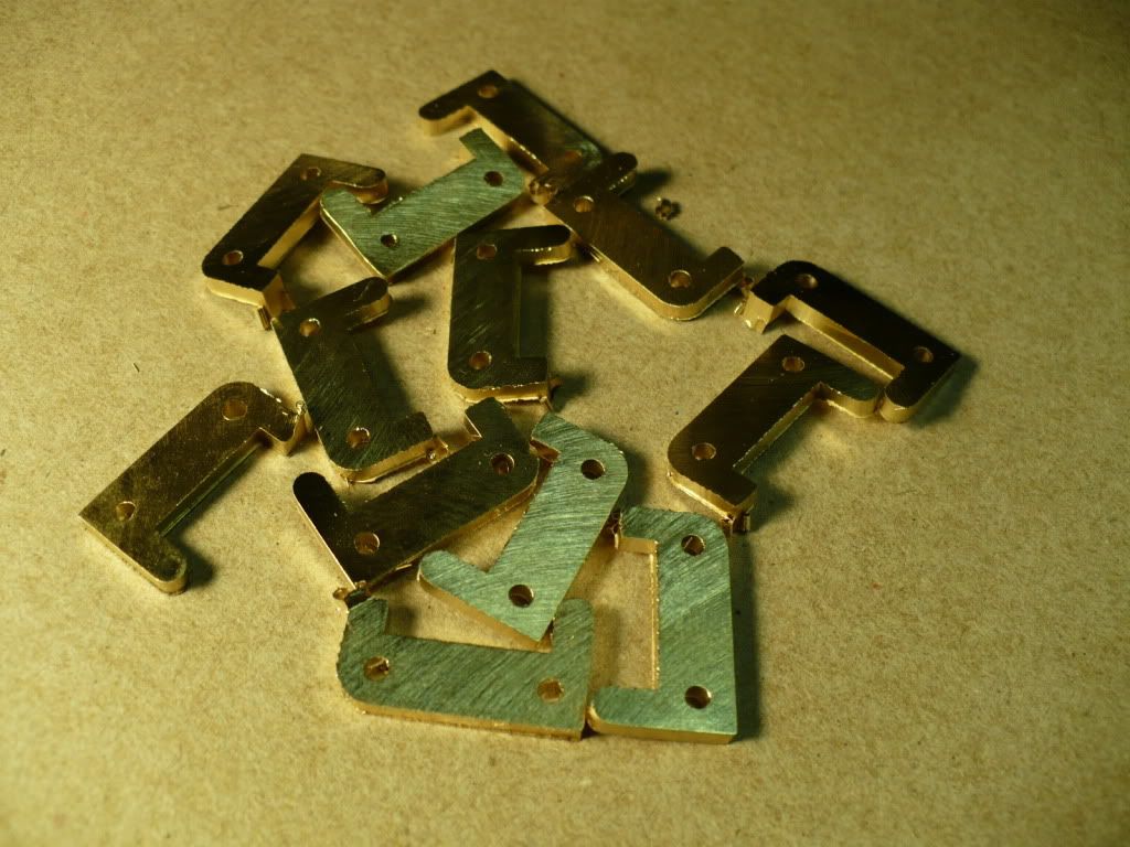
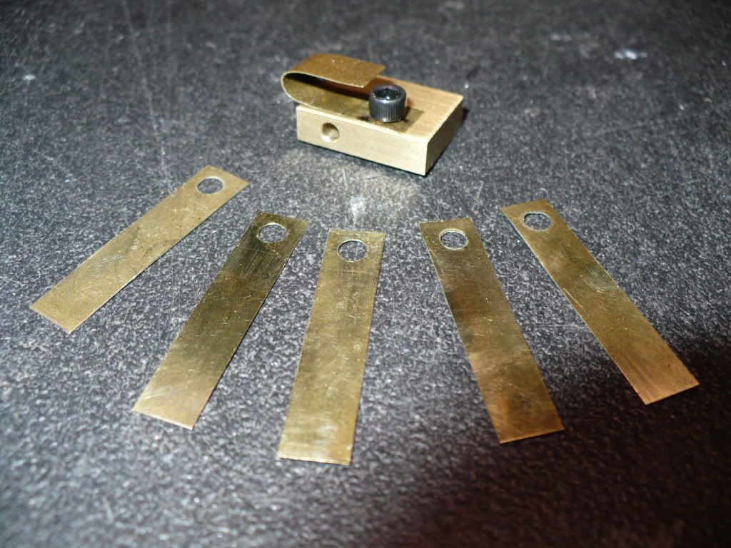
177) Instead of the 2-56 screws used as pivot points, I will be using 3/32" pins held in place with E-clips. To accommodate the 'clips' the two pivot holes on the 'carrier' had to be shifted .010". This meant that the previously made 'arms' had to be made over with a matching hole location. This time around I added profiling that's shown a little vaguely on the plans. I originally intended to add this step later, during a trial fit up.

P1040673.jpg


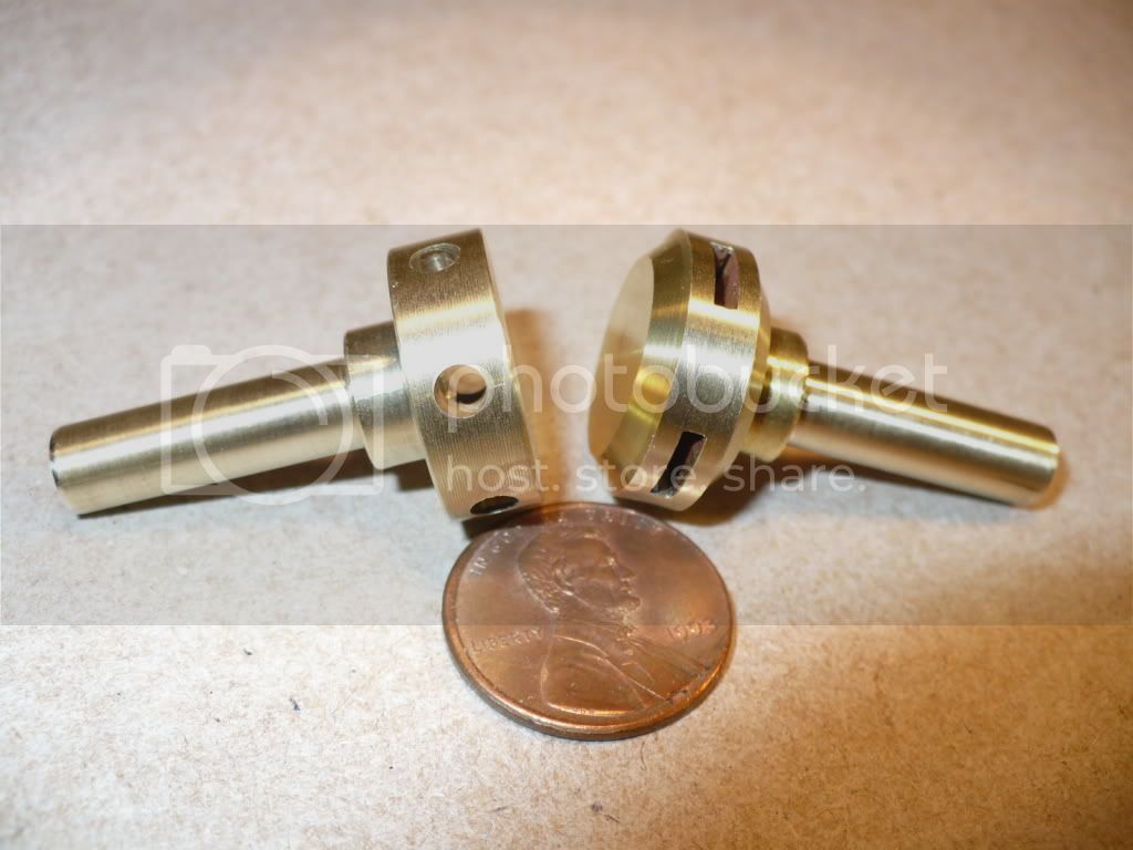
178) Theirs going to be a lot of intense filling and sanding to get these tiny parts up to standard.

P1040682.jpg


Over the next few days I'll finish up these parts, spend some time cleaning up the mess, and organize the shop a bit before I tackle the next part(s).

-MB

 
Things are looking good, Rick. I like the idea of making the round carrier shapes starting with square stock. Saved a fair bit of extra setup time. I sometimes forget that when making round things.
You mentioned cleaning up shop. I generally get the impression from reading your threads over our many months here that you keep pretty tidy machines. Except for the swarf you're making at the time, they look well cared for and clean. Kind of nice to see that. Thm:

Something about wrist pin oiling; They do get oiled if you have a cylinder oiler on the engine. Since the pin is below the rings, the wrist pin hole in the piston picks up oil as it sweeps the side of the cylinder. The pin and rod have such a small rotation that it doesn't take much. Your drop or two of oil with the needle oiler would probably last quite some time, anyway.

Dean
 
That was an interesting post MB (as most of them are).
How did you come up with the procedure? Was it yours?
I'm sure I would have had all kinds of problems trying to make such parts.
 
Deanofid said:
Things are looking good, Rick. I like the idea of making the round carrier shapes starting with square stock. Saved a fair bit of extra setup time. I sometimes forget that when making round things.
You mentioned cleaning up shop. I generally get the impression from reading your threads over our many months here that you keep pretty tidy machines. Except for the swarf you're making at the time, they look well cared for and clean. Kind of nice to see that. Thm:

Something about wrist pin oiling; They do get oiled if you have a cylinder oiler on the engine. Since the pin is below the rings, the wrist pin hole in the piston picks up oil as it sweeps the side of the cylinder. The pin and rod have such a small rotation that it doesn't take much. Your drop or two of oil with the needle oiler would probably last quite some time, anyway.

Dean

Hi Dean. If I make a good amount of chips, a daily clean up helps me to keep my footing. I don't like the unsure feeling of walking on freshly laid gravel. I try to clean up at the end of the day if I have enough time or strength left in me. If I'm making small parts, I can get usually away away with just taking a few minutes to vacuum the machine. I'm not real fussy about cleanliness, although starting out the day in a clean shop is nice. Thank you for your kind words

Starting out with a square block of aluminum was easier to set up, and the only logical choice for me. I have a foot of expensive ($50) 1-1/2" brass round stock, but just couldn't see the sense of using it on this part. The more logical choice of scrap yard aluminum square bar weighed in at under 3-lb, and cost me less than $3.

Since I always oil my engines before a run the wrist pins are not an issue, and they hold on to oil very well. The only engine that ever concerned me is the radial shown on my avatar. With its enclosed crank case oiling individual points is impossible. To eliminate any lubrication concerns I fill the crank case up 1/3 with 10-wt oil. The oil splashes all around the interior and lubricates everything including the wrist pins. I know that for a fact, because I unscrewed the oil cap while running the engine, and oil sprayed out all over me! I added a drain plug on the bottom of the crank case so that oil changes are possible.

A little silly, buy possible! ;D

-MB
 
zeeprogrammer said:
That was an interesting post MB (as most of them are).
How did you come up with the procedure? Was it yours?
I'm sure I would have had all kinds of problems trying to make such parts.

Hi Zee. I'm glad you found my post interesting. Its getting harder, and harder, to please the crowd these days. :shrug:

I just worked out the procedures in my mind by meditating in the porcelain library. I don't recall ever seeing any one making a carrier, so yes, it's all mine. Although I doubt if I'm the only one that's ever made a round piece using a square to start with.

Quoting Zee; "I'm sure I would have had all kinds of problems trying to make such parts."

I don't think you would have any problem making the 'carrier', if that's the part your referring to. Look the pictures over again, its just one simple step after another.

I know you could do it! Thinking about it, is sometimes more work than doing it. :idea:

-MB
 
Hey MB,

I usually check in on your build ever day. I get a little careless about leaving comments, but do enjoy your work. I continue to learn from you. Building 6 engines at one time is beyond my comprehension! ;D I think I have adult ADD.

Chuck
 
Hi Chuck. Thanks for stopping by to take a look, your comments are always welcome. I realize that we all have projects that were working on, and they limit the time we can spend trying to keep up with all the new posts. I learn a lot from you, and that's why without this forum I would be lost, and with out any direction. I took on a bigger project than I realized, and I don't see when it will end. I find myself spending a lot of time doing research on simple items like the 'fuel line' for example. Looking at all the different materials and sizes, ones to small, ones to big, you know what I mean. A lot of the members already crossed these bridges and don't need to waste time on these basics.

I try to stay busy enough so that I don't have the time to think about my physical and mental shortcomings. This is where a slightly overwhelming project has its benefit. :D

-MB
 
I'm at a stand still today, and pulling whats left of my hair out. I'm trying to figure out how to make the 'arm return spring'. It attaches to the 'push rod guide' with a single screw. There are no dimensions given on the drawing of it. Its a flat 'J' shaped piece of thin metal. The only information provided is, "M/F thin sheet metal (1)".

Any idea what that means, I'm lost, and getting a head ache! :wall:

-MB
 
#179 I finished up filing and sanding the brass 'arms' and the aluminum 'carriers' over the last few days. With the multitude of surfaces to deal with, these took quite a bit of time.

P1040686.jpg


#180 I started on the 'arm return springs' by shearing off strips of shim stock and cutting them to length. To punch the bolt clearance holes, I made a quick two piece fixture held together with a single cap screw plus a line up pin. After drilling through both the drill bit was reversed on the chuck and used like a punch in a punch press. This is a dubious method that can damage a drill and/or chuck, so use your discretion about using this method.

P1040690.jpg


#181 Shown below are the semi finished 'arm return springs'. I put one that was bent to shape in position on a push rod guide. The 'arm' will be centered on the push rod hole seen in the picture. I had no idea on how to make these with out any given dimensions on the plan, so I went ahead and winged it by measuring the drawing. I used a springy brass shim stock since I didn't have the specified "M/F thin sheet metal," what ever that is.

P1040694.jpg


#182 My Tygon fuel line finally arrived today, took a little longer than I expected, but at least its the right stuff. I started on the exhaust tubes today, and after cutting one (the long one) to length and drilling it through I realized that they look way too simplistic. I cut the rest of them with three shorter lengths. I'm going to experiment with different muffler shapes and sizes threaded on the pipes to see what I can come up with. I would like them all to be at least slightly different. The plans call for a piece of tubing from a hobby shop. I prefer to drill my own to have something a little more sturdy with threaded on mufflers.

P1040707.jpg


#183 My broach set also came in today! I just couldn't resist showing off what I consider to be an extravagance. Not my doing alone, "Honey" talked me into buying the more expensive duMont made in USA set. I just ordered it the other day, now that what I call great service!

P1040702.jpg


#184 The quality looks super, inside and out.

P1040703.jpg


I need to deal with my lathes tool post's lack of rigidity, buy some key stock, make a tap extension, and muster up the courage to machine the flywheels. But first I need to deal with a lot of small parts, and get to the main frame work for the engines. There's still a lot of work ahead.

-MB


Hi Rick,
I'm glad to see you are buying some very nice tooling. I won't have to travel far to use them. :big: :big:
George
 
gbritnell said:
Hi Rick,
I'm glad to see you are buying some very nice tooling. I won't have to travel far to use them. :big: :big:
George

Hi George. "use them"? I bought these just to 'look' at!

I promise to let you 'look' at them when you stop by. Rof} Rof}

-MB
 
Any idea what that means, I'm lost, and getting a head ache! wall bash

-MB

'Made from' thin sheet metal?????? Just a wild guess.

You're doing really well MB, I'm struggling enough doing a single engine.
 
tel said:
'Made from' thin sheet metal?????? Just a wild guess.

You're doing really well MB, I'm struggling enough doing a single engine.

Hi Tell. Thank you for the compliment. I prefer smaller projects like I did last year that only took two weeks to complete. I've been struggling along with this project for over 2 months now. Every every time I look at the plans I find more and more parts to make, and more problems to solve! :redface2:

Oh, how I long for a wobbler. :'(

-MB
 
#185 To start off the new year I made some 'new' parts. The plans call for the exhaust to be a strait piece of tubing. A little to plain for my taste, so I went ahead and made a few variations that can be changed out or switched around easily. These are very simple parts to machine so I didn't take any boring set up pictures. The only trick part that I can think of is drilling the four rectangular holes in three of them. :D

P1040733.jpg


#186 Did I get you to start thinking, " this guy is nuts, you can't drill a square hole." Ah! But you can fake it by making the muffler out of two pieces, and milling two cross slots with an end mill on the lower half that's threaded onto the pipe. The upper 'cap' is then soldered on, and a light truing cut on the O.D. in the lathe, helps to conceal the joint line.


P1040734.jpg


How I long for a wobbler
Oh to cobble
To make it wobble
Will it run
It will be fun
Love a wobbler

-MB
 
Back
Top