MB building Upshur Farm Engines.

Home Model Engine Machinist Forum

Help Support Home Model Engine Machinist Forum:

This site may earn a commission from merchant affiliate links, including eBay, Amazon, and others.
narrowgauger said:
MB,

very informative & enjoyable thread. Great information, particularly the use of fixtures. I certainly now look forward to seeing these engine operational.

Have a question for you; in picture 81 you are using a spiral cutter, which seems like a jewellers bir with a spiral cutting face. Could you please tell me what the proper name for this cutter is and your supplier source.

thank you for the input in advance

Bernard

The Model Works Australia

Thanks for the compliment Bernard. The cutter you refer to is a 'single cut' h.s.s. burr. The burr's are commonly available in single cut, and double cut. They come in different sizes and shapes. Below is a link to just one of many suppliers. If you click on one of the boxes above the pictures it will show the available sizes in that particular style. They should be available from most all machine shop suppliers.

http://toolinghouse.com/hssburrs.aspx

Here's the one I have.
http://www.silver-seal.com/product/...e&utm_medium=CPC&utm_content=&utm_campaign=78

-MB
 

132) As I mentioned in a previous post, I didn't care for the idea of the rocker, clevis, lever, and governor arm pivoting on the threads of 2-56 screws. So I went ahead with my idea of using 3/32" steel pivot pins retained with E-clips.

Using a 3/32" collet on the lathe and measuring with a rule, I cut off the drill rod slightly longer than the finished length. The pins were then sized to length using a cordless drill and belt sander, while checking with a dial caliper to get them all within a close tolerance. This was important since the groove locations will be based on zeroing out the groove cutter from the ends of the pivot pin.

P1040448.jpg


133) In the picture below a batch of pins is already sanded to length. I needed three different length pins for the various pivot points on the engine. The next step is cutting the groves for the E-clips.

P1040451.jpg


134) I used a paper shim to locate the edge of the pin with the edge of the grooving tool. This not only made the locating easier, it also gave me a little clearance so that the clips would slip in without any side interference. I cut the pins 1/8" longer than the width of the parts they went through, this gave me 1/16" of the pins protruding on each side.

P1040439.jpg


135) After zeroing out my dial indicator the carriage was shifted .062" to cut the grooves .010 deep. The pins were then reversed in the collet to cut the grooves on the opposite ends.

P1040432.jpg


136) After the grooves were cut the precision pins no-longer fit into their reamed holes. I chucked each pin into my cordless drill and used a round jewelers file to remove the burr, and finished up with fine sand paper until each pin would fit into the reamed holes with out any binding.

P1040453.jpg


137) I used a solid block of brass with a reamed hole as a gauge to check the pins. If I felt the slightest resistance the pin was backed out for a little more fine sanding. The 'guage' was also milled to the thickness of the governor 'carrier', to verify the proper location of the clips on the 'arm' pivot pins.

P1040454.jpg


138) The pins for the 'rocker arm' and 'rocker post' were cut 1/16' longer than their combined width. The pins were installed in the 'rocker posts' with #609 Loctite. I couldn't use the 'rocker' to locate the pins (for obvious reasons), so I made a Delrin bushing equall to the width of the 'rocker' plus .001", to use as a fixture to locate the pins with a clip installed. Loctite doesn't stick well to Delrin, making the bushing removable once the pin 'fixtures' to the 'rocker post'.

P1040465.jpg


139) Lever 'pivot's finished.

P1040467.jpg


140) The optional 'clevis's pivot pins.

P1040471.jpg


141) Pivot pins for governor 'carrier'.

P1040474.jpg


142) In all I made about 40 pins. A few of them ended up ground under size so they were discarded', some ended up on the floor, and the rest are 'just in case'.

P1040461.jpg


During the process of making these simple pins, I learned a lesson. Its much easier to spend 5 minutes making an extra part, than it is to spend ten minutes kneeling on a swarf covered floor, looking for the one that got away, and never finding it! :noidea:

-MB

 
Rick,
Do you realize you're almost building an 8 cylinder engine?
George
 
gbritnell said:
Rick,
Do you realize you're almost building an 8 cylinder engine?
George

Hi George,
No, I never looked at it that way. Although given the amount of time, material, and money I'm spending, It could very well have been a V-8 build. The only thing lacking is an adequate amount of ability, and the proper equipment. Given enough time to hone my 'very' basic skills and acquire the more complex skills that are lacking, a project like a V-8 is a possibility. Maybe in 5 years or so it could become a reality, who knows?

At the moment I'm struggling with what must be one of the simplest I.C. engines ever designed and made publicly available. By building 5 variations of one basic design I have at least a 50/50 chance that one that of them will run, or maybe not. As long as I stay busy, and make parts I can handle, I'm having fun. :)

-Rick
 
Hey MB, you're doing a fine job of documenting this Upshur for me. It was for me, for when I get back to my build, right? Lookin' fine, so fine...


What color are you going to paint these? If I may, I suggest maybe a greenish, self-etching primer sort of color. :big:

 
Hey Rick---Did you cut the valves and the seats on the same angle, or do it as Bogs outlined, where the included angle of the valve is slightly greater than that of the seat?


Looks like I missed a few days of your posts, Rick. Things are looking very good!

Metal Butcher said:
Thanks Dean. Setting up for the first piece is the harder part, the rest are just time consuming repletion. Once I get a good pace going I don't want to stop. The "production mode" is the fun part that I enjoy the most. I push for the highest speed, with accuracy to avoid making scrap. I usually push too hard and the latter (scrap) starts to pile up!

Yep, I do some production work now and then, usually for paying jobs on small parts. I always do like you, and make a few extras to make up for the goof up factor.

I haven't seen you posting on a build thread lately, are you working on any project at the moment?
-MB

I'm staying busy. I have a build going on a casting kit. When I progress a bit on it, I'll start a thread.
Thanks for asking!

Keep it up. You're going great guns.

Dean
 
Troutsqueezer said:
Hey MB, you're doing a fine job of documenting this Upshur for me. It was for me, for when I get back to my build, right? Lookin' fine, so fine...

What color are you going to paint these? If I may, I suggest maybe a greenish, self-etching primer sort of color. :big:

Hey Trout, Good to hear from you. Your to funny! I just spilled coffee all over the key board while laughing! Rof} Rof} Rof}
Well yes, of course its all for you, I hate I.C. engines, and I'm not posting all of these boring pictures of parts for myself to look at. I'm hoping to get you inspired to make some of your own, that I can look at. Green? I got green. I'm going to do one up in primer green just for your viewing pleasure! Thanks for the suggestion.
Make a valve seat cutter and show me how its done, I'm stumped! :shrug:

-MB
 
Deanofid said:
Looks like I missed a few days of your posts, Rick. Things are looking very good!

Yep, I do some production work now and then, usually for paying jobs on small parts. I always do like you, and make a few extras to make up for the goof up factor.

I'm staying busy. I have a build going on a casting kit. When I progress a bit on it, I'll start a thread.
Thanks for asking!

Keep it up. You're going great guns.

Dean

Hi Dean. I'm glad to hear that your on a project. I was wondering if you got burned out and took a needed break. A casting kit sounds real nice. Could you and the rest of the members kindly slow down a bit! ;D
I can't keep up with the latest building trends.

Your "Going great guns". That was the slogan of the Crosman Arms Co. in the 60's. Only a true fan like me would know that. ;)

-MB
 
Brian Rupnow said:
Hey Rick---Did you cut the valves and the seats on the same angle, or do it as Bogs outlined, where the included angle of the valve is slightly greater than that of the seat?

I haven't gotten that far yet, I only rough cut the valve stem 'heads'. After I braze the 'heads' on to the 'stems' they will be re-cut. I started on the seat cutter today and I'm stumped on cutting the relief with a square collet block clamped at a 45* angle in the mill vise. As far as the angles go, I'm leaning towards following the plans that show a 45* angle for the valves, seats, and cutter. I sticking to K.I.S.S. on this build. As far as I know, the object of this game is to get all the angles identical. scratch.gif

-MB
 
143) I'm back in action after spending the better part of two days tramming my mill and truing up my milling vise. On a 5-1/4" circle my mill was off by .006" in two directions, and my vise ways were off by .002" on a 4" width. I settled on a .0005" off tram, and less than .0002" on the vise on 6". The surface of the mills table travel shows .0001 at the most on 1-ft. My mill has been causing me to spend a lot of time compensating for its inaccuracies. I mentioned my mill problems to Gbritnell and he explained how I should go about with the tramming. With the knowledge and inspiration I was provided, I went right to it and solved my mill problems for good. Thanks again George! :bow:

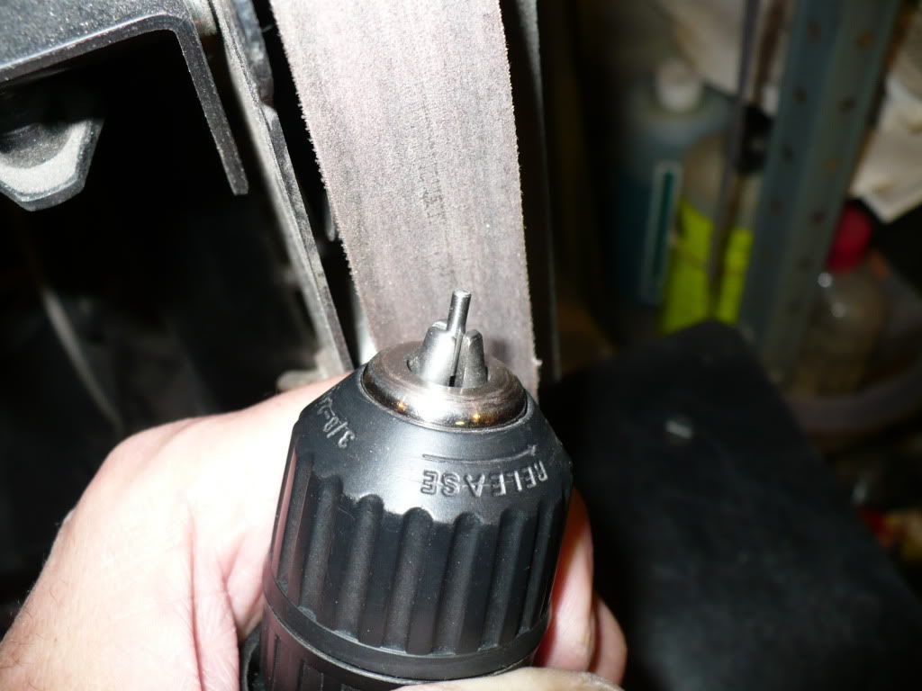
In the picture below I'm machining the 'valve guides'. A pretty simple operation, but the holes needed to be carefully reamed, and will hopefully be concentric with their outer diameter's. If they are off a bit, or go-off a bit during assembly (its possible), then the valve seat cutter will do its job, and solve the problem by cutting a seat that's concentric with the reamed holes in the valve guides.


P1040478.jpg


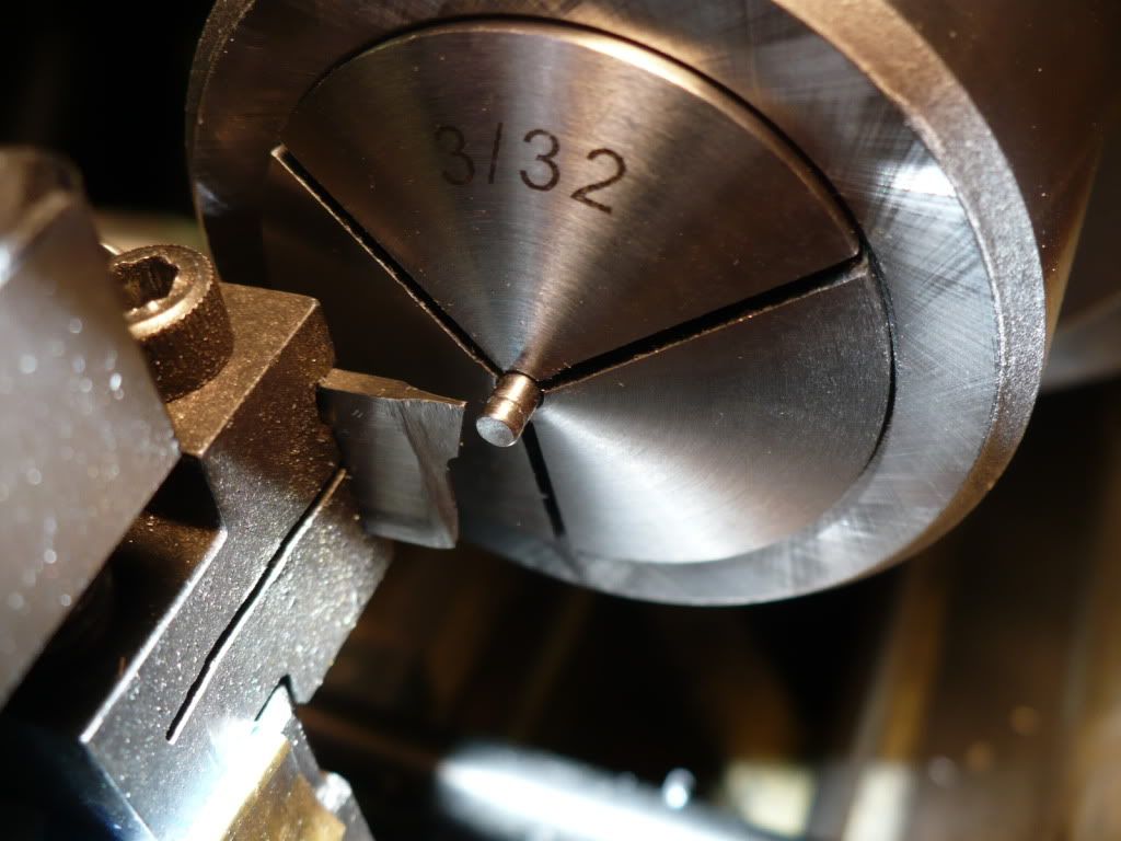
144) I broke the sharp edges on the reamed holes, test fitted a piece 3/32" drill to check the bores, and their done.

P1040482.jpg


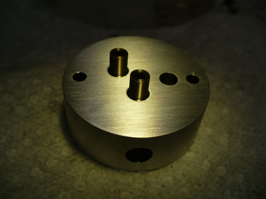
145) Here I'm testing their fit on one of the heads. And they feel like a perfect fit. I love it when parts fit, its like frosting on a cake.

P1040487.jpg


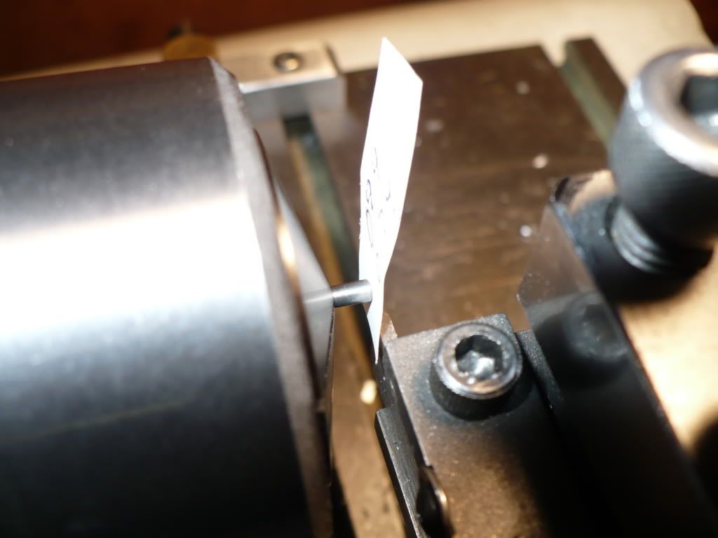
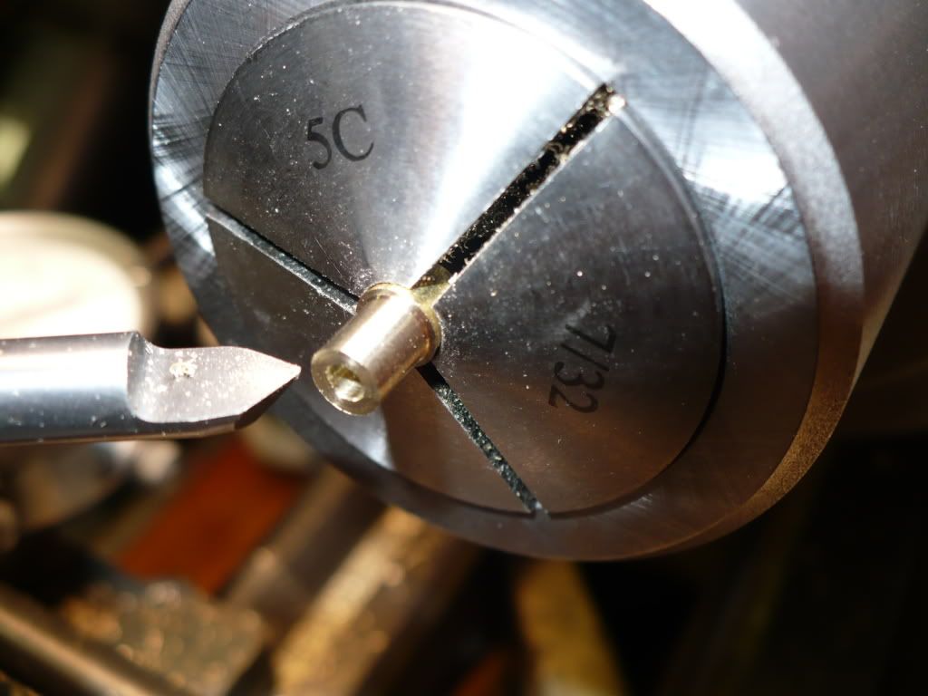
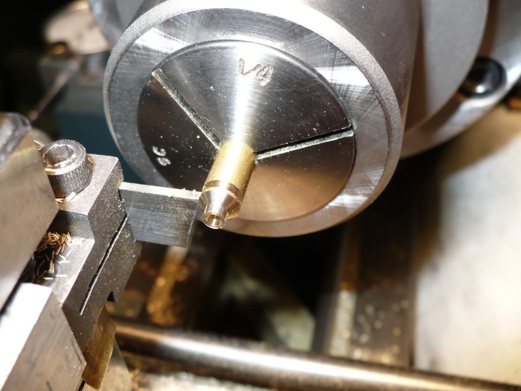
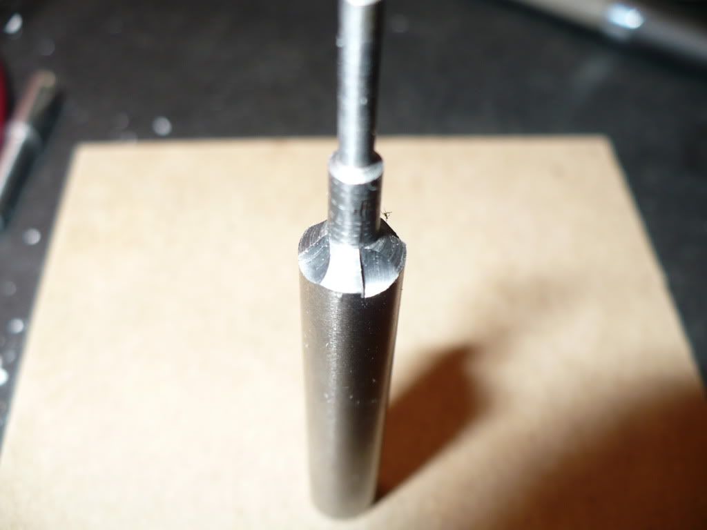
146) In the picture below I'm cutting off one of the valve steam heads.

P1040500.jpg


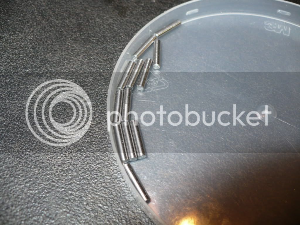
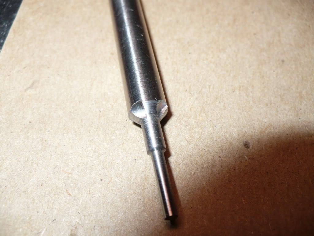
147) I only need 10 finished valve stems. With the set up and moves all worked out, it was quick and easy to make a few extras.

P1040512.jpg


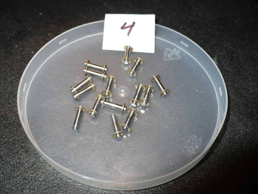
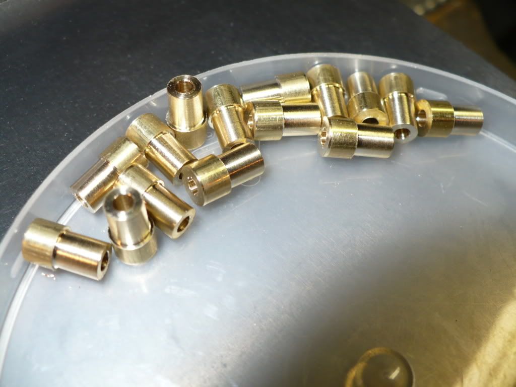
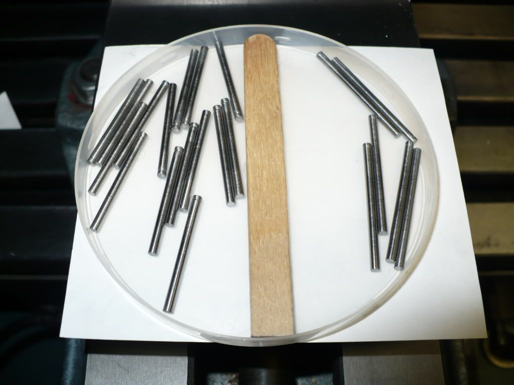
148) I cut the valve stem rods a little over size and ground them on my belt sander to plus .002" minus .000" of the specified length. The smaller batch on the right, are the longer ones used on the F-head engines. Its hard to see the cut grooves for the retaining clips.

P1040517.jpg


149) Here's where I shine. I like to braze, but I hate the clean-up! I try to be very careful but it doesn't seem to matter in the end. I only managed a few pieces as 'picture guy' was in a big hurry to go sliding around on the snow covered streets of northern Ohio with his car.

The brazing went well. Here's how I did it. I created a 'moat' for the silver brazing material by opening up the top of the hole in the head with 8 twists of a countersink, about .020". And used 2 twists at the smaller bottom end. I beveled the valve stem 'rod' 10* to 15*, and about .020" wide. Since the rod is a slip fit into the head I scribed it with about 5 or 6 lines length wise and only where the head will sit. This creates a sort of light press fit to secure and equally space the head on the rod to allow for the braze to flow completely around the joint. All the surfaces were fluxed before assembly. I wrapped the brazing rod around a valve rod to create a sort of spring and cut single loops. The single loops were then cut in half and compressed, and only a half loop was used on each stem assembly. With the assembly standing head up, it was fluxed again and the small piece of braze material set on top and in the middle of the rod. I applied the heat to the lower intersection of the rod and base, at the base of the head. I didn't take much heat at all using a standard propane torch, to make the brazing flow down and though the entire joint.

P1040522.jpg


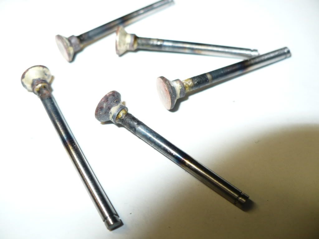
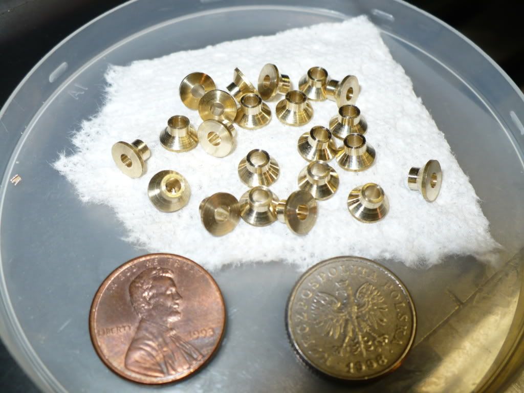
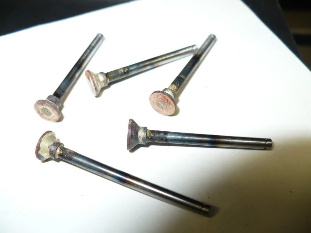
150) The 'moat' worked like a charm to keep most of the brazing off the top of the valve head where it's not needed. The silver brazing rod I used was .031" in diameter. If I had used a larger diameter rod, a square cut 'pillow' would have been sufficient to fill the small gap in a tight joint like this. Its easy to create flow, as it always runs towards the heat source. If you look real close, you can see that the brazing reached and emerged at the intersection between the head and the rod indicating a good solid joint.

P1040524.jpg


151) I started on the 'valve seat cutter". I'm still stumped on how to create the relief. scratch.gif

P1040525.jpg


152) Same cutter, different angle.

P1040530.jpg


That's all for today, hope you enjoyed my post. :)

-MB
 
I set my cutter up in the mill vice and used a small file to cut the relief in--this of course was before any hardening. Its not very difficult---you have to file in a circular motion, taking care not to run into the cutting edge behind the one you are filing, and to start your stroke with very light pressure, increasing the pressure as you sweep the file around/across the part. What you HOPE to do is not cut any metal right at the cutting edge, but to cut more and more behind the cutting edge as your file sweeps around under ever increasing pressure. Not a very exact science, but lacking the equipment GBritnell has, its the only way I could think of----and I was desperate!!! It seems to have worked okay, because when I cut my brass valve seats with VERY light hand pressure, I ended up with small brass filings on each cutting edge of the cutter. If any one edge had been out very much, it wouldn't have shown the chips.
 
Hi Brian. It looks like using a file is my only option at the moment. It seems like a barbaric method that won't have a happy ending. One miss placed file stroke and the cutting edge is toast.

-MB
 
You have the choice of joining Brian the Barbarian or buying more sophisticated equipment the equal of G Britnells and learning how to use it. ;D ;D ;D And you're right---it is a bit barbaric. I hate doing any kind of machining process that I can't measure or quantify in some way. You didn't see it in any of the pictures I posted, but the other end of the tool I machined was done first---it turned out perfect except it "grew" just a teensy bit in the middle of that 0.093" section---enough that I was afraid it would damage the inside of the valve guides if I forced it. So I set it up in the lathe and took my sharpest carbide tool---just shaved it a cats whisker---and the entire .093 tip snapped off like glass. I said a few choice words and then popped the hardened end of the tool into the chuck and machined it all over again at the other (still soft) end, and then hardened the second end. I was so desperate that I made the tool as a sort of last resort mode---and even then I had no compression untill I lapped each valve with 350 grit,600 grit, and then toothpaste.
 
Many many moons ago, somewhere in the mid 70's, my auto mechanics instructor taught me to grind the seat at one angle and the valve about 1 degree less. You then lap the valve until you have a continuous ring around the valve, that way you know the valves will seal. I can't see why the same process can't be applied here.

Long time lurker,
Don
 
ddmckee54 said:
Many many moons ago, somewhere in the mid 70's, my auto mechanics instructor taught me to grind the seat at one angle and the valve about 1 degree less. You then lap the valve until you have a continuous ring around the valve, that way you know the valves will seal. I can't see why the same process can't be applied here.

Long time lurker,
Don

I'm sure it could be, and its been done either accidentally or on perpose by some. If the seat on one of these small engines with 1/4" valves is a very small one, say about .010" to .015", than that should be enough to make a good seal with a very light lapping.

-MB
 
Brian Rupnow said:
So I set it up in the lathe and took my sharpest carbide tool---just shaved it a cats whisker---and the entire .093 tip snapped off like glass. I said a few choice words and then popped the hardened end of the tool into the chuck and machined it all over again at the other (still soft) end, and then hardened the second end.

Brian. A while back I posted that the cutters should be 'drawn back' meaning slightly annealed after hardening, and some of the members disagreed, saying it wasn't needed. I vowed not to say any more about it on that thread.

I did a small amount of heat treating a long time ago and learned quickly, that you do not want to drop a tool or part in its fully hardened state. I did, and when it hit the concrete floor I found out how brittle it really was. It's as brittle, or more, than a glass object of the same size and shape. Its important to understand that the thin sharp honed edges on a cutting tool are very susceptible to chipping if they haven't been properly annealed. As an experiment, cut two pieces of 1/4" rill rod 1" long and harden both in the same manner. Clean them up with emery paper. Draw one back by heating it up till it turns yellow and at just a hint of blue quench it again. Put on heavy shop clothing to protect all exposed skin, wear heavy welders gloves, and a full face shield. Give them a few good taps with a hammer to see which one cracks first, and to see how easy it was to crack it. In this contest the 'hard' guy looses.

To anneal, a part or tool is cleaned up bright, and heated till it reaches a certain color, and then its quenched again. Drawing back is a very simple process that only takes a few minutes. I would not leave out this very important final step.

-MB
 
Barbaric, barbaric!!! And here I thought all those years of filing I did was something of an art form. Come on guys, you can't let endmills do all the work for you. Sometimes you have to get your hands dirty a little.
Rick, do the Upshur plans call for brass heads on the valves? When we talked I just figured you were going to make them out of the same material as the stems.
George
 
gbritnell said:
Barbaric, barbaric!!! And here I thought all those years of filing I did was something of an art form. Come on guys, you can't let endmills do all the work for you. Sometimes you have to get your hands dirty a little.
Rick, do the Upshur plans call for brass heads on the valves? When we talked I just figured you were going to make them out of the same material as the stems.
George

Hi George. When 'you' work the files with your talented hands the results are a form of art. :bow:

When 'I' work the files with my unsure hands the results are barbaric. Rof}

Plans? The plans call for creativity! Please don't tell me I messed up by using brass for the valve heads. :Doh:

-MB
 
Hi Rick,
??? ??? ???
George
 

Latest posts

Back
Top