MB building Upshur Farm Engines.

Home Model Engine Machinist Forum

Help Support Home Model Engine Machinist Forum:

This site may earn a commission from merchant affiliate links, including eBay, Amazon, and others.
Metal Butcher said:
#186 Did I get you to start thinking, " this guy is nuts, you can't drill a square hole." Ah! But you can fake it by making the muffler out of two pieces, and milling two cross slots with an end mill on the lower half that's threaded onto the pipe. The upper 'cap' is then soldered on, and a light truing cut on the O.D. in the lathe, helps to conceal the joint line.

Nicely done :bow:
 
We're still eating left over Christmas gobbler
And here you're complainin' and wantin a wobbler.
Give up the machining and become a cobbler!!! ;D ;D ;D
 
MB,

When you get to broaching your flywheels, could you take a bunch of pics and either post them here or email them to me? I never seen it done, and if I ever get to one of the geared loco's I want to build, there is a ton of gears that need to be keyed. I want see how that is done the right way. :big:

Matt
 
Brian Rupnow said:
We're still eating left over Christmas gobbler
And here you're complainin' and wantin a wobbler.
Give up the machining and become a cobbler!!! ;D ;D ;D

Excellent Brian! Hope that bird was still good. I'm glad to meet a fellow shop poet! Thm:

I also like to sing and dance around the shop, mostly operas. My performances are based around the tragedy of a hopelessly inept apprentice, torn by his desire to gain the illusive approval of his talented peers. It a very moving performance. :'(

I would post a video in the 'break room' but my modesty precludes me. Rof}

-MB

 
1hand said:
MB,

When you get to broaching your flywheels, could you take a bunch of pics and either post them here or email them to me? I never seen it done, and if I ever get to one of the geared loco's I want to build, there is a ton of gears that need to be keyed. I want see how that is done the right way. :big:

Matt

Sure Matt, more than happy to oblige. I'll be sure to post a step by step with pictures, on how I broach a key way. Thanks for asking.

All I have to do is some research, to see how its actually done! ;D

-MB
 
#187 I was not sure if I should add oilers to my engines. Since I have a lot of oilers to make, the use of glass did not appeal to me. After a little digging around on the internet I found a plastic substitute worthy of a try. Not only is this material inexpensive, its also seemed relatively safe to machine. How it holds up to oil remains to be seen. I ordered four sizes to cover all the possibilities, 1/4, 5/16, 3/8, and 1/2". If you order any beware that its sold in 6 FT pieces. Since its so inexpensive I failed to notice that it was 6ft, not 6 inches, and thinking 2 ft of each, nearly ordered 24 ft of each size! :big:

http://www.eplastics.com/Plastic/Extruded-Plexiglass-Acrylic-Tubing

Below I'm cutting off a 1/4" piece of the 5/16" diameter tubing that I decided would be about the right size for the crank shaft oilers. The material is thick and easy to machine. I cut off slowly, since I didn't know how the stuff would behave. It went well, and I didn't have any problems.

P1040738.jpg


#188 A step .050 long x the I.D. of the tube was machined on 5/16" diameter brass stock. In the picture I'm reaming the hole through the base part of the oiler for a threaded 1/8" tube.

P1040741.jpg


#189 I cut off the base leaving 1/16" material, this will be outside of the tube.

P1040742.jpg


#190 The first end of the 1/8" tube was drilled #56 x 1/8" deep. After the tube is threaded, cut off, and reversed in the collet, a 1/16" hole will be drilled to meet up with the #56 hole drilled from the first end.

P1040746.jpg


#191 After drilling the other end 1/16", and threading it 5-40, the 1/8" brass tube is cut off.

P1040749.jpg


#192 I made two sizes to see which would look better. I think the shorter ones with the 1/4" long glass and 1/2" long tube look the best. I'll try other ideas including making a few prototypes of cylinder oilers over the next few days.

P1040756.jpg


These were very simple, and a lot of fun to make. As far as I'm concerned, eliminating the use of glass made these much easier. If I were building a museum quality true to scale model, then the use of glass oilers would be a must.

-MB

 
MB,

They look awesome! I can't tell the difference, and I'm sure they where alot easier to make, then using glass.

Great Idea........"mental note #1341...... plastic tube for oilers" :big:

Matt
 
#193 Over the last two days I finished up enough 'oiler' parts to cover the five Upshur engines I'm building. The plans call for a plain oil hole added to the side plates above the crank shaft bushings. The idea behind my 'oilers' is to add a little visual interest to a somewhat basic design. In the picture below are all the parts I made for the crank shaft oilers. I made a few extra just in case.

P1040765.jpg


#194 Below is a picture of the 'cylinder oiler' parts I made using the same design as the crank oilers, I made them slightly larger by using 3/8" tubing. The oilers are far from being finished. They need to be assembled with clear silicone, and the threaded tubes need to be secured to the brass bases with Loctite or soft solder. If I use these on the two planned vertical versions, I will need to make some sort of 90* fittings, or use 1/8" elbows if they exist.

P1040770.jpg


It seems like I'm making this simple project more and more complicated. :Doh: *bang*

-MB

 
Metal Butcher said:
I will need to make some sort of 90* fittings, or use 1/8" elbows if they exist.

PM Research has 'em here

You sure are zipping along with this, and they are looking good!

Cheers, Joe
 
Rick---I haven't seen that anyone else has asked the question, but why are you building so many? Are you planning to sell some of them? I know that with the time I have invested in even one of my small engines, someone would have to trade me even for a small island in the Carribean before I'd feel that I was fairly compensated.----Brian
 
joe d said:
PM Research has 'em here

You sure are zipping along with this, and they are looking good!

Cheers, Joe

Thanks Joe! Yes, I see they do carry them. When I was at the NAMES show 2 years ago I asked about them for future projects. At the time I was planning on building some of Elmer's Engines, and could have used this smaller size. One of the guys at the PMR table said they didn't make anything smaller than 3/16". I could have really used them on my 'Turkey" build, a three cylinder wobbler designed by Elmer Verburg. Bending up all the tubing was a nightmare.

Thanks again Joe.

-MB
 
Brian Rupnow said:
Rick---I haven't seen that anyone else has asked the question, but why are you building so many? Are you planning to sell some of them? I know that with the time I have invested in even one of my small engines, someone would have to trade me even for a small island in the Carribean before I'd feel that I was fairly compensated.----Brian

Those are some very good questions Brian! woohoo1

Why am I building so many?

I ask 'myself' that one with increasing frequency. I guess I was mesmerized by the plan set which allows for at least 10 different versions. Ten seemed a bit much, so I decided on building a paltry five versions. The challenge was also appealing to me. :noidea:

Am I planning on selling some? No, never was. Fact is, Its doubtful that I could get back the money I invested in this project so far, and its not over till the gas fumes explode. Rof}

Was it a good idea? Probably not and I'm starting to question my own sanity. scratch.gif
 
been following the progress with geat interest as I am about to start on 1 myself. I am ordering the required materials this week, 5 at a time taxes my remaining grey matter so 1 at a time will do me. ;D. I have a question for you regarding the size of initial block you made the body from as I reckon thats the way I will go rather than assemble it.
Keep at it as I love the way you are doing it not to mention the speed. :) Am waiting to see how you tackle the valve seats too.
Cheers
Pete
 
I had noticed those oilers a couple of days ago and thought I'd made a post. Sorry about that. They look great and I'll be interested to see how the plastic holds up over time.

Metal Butcher said:
and I'm starting to question my own sanity.

You are not alone. ;D
 
hopeless said:
been following the progress with geat interest as I am about to start on 1 myself. I am ordering the required materials this week, 5 at a time taxes my remaining grey matter so 1 at a time will do me. ;D. I have a question for you regarding the size of initial block you made the body from as I reckon thats the way I will go rather than assemble it.
Keep at it as I love the way you are doing it not to mention the speed. :) Am waiting to see how you tackle the valve seats too.
Cheers
Pete

Hi Pete, Thanks for taking interest in my project. Its good to hear from another person building the same engine. Building 'one' is a good idea, building a gang of them (of any first build) can become problematic. The good news is that I'm starting to really enjoy the conversations I have with myself. :rant: Rof}

I started with an oversize saw cut block of 6061 aluminum. A good size to start with is 2" x 2" x 2-1/2", or use what ever you feel is appropriate. I measured up my finished water hopper and the final dimensions are 1.937" x 1.500" x 2.250". These are the exact measurements of the built-up hopper on page 4 of the plans. The top plate (cover) is 1.937" x 1.500" x .250".

Feel free to ask questions any time you feel a need for some advise. I'll be more than happy to help out . As with most plans there will be parts that might need an explanation, and dimensions that seem to be missing once you start machining the parts.
I can look at plans sveral times and never see the problems that become apparent once I start machining.

-MB
 
zeeprogrammer said:
I had noticed those oilers a couple of days ago and thought I'd made a post. Sorry about that. They look great and I'll be interested to see how the plastic holds up over time.

You are not alone. ;D

Hi Zee. I really don't think there will be a problem with oil in contact with the Plexiglass Acrylic Tubing. I thought about it, and it seems that most everything these days is packaged in some sort of plastic, like paint thinner, trans fluid, oils, vodka...yea vodka!

Too early in the day :'(

-MB
 
Metal Butcher said:
it seems that most everything these days is packaged in some sort of plastic, like paint thinner, trans fluid, oils, vodka...yea vodka!

But the vodka never stays in the bottle long...or shouldn't.

Yeah...you're right. Should be fine.

 
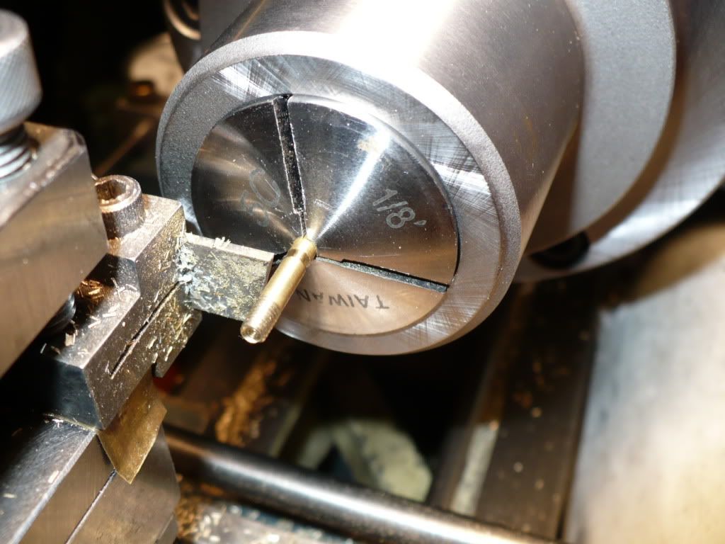
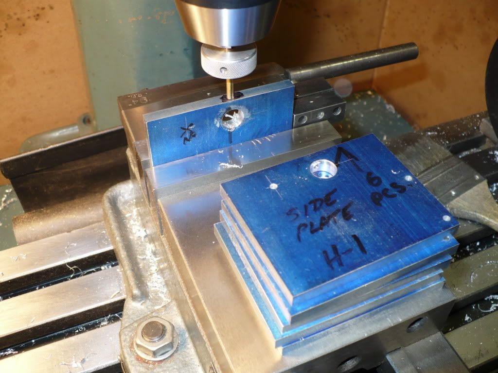
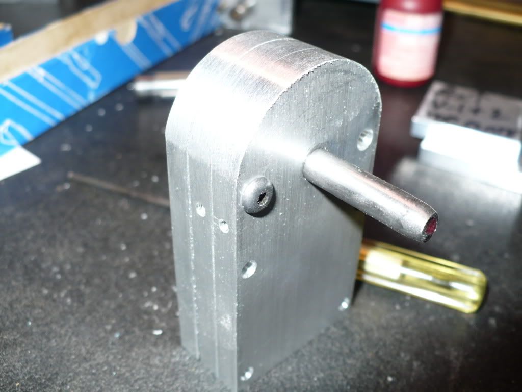
#195 I managed o get a little more done over the last two days. Seems that there's always something that gets in the way of having a full day down in the shop. I was getting a little tired of making small parts so I decided to start drilling and tapping the plates that were cut at the start of this thread.

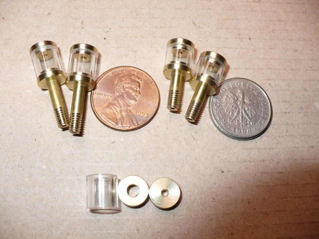
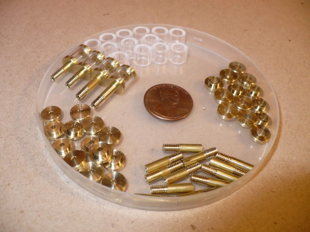
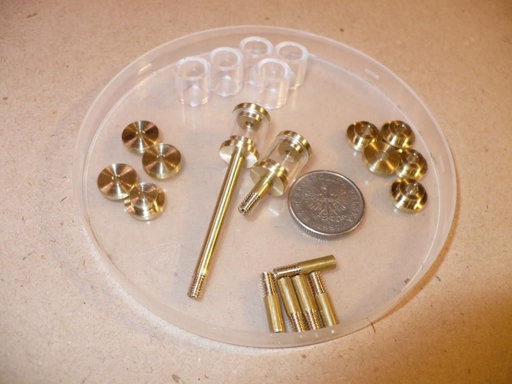
Below are the side plates for the three horizontal versions. I'm tapping for the crank oilers I made in the last post.

P1040772.jpg


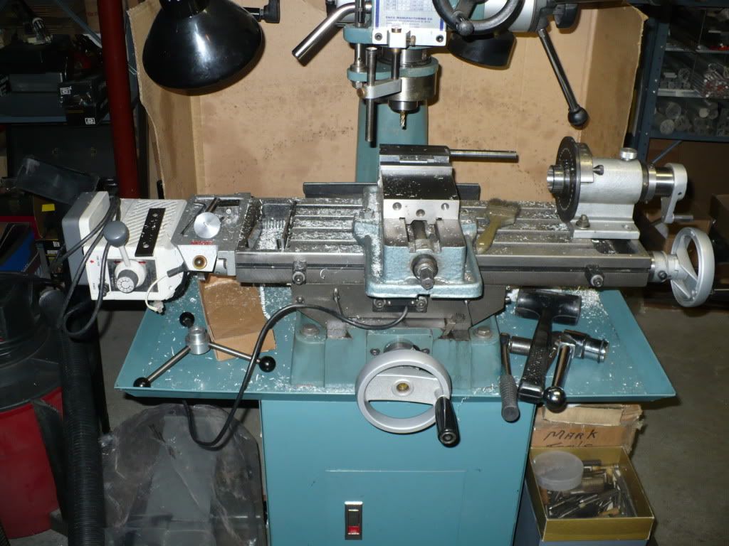
#196 I threw in a picture of my messy M/D. I don't want any one to think that I'm fussy about neatness. :eek:

P1040774.jpg


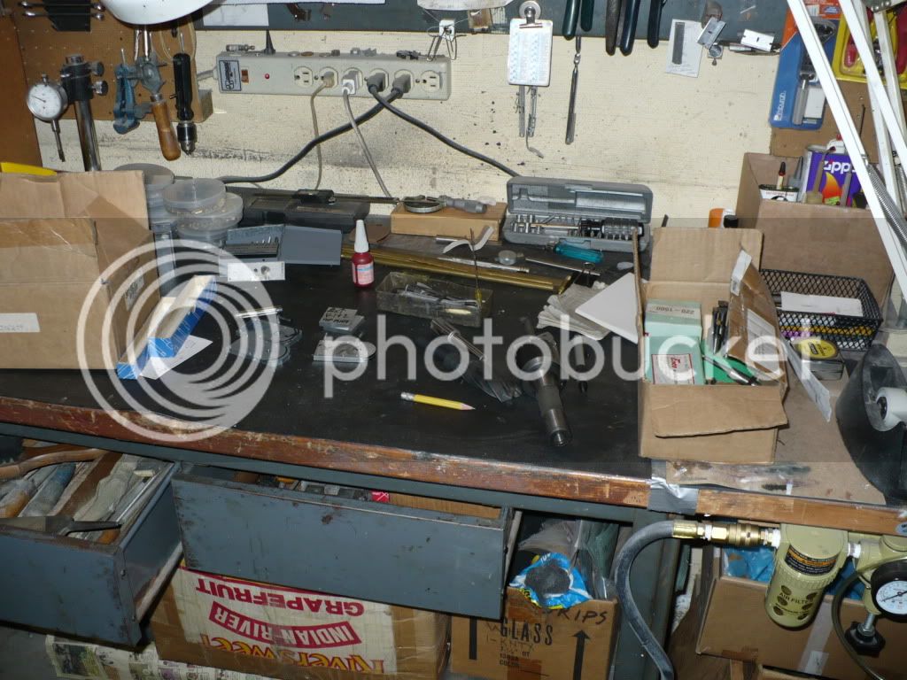
#197 And the way my bench looks every day of the week. ::)

P1040775.jpg


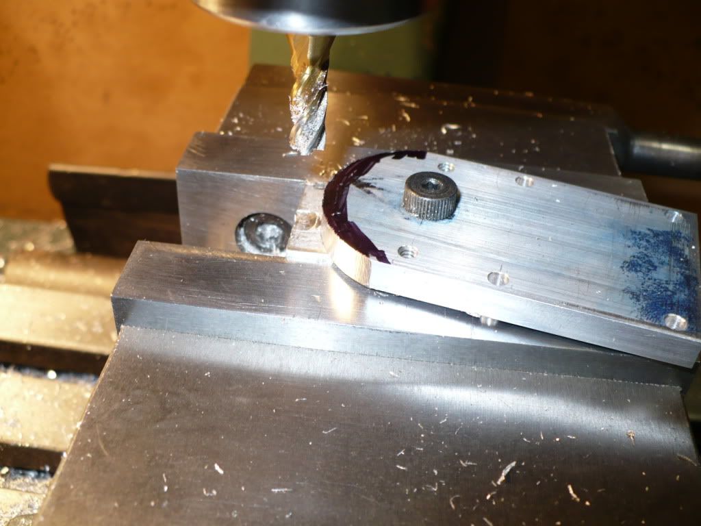
#198 After drilling and tapping the holes on the front plate I added a reamed 1/4" hole central to were the cylinder bore will go. Using a shoulder bolt Loctited snugly in place to a scrap block it became a pivot point to create the radius at the top of the front plate. I cut off most of the excess with the band-saw leaving only .030 to .040" to be milled off. I rotated the work into the cutter, and swung the work back to the starting position only after raising the cutter. This was necessary to avoid a 'climb cut' that would likely pull the work right out of my grip. And then I advanced the table towards the cutter by .005" (five thousands only!) This is not a great way to do this, and I do not recomend it. Due to the size of this radius its safer to use a rotary table, or by grinding up to a scribed line using a belt sander.

P1040778.jpg


#199 I took the opportunity to save some time by fileing all three at the same time, to remove the milling marks.

P1040780.jpg


#200 Wow, two hundred pictures! Hope I'm not boring you with too many pictures. ::)

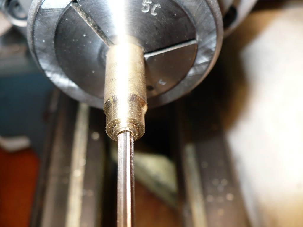
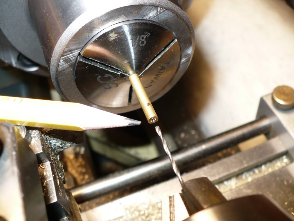
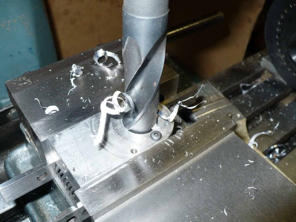
Below I'm preparing the front plate by drilling it before using the boring head to bring the hole to final dimension. I started with a long #5 center drill followed by a S/D 5/8", and a S/D 27/32" drill. Slow speed was the key to avoiding the chatter that can lead to some serious problems. I used 440 rpm by switching around the drive belts.

Up until recently I used only one speed and put up with the chatter, the bolts on the mill un-screwing, drills falling out of the chuck, every thing hitting the floor, you know.. the usual 'idiotic rookie' type stuff.
Rof} Rof} Rof}

P1040783.jpg


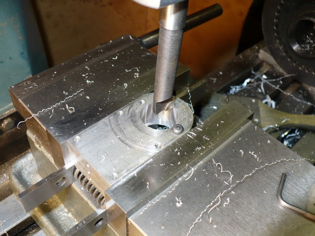
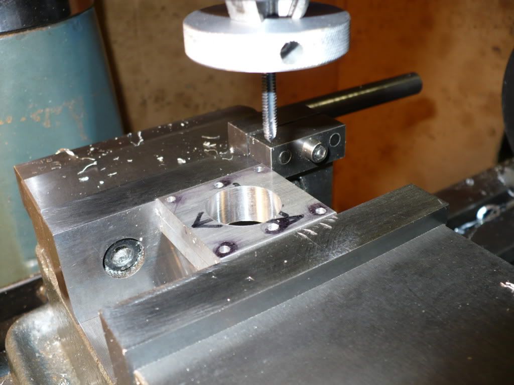
#201 I finished up the front plate by bringing it to final dimension using a boring head, using the same slow speed left a nice smooth finish, and I didn't have to deal with hair raising chatter.

P1040784.jpg


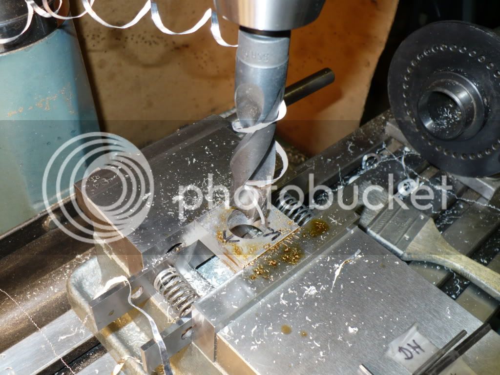
#202 Since all the tools were out, and my hands were dirty, I decided to bore out the top plate's that support the cylinders on the vertical versions I'm also building. The bores came out nice and smooth, and the cylinder's fit real nice.

P1040787.jpg


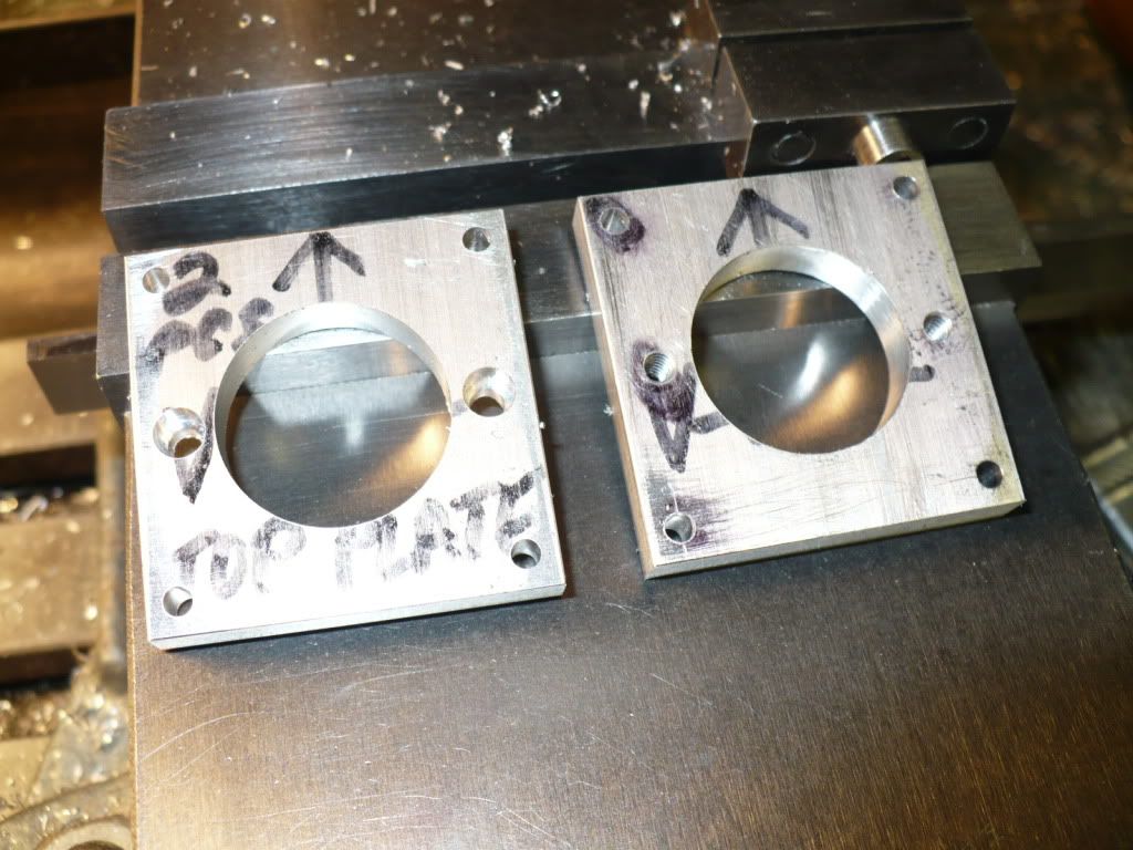
#203 I finished up the top plates by adding the drilled and tapped holes.

P1040789.jpg


#204 In this picture you can see the two counter bored holes in the left plate that's used on the vertical 'F-Head' version. The plate on the right with the two threaded holes is used on the vertical air cooled version. It can get confusing at times making parts for all of the different versions. :Doh:


P1040790.jpg


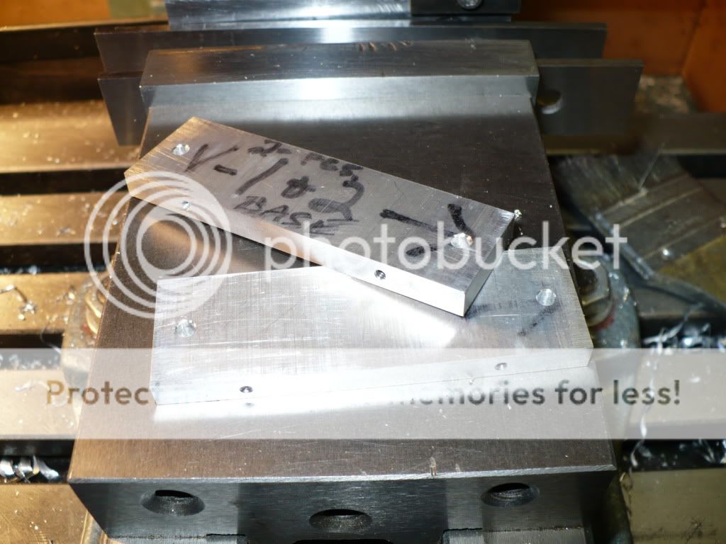
#205 The two bases for the vertical versions were also drilled and tapped.

P1040792.jpg


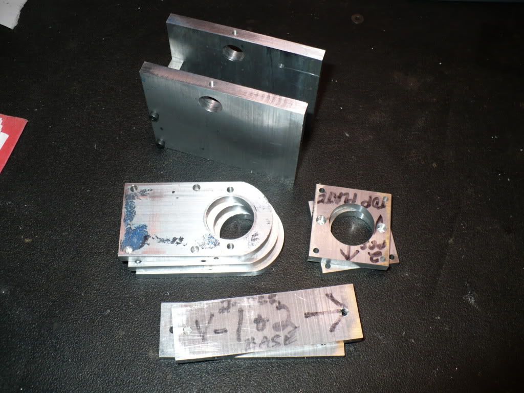
#206 This picture shows most of the parts I just finished up. I forgot that there were some sitting on my other bench.
I'll work on drilling and tapping the side plates for the two vertical versions over the next few days, and the side plates I showed in the beginning of this post need their simple profile milled.

P1040794.jpg


-MB
 
Back
Top