MB building Upshur Farm Engines.

Home Model Engine Machinist Forum

Help Support Home Model Engine Machinist Forum:

This site may earn a commission from merchant affiliate links, including eBay, Amazon, and others.
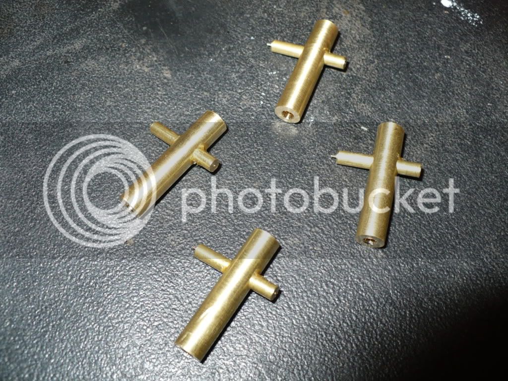
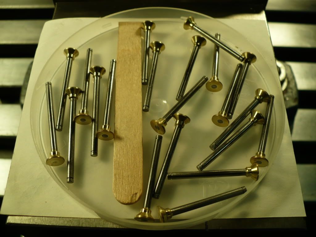
153) I finished brazing all of the valve stem assemblies

P1040532.jpg


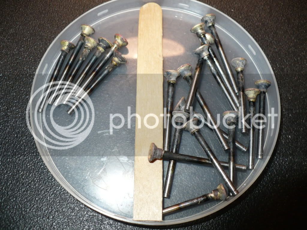
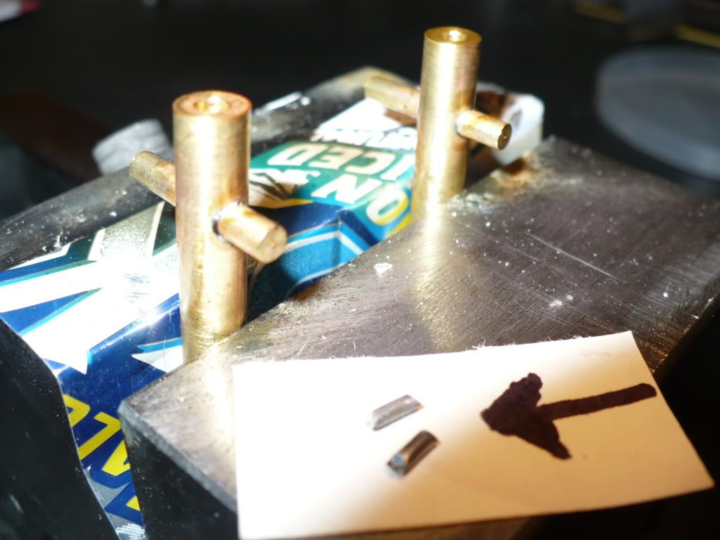
154) The mess left by the brazing was cleaned up, and the seat area was trued up using a collet held bushing made specifically for this purpose.

P1040537.jpg


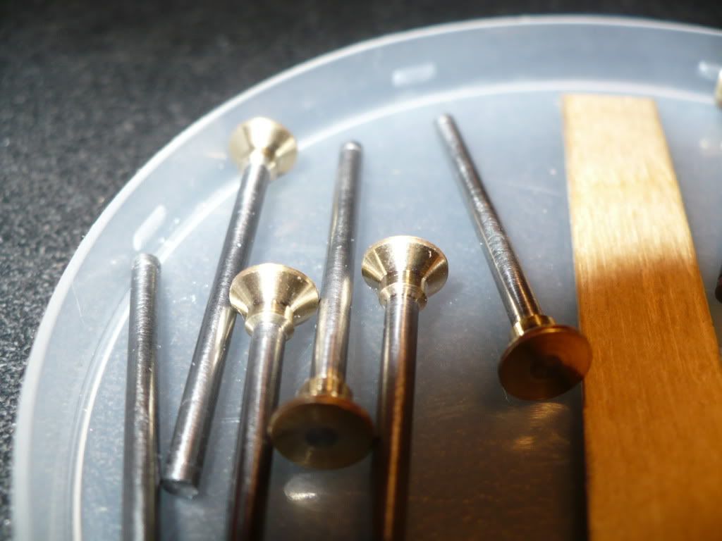
155) Here's a close-up of the valve stems

P1040542.jpg


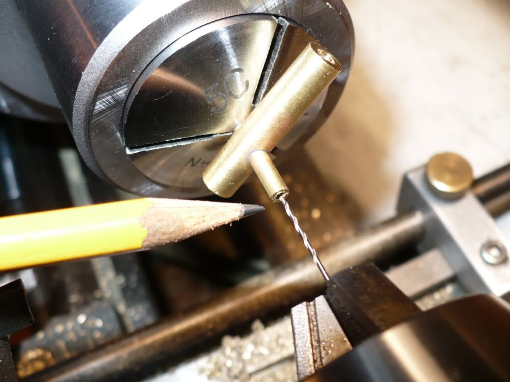
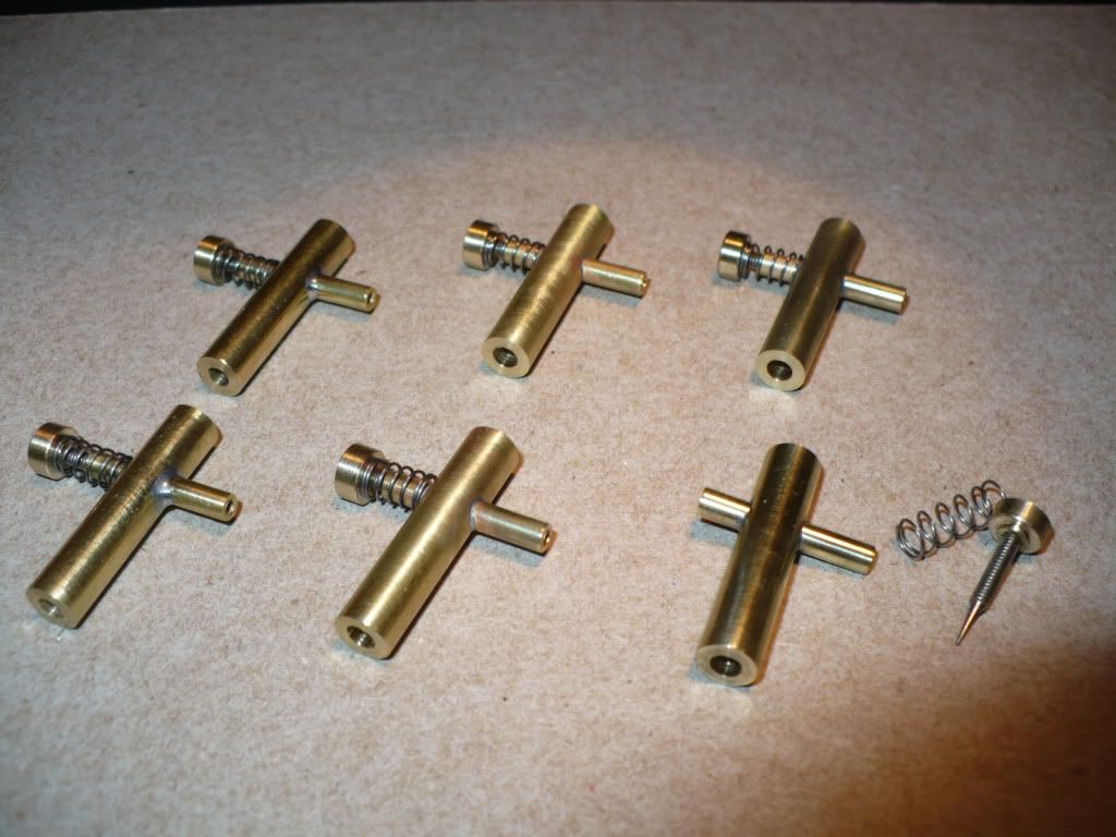
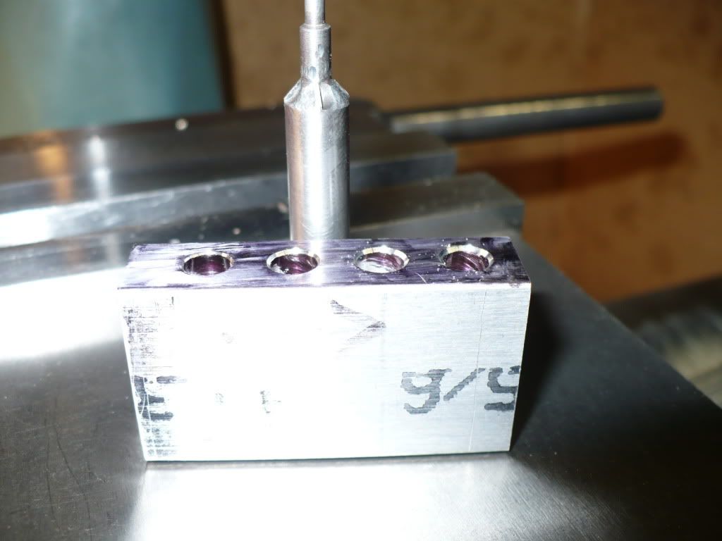
156) I used a grinding stone held in my Dremel tool to cut the relief on the valve seat cutter. after heat treatment the cutting edge was stone sharpened. It was much quicker and easier than I had thought. I drilled and reamed a test block for the cutter duplicating the dimensions and free space under the valve seat.

P1040571.jpg


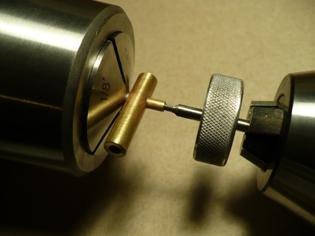
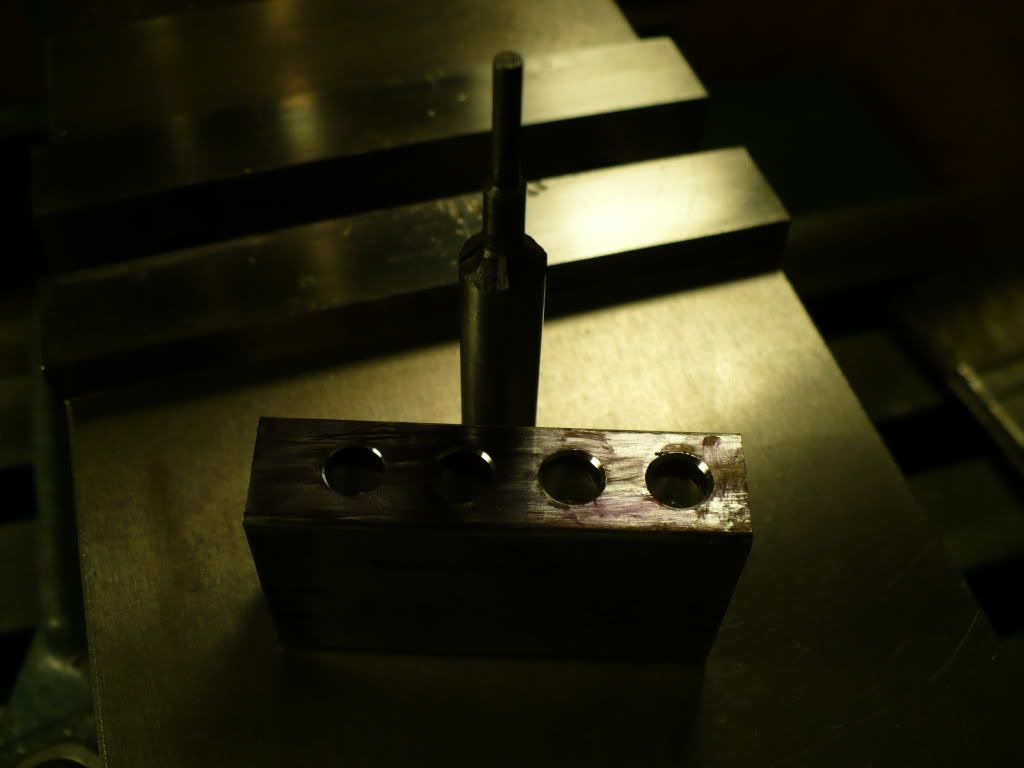
157) I trial cut four seats to different depths. The tool cuts very fast. and gives a nice clean smooth seating surface. To my surprise the cutting action is much faster than any my factory made countersinks.

P1040574.jpg


158) Starting over I made 10 new valve stem 'heads' from steel. It was brought to my attention that brass was not the best choice for the exhaust valves. Apparently the heating and cooling causes thermal shock which brass does not hold up to very well.

P1040581.jpg


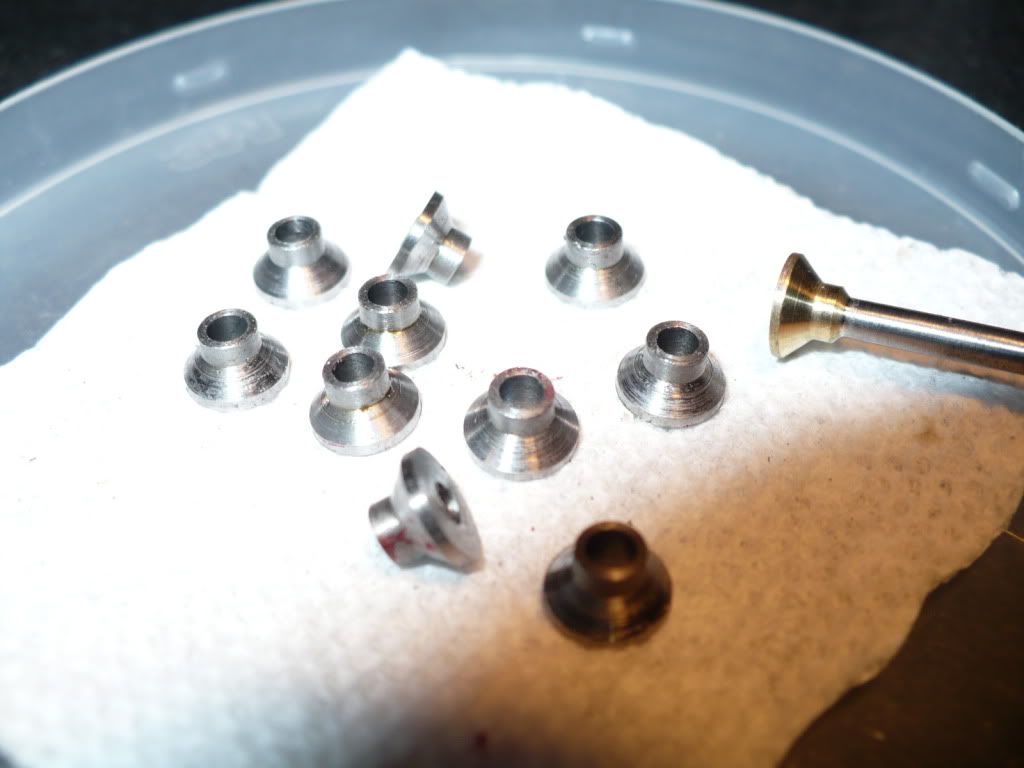
I'll make up new stems, braze up the valve stem assemblies, and true up all the surfaces on the valve stem heads.

-MB

 
Brian Rupnow said:
Ha---Knew you could do it-----Barbarian!!!!

Hey Brian, it took me only a few minutes using the Dremel! Thm:

And I didn't even get my hands dirty! stickpoke

Rof} Rof} Rof} Rof}

-MB


Metal Butcher said:
158) Starting over I made 10 new valve stem 'heads' from steel. It was brought to my attention that brass was not the best choice for the exhaust valves. Apparently the heating and cooling causes thermal shock which brass does not hold up to very well.

Bummer! But good to know. Still, the cleaned up stems look impressive. It surprises me how well things clean up after brazing.

When you found out...are you the type of guy whose shoulders sagged a bit, you mumbled a 'drat', and then went on? Or the type of guy that causes parents to place their hands over their childs' ears?
 
zeeprogrammer said:
Bummer! But good to know. Still, the cleaned up stems look impressive. It surprises me how well things clean up after brazing.

When you found out...are you the type of guy whose shoulders sagged a bit, you mumbled a 'drat', and then went on? Or the type of guy that causes parents to place their hands over their childs' ears?

Hey Zee

I usually mumble a word or two and, get right back to it.

Drat? No, my vocabulary is considerably advanced. ;D

-MB
 
Rick--If I might ask, what is the cylinder bore and stroke of the engines you are building? I am considering building an Upshur carburetor for my engine, because I can not get it to run consistently.The bore through the Upshur carburetor is 0.125 or 0.156 depending on which plans you have (mine are an early set--1977) The Kerzel is a 3/16" and 1/4" bore through the carb. The Kerzel is 3/4" bore x 0.8" stroke.
 
Brian Rupnow said:
Rick--If I might ask, what is the cylinder bore and stroke of the engines you are building? I am considering building an Upshur carburetor for my engine, because I can not get it to run consistently.The bore through the Upshur carburetor is 0.125 or 0.156 depending on which plans you have (mine are an early set--1977) The Kerzel is a 3/16" and 1/4" bore through the carb. The Kerzel is 3/4" bore x 0.8" stroke.

Brian, the Upshur bore is .750" with a 1.000" stroke.

1) Carburetor assembly with optional throttle, page 16A dated 8-1-96, .187" diam thru bore.

2) Carburetor assembly, page 15 dated 7-8-77, .125" diam thru bore.

Carb's looks easy to build, go for it, its worth a try.

-MB


My drawing says July-77 and calls for a .156 bore thru. Maybe Hamilton rethought that and shrunk it down to 0.125. I don't know if 7-8-77 is the 7th of august or the 8th of July.
 
Brian Rupnow said:
My drawing says July-77 and calls for a .156 bore thru. Maybe Hamilton rethought that and shrunk it down to 0.125. I don't know if 7-8-77 is the 7th of august or the 8th of July.

That's interesting, your drawing says "July 77" and mine says 7-8-77. Here In the States 7-8-77 means July 8th 1977, And Hamilton lived in Pennsylvania, USA.

You could make two with everything identical except the bores. One with .125" bore and the other with a .187" bore. And then try out both using the same, one and only needle.

I wonder if all the other dimensions are the same. If it doesn't infringe on the 'copy write' post a drawing or dimensions of the "July 77" carb.

-MB
 
Brian;
My drawing set shows the same info as MB has stated. Dates are the same as his also. As an additional data point for you Hamilton's flat opposed twin engine uses the same carb as drawn on page 16A of his Farm Engines drawing set (0.187in. thru bore). The outlet is simply branched to feed the two cylinders. The twin's are 0.75in. bore and 0.72in. stroke.
Cheers
Garry
 
A few years ago I ordered the four issues of Strictly IC Magazine (#77-80) for the Upshur plans. Those drawings are dated July, 1977 and show the carburetor bore as 0.156. Since the magazine series did not include the hit-and-miss governor option, I then ordered the plans from his daughter to get the governor drawings. The drawing for the carburetor assembly is dated 7-8-77, and shows the carburetor bore as 0.125. That's what I used.

Rudy
 
rudydubya said:
A few years ago I ordered the four issues of Strictly IC Magazine (#77-80) for the Upshur plans. Those drawings are dated July, 1977 and show the carburetor bore as 0.156. Since the magazine series did not include the hit-and-miss governor option, I then ordered the plans from his daughter to get the governor drawings. The drawing for the carburetor assembly is dated 7-8-77, and shows the carburetor bore as 0.125. That's what I used.

Rudy

Hi Rudy, I started on the basic version of the carb's yesterday, and used .125" as the main bore with a reduced area at the intersection of the cross bore, where the needle and jet are located. My plans also include a larger bore carb with a 'barrel' that houses the needle and jet. The barrel can be rotated to reduce the size of the venturi. Its good to hear that you used the .125" bore. I watched your video several times and it's obviously a carburator that works.

Edit: I just realized that your avatar picture is a model of the Upshur air cooled horizontal! Very nice!

-MB
 
Thanks MB. I also built that barrel-type carburetor per the plans as a learning experience and tried it just to see how it performed. Worked pretty good, I was able to throttle it down pretty slow. But I prefer the hit-and-miss. Looking forward to watching yours in action.

Regards,
Rudy
 
159) For today's post I made the carburetors for my Upshur Farm Engines project. yesterday I made up two carb assemblies and forgot to take pictures. It doesn't really mater since I made four more today, shown in the picture below. After soldering up the first two I changed my approach on the next four. First I drilled .093" all the way through them to create a smaller diameter venturi area at the needle valve/jet area. The .093" bore will be used as a convenient way to add the flux and solder. The first two were assembled by adding solder to the joint from the outside. This method left a noticeably uneven fillet joint.The .125" bore will be added later by drilling from both ends and leaving a 1/8" section at the needle valve .093" to create the venturi.

P1040586.jpg


160) I fluxed the pieces and assembled them in my all purpose vice for soldering. More flux was added down the bore, along with a pillow of solder. I heated the pieces at their joint just till a thin line of solder showed on the out side. The heat draws out the solder and leaves a very presentable joint using this method.

P1040588.jpg


161) Here I'm finishing up the end where the fuel line connects to with a #68 drill. A larger 1/16" hole stops short of the main bore and is finished up with a #68 drill to create the jet.

P1040596.jpg


162) The carb is reversed in the collet, to drill and tap for a threaded 2-56 needle valve.

P1040599.jpg


163)To make the needle valve I used a stainless steel 2-56 x 1" long screw sharpened to a shallow angle point. I cut off the screw's head and chucked the threaded rod in my cordless drill. With the drill running in the opposite direction I used my running belt sander to create the point on the needle valve. The oversize screw was trimmed to length after test fitting the adjusting knob. I used #609 Loctite to attach the knobs. And the springs I used are Enco 240-0556 .180x.016x.500 music wire.

P1040605.jpg


The two Carburetors on the left were soldered from the outside, and the four on the right were soldered from the inside.

Just like the song. Do you see what I see....

-MB

 
Very interesting Rick. I built one of those carbs yesterday, with the 1/8" bore straight thru, and although it seems to work fine, without the venturi it will not lift fuel to the carb, so must be gravity fed from a fuel supply higher than the carburetor. And of course, when the engine is shut off, if you don't immediately shut the needle valve all the way, then fuel puddles in the cylinder and floods the engine terribly. The first carb I built for my Kerzel did have a venturi, and when I cranked the engine over with my electric drill to start it, it would create enough venturi related vacuum to lift fuel 5 or 6 inches. With the Upshur straight bore carb you could crank the engine over all day and not lift any fuel.----Brian
 
Brian Rupnow said:
Very interesting Rick. I built one of those carbs yesterday, with the 1/8" bore straight thru, and although it seems to work fine, without the venturi it will not lift fuel to the carb, so must be gravity fed from a fuel supply higher than the carburetor. And of course, when the engine is shut off, if you don't immediately shut the needle valve all the way, then fuel puddles in the cylinder and floods the engine terribly. The first carb I built for my Kerzel did have a venturi, and when I cranked the engine over with my electric drill to start it, it would create enough venturi related vacuum to lift fuel 5 or 6 inches. With the Upshur straight bore carb you could crank the engine over all day and not lift any fuel.----Brian

Brian, sorry to be the one to give you the bad news. The plans do not show a strait bore. If you take a good look at the drawing you can see that both 1/8" tubes intrude into the "strait bore", and create the venturi "vacuum" to draw the fuel up against gravity.

I changed the construction of my carbs for the cosmetic reason stated, while I maintained a venturi vacuum by a smaller thru hole I drilled initially. I opened up the bore from both sides, and left the smaller initial diameter at the needle and jet area.

No big deal really, you only need one, and they are very quick and easy to make.

-MB
 
I wonder if Hamilton found that out too, so just increased the bore on both sides to 0.156 to give the same net venturi effect?
 
Brian Rupnow said:
I wonder if Hamilton found that out too, so just increased the bore on both sides to 0.156 to give the same net venturi effect?

Brian, found what out too?

-MB
 
You seen the carb drawing I sent you. If you do the math, the inlet and the part with the 2-56 thread do not extend into the bore creating a venturi. I wonder if Hamilton realized that after the carb was made wth a straight thru 1/8 bore, so drilled the main body out to 0156 on each side, leaving it 1/8" in the area where those the other parts attach so as to create a venturi effect.
 
Brian Rupnow said:
You seen the carb drawing I sent you. If you do the math, the inlet and the part with the 2-56 thread do not extend into the bore creating a venturi. I wonder if Hamilton realized that after the carb was made wth a straight thru 1/8 bore, so drilled the main body out to 0156 on each side, leaving it 1/8" in the area where those the other parts attach so as to create a venturi effect.

Brian, Well actually the drawings do show the tubes extending into the bore to create a venturi.

I'm a little slow when it comes to math, so check my figures for accuracy.

Main body diam is .250, with a drilled .156 hole you have a .047 wall thickness.

The threaded tube for the needle is .250 long, pushing it in leaves it .187 proud. With a length difference of .063. Subtracting .047 wall thickness gives a.016 intrusion into the .156 bore. Add to that the intrusion of the fuel line/jet tube and you have roughly a .030 reduction to create the venturi.

Quote "I wonder if Hamilton realized that after the carb was made wth a straight thru 1/8 bore, so drilled the main body out to 0156 on each side, leaving it 1/8" in the area where those the other parts attach so as to create a venturi effect."

Its an interesting assumption, but not what your drawing shows, and not what my drawing shows. With neither the Kerzel carb, or the Upshur carb working to your satisfaction, Why not use your abilities to design your own and be done with it.

-MB
 

Latest posts

Back
Top