MB building Upshur Farm Engines.

Home Model Engine Machinist Forum

Help Support Home Model Engine Machinist Forum:

This site may earn a commission from merchant affiliate links, including eBay, Amazon, and others.

Metal Butcher

Project of the Month Winner!!!
Project of the Month Winner
Joined
Dec 28, 2008
Messages
1,731
Reaction score
9
Hi guys. With vacation over and other duties finished and out of the way, I'm ready and back in the shop. To start off my season I will begin by building 5 versions of I.C. engines designed by the late Hamilton Upshur. After a month of poking around for information and gathering up most of the supplies I'm starting my build's even though their are still a few problems such as the flywheels to overcome.

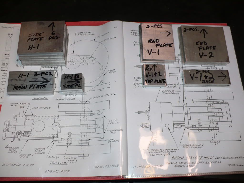
I purchased a set of plans from Hamilton's daughter, and when they arrived I knew this was going to be a great project for me. Not only are the hand drawn plans easy on my eyes, they make visualizing each part very simple. I always say that if I can visualize a part in my mind than the rest is easy. Another nice feature of this plan set is that multiple versions can be built, and the plan set include building notes and construction options for parts such as the piston and crank shaft. Below is a list of the building options that I see.

1) Horizontal water cooled 4 stroke
2) Horizontal water cooled hit-n-miss
3) F Head horizontal 4 stroke
4) F Head horizontal hit-n-miss
5) Horizontal air cooled 4 stroke
6) Horizontal air cooled hit-n-miss
7) Vertical air cooled 4 stroke
8) Vertical air cooled hit-n-miss
9) Vertical F Head 4 stroke
10) Vertical F Head hit-n-miss

You can also build customized versions of any, or all of the above!
I think you can see why I'm so happy with these plans. Not free ($13.50), but a good value for the money spent :)

Upshur Engine Works link: http://hamiltonupshur.tripod.com/

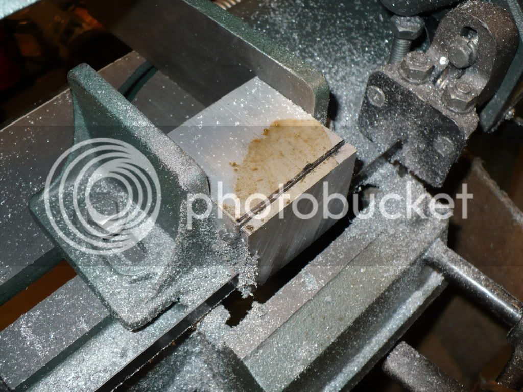
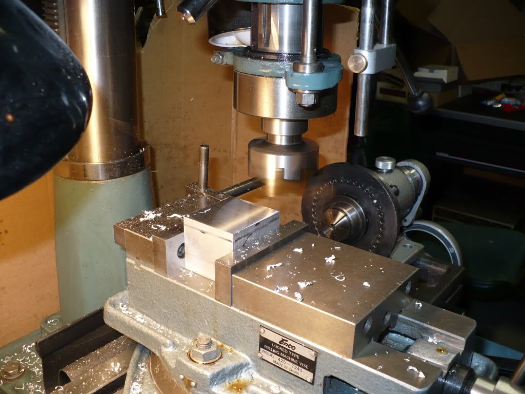
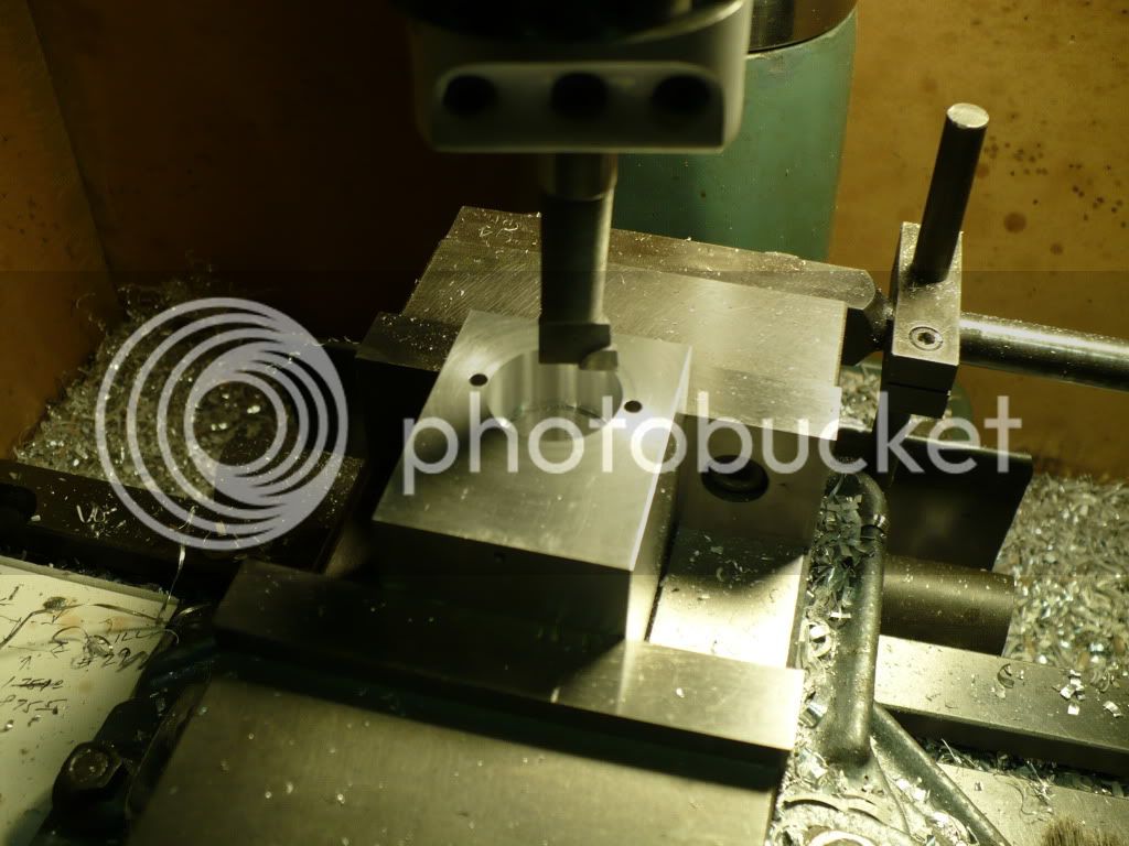
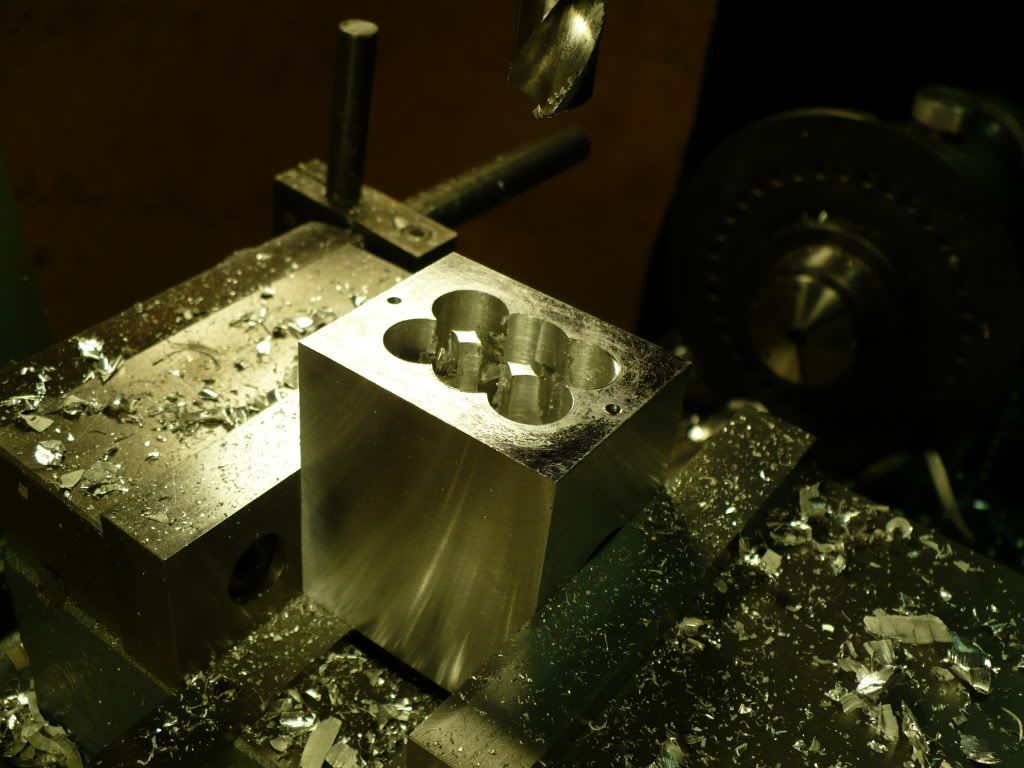
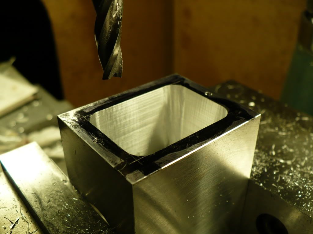
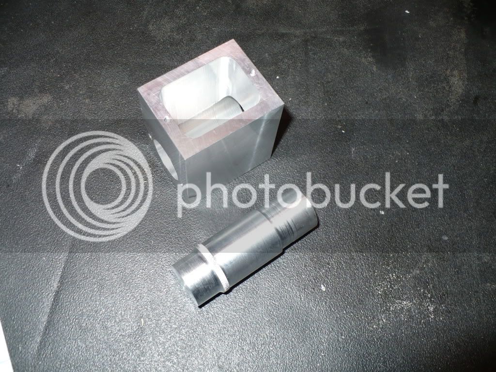
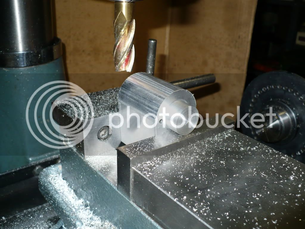
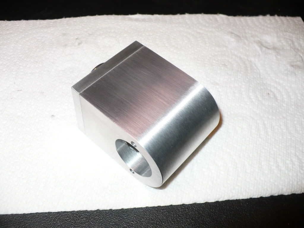
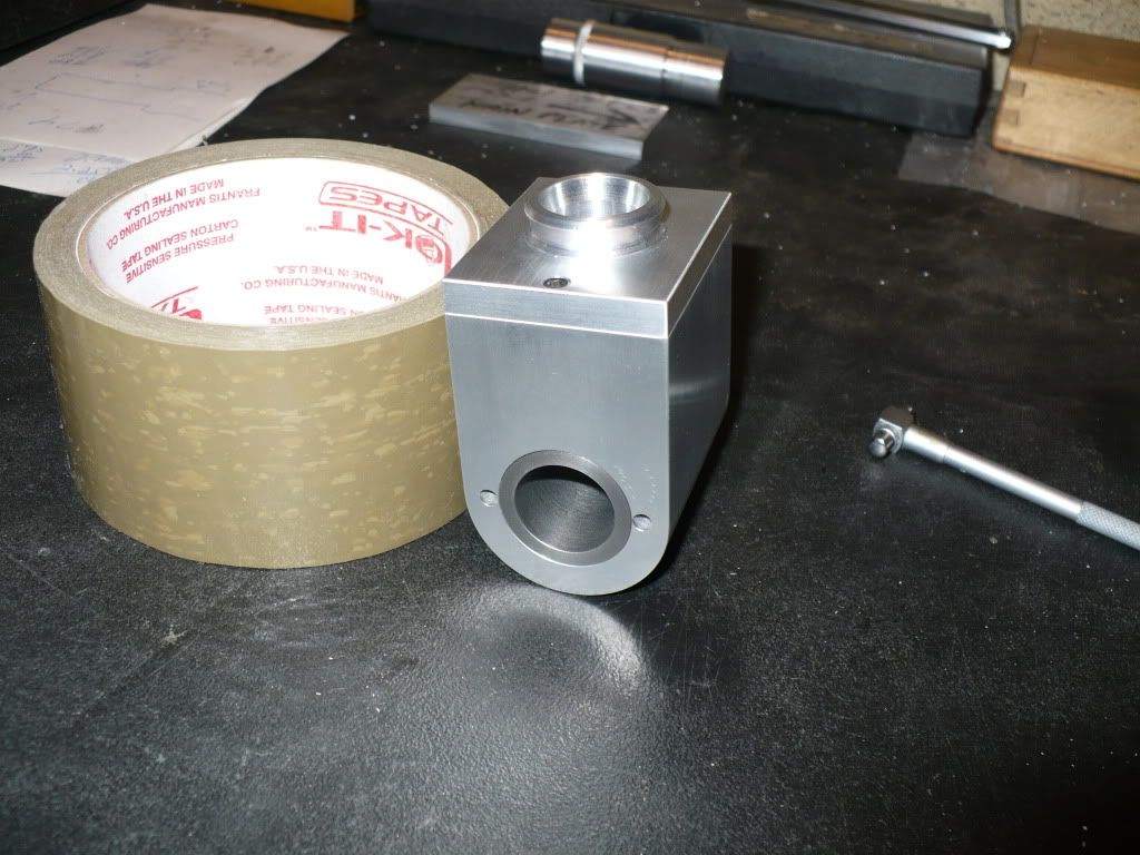
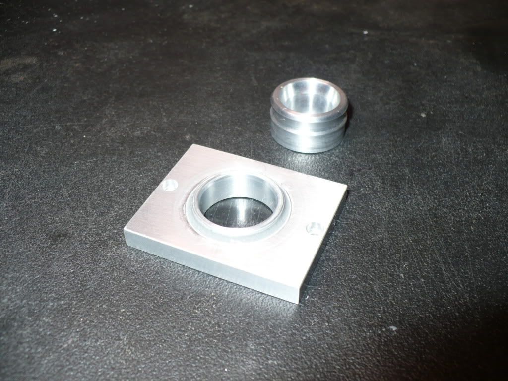
In the picture below, 20 aluminum frame plates for the 5 engines have been rough cut, milled square, and milled to final dimensions.

P1030920.jpg


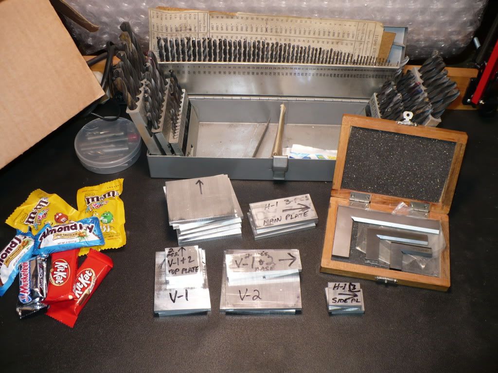
With snacks on hand, I'm ready for the final inspection of the frame plates. ("Honey" had to go back to the store and buy more candy... twice!) The stuff tastes Really good this year! ;D

P1030927.jpg


-MB


You're not wasting any time there, MB. I'll be watching with interest to see the end products.

And now, a SAFETY WARNING. Kit-kats are REALLY REALLY bad for you.

Immediately put them all in a box, and send that box to me for safe disposal. :big:

Cheers, Joe
 
joe d said:
You're not wasting any time there, MB. I'll be watching with interest to see the end products.

And now, a SAFETY WARNING. Kit-kats are REALLY REALLY bad for you.

Immediately put them all in a box, and send that box to me for safe disposal. :big:

Cheers, Joe

All boxed up and ready to ship! Rof} Rof} Rof}


Only 5 engines at a crack.... Thm:


Will be very interesting for sure. So I can get a idea of the scale, how big are the fly wheels for these engines?


Its good to have you back friend.
Matt
 
1hand said:
Only 5 engines at a crack.... Thm:


Will be very interesting for sure. So I can get a idea of the scale, how big are the fly wheels for these engines?


Its good to have you back friend.
Matt

The picture used in my first post shows a full scale line drawing on a 9" x 11" sheet. I measured 7" from the tip of the spark plug to the end of the flywheel.

The flywheels for all versions are 3-1/2" diameter.

-MB
 
MB, your projects are always informative and entertaining to follow. I'll be getting some snacks of my own and watch the show!

Chuck
 
MB, I'm looking forward to watching these guys come together.
John
 
Those are some nice plans. The art and style of a good drawing are a pleasure to use. :)
 

3) The Upshur plan set shows 2 options for a water cooled cylinder using an easy build up method of construction. I decided to make one from a solid block of 6061 aluminum. The first step was to cut an oversize blank using my 4 x 6 band saw. I lifted the saw head every 1/2" or so to add a few drops of aluminum cutting fluid. The use of a cutting fluid seems to add a lot of life to my blades.

P1030929.jpg


4) Using a fly cutter in the M/D to size and square up the cylinder blank.

P1030932.jpg


5) Two small bolt clearance holes were drilled through, and then the blank was bored for the cylinder liner. The larger of the two bores goes the full length of the blank minus a 1/4" of the smaller bore. This allows for water to get all the way around the cylinder if the cylinder diameter is turned at the smaller diameter except for a 1/4" of the larger end. To prevent rust and corrosion, a 'gas tank sloshing compound' (GTS) will be used on the interior of the water tank/hopper. I have some left over from a motorcycle project that I bought from Bill Hirsch.
http://www.hirschauto.com/products.asp?dept=4

P1030937.jpg


6) I used a 1/2" drill bit to 'hog out' the majority of the hopper opening. This went very fast and reduced the slower process of milling out to the final dimensions.

P1030942.jpg


7) It was important to set the depth of the milling just above the two through holes for the studs that will be used to mount the cylinder assembly. If I had gone too deep, it would have created a need to re-seal the mounting studs after every dis-assembly.

P1030947.jpg


8) Eight) With all the milling finished and a final inspection, my thoughts turned to a quick and simple method of creating the radius on the bottom of the water hopper. After an idea came to mind I made up a mandrel for a snug fit into the two bores of the hopper. The mandrels exposed ends were both machined to the smaller diameter.

P1030950.jpg


9) After setting the cutter height .002" above the sides, I rotated the work piece roughly 10 degrees and made the first cut (Photo is at 90 degrees.) Then it was a simple matter of 'rotate-and-repeat'. I went as quickly as I could to minimize the boredom, and ended up breaking out in a sweat due to all the cranking involved. :D

P1030957.jpg


10) After a little filing and sanding, the end result was a very acceptable radius. :)

P1030962.jpg


11) After machining down one end of a cast iron bar to fit a 1" 5-C collet using a three jaw chuck, the bar was mounted in the collet chuck for boring and machining the out side dimensions.

P1030969.jpg


12) With nothing specified in the plans, I decided that adding a 10 degree chamfer would be a good idea that would aid in the installation of a piston with iron ring(s) or O-ring(s).

P1030972.jpg


13) I added a 'trim bezel' to the opening on the hopper cover. I have mixed feelings about the way it looks, and installed it with a very light press fit just in-case I decide to eliminate the idea.

The cast iron 'cylinder liner' is a press fit, sealed up with red Loc-Tite. All that's needed to complete the assembly is to lap the bore.

P1030974.jpg


It looks like this project might take much longer than last years average build time of two weeks. ::)

-MB


Hey Rick,
It looks like you're off to a great start. Personally I like the bezel on the top of the water hopper. I know you like to add your own touches to your work. Let me know if you run into any problems. I have placed a call to the fellow about the flywheels but haven't received an answer yet.
George
 
Interesting start. I like the way you formed the curve on the hopper, although I'm not sure I have the patience to duplicate it.

Chuck
 
Hello Rick, I too like the Bezel Ring, and your method of making the radius on the hopper. It looks Great.

Kel
 
Thanks George. I already made a thinner bezel with a lower profile based on the hit-n-miss group picture you posted earlier. I like it better than the one I posted in picture #13, it seemed a little too 'beefy'. The new one is also round to stay a little closer to Hamilton's design, although I see a lot of them are square. I'll post a pic at a later date unless 'picture guy' shows up today. I'm hoping for the cast flywheels if your friend is willing to assist. This turning into an interesting project, I just hope I didn't bite off more than I can chew! ::)

-MB
 
kcmillin said:
Hello Rick, I too like the Bezel Ring, and your method of making the radius on the hopper. It looks Great.

Kel

Thanks Kel. I used the same method of incremental cutting for the first time to produce a cam profile when I built 'Chucks Single'. But instead of using the vise, I used a spindex clone. Its a better method (spindex) since there is a danger in using the vise because of the constant chucking and un-chucking. Also the increments are uniform unless you have a good eye and are lucky. Swarf can creep up under the mandrel during positioning and throw a cut off. I was careful and lucky! A real machinist would cringe at some of my barbaric methods.
Rof}

-MB
 
14) I re-designed the hopper cover bezel and made a new one. After installation I like it much better than the original one posted in picture #13. After pressing it in place I spread a thin bead of JB weld around the outer joint to blend it in with the cover. It looks much better than the bad picture that's showing an odd shadow. All I saw was the image code. Live and learn! Look out 'picture guy'! *knuppel2*

P1030976.jpg


-MB


Love the radius you put on the block. Making it look easy as usual. ;)

Matt
 
Morning Gents. The labor intensive method I used to create the radius on the bottom of the water hopper worked out well. However, there are other ways to achieve the same goal. I came up with a simple idea this morning that would allow the use of my spin fixture to eliminate the manual clamping, rotating, and re-clamping in the mills vise. This would be more accurate than the "eye ball" method I used. ::)

A slip fit mandrel could be machined up that would fit into the cylinder's bore plus an additional 3/4" to also fit into a 5-C collet. By adding two slits along its length equal to the cylinders length and at 90 degrees, the mandrel could be drilled and reamed for a tapered pin. The opposite end that would slip into the collet could be drilled for a knock out rod to meet the bottom of the tapered pin bore. I have accumulated quite a few 'Tapered Pin Reamers', and tapered pins, always wondering what they could be used for. ???

My morning visit to the "porcelain library" usually gives me plenty of time to have a cigar, let my mind wander, and come up with these ideas! :toilet:

-MB
 
14) To make two air cooled cylinders I machined a bar of 1-1/2" diameter cast iron down to 1" and machined the smaller step to .875" to fit the hole that will be bored in its supporting aluminum plate.

P1030979.jpg


15) In the same set up shown in the above picture I drilled a 1/2" hole all the way through.

P1030981.jpg


16) I set up a boring bar and machined the 750" cylinder bore.

P1030983.jpg


17) I machined the cylinders fins using a cut off blade. The correct spacing was achieved by using my dial indicator and carriage mounted travel rod.

Cutting the fins proved to be problematic to say the least! The chatter was incredible! Every thing on the lathe bench ended up on the floor. Most of the swarf also took a hike, and bolts on my tool post started to unscrew. I hung on through the entire ordeal just to finish up the job.

Distraught with this severe set back I gave George (Gbritnell) a call for advice. He immediately offered to help and came right over to see the problem first hand, and to see what needed to be done. After a demonstration of the severe chatter problem George went to work checking out the machine and asking the needed questions to arrive at a solution. Watching Georges speed and accuracy in the checks he performed was inspiring to say the least.

George suggested a reduction in my spindle speed was in order. It turned out that the speed I thought was the lowest was not. By adding the belt I removed years ago that connected the motor to the smaller clutch pulley, and switching the drive belt back to the clutch The spindle speed was reduced to 130 RPM. Another problem George pointed out was cutter height. I never knew I had to check and adjust cutter height. I use 1/2" cutters and cutter blocks that seemed to give me a good finish on Al and brass. The few times I used a boring bar I set it by eye. George set up blocks on the lathe bed and cross slide and determined the proper cutter height for my machine. After a little shimming, a test on cast iron using the cut-off tool proved that the problem was solved. I learned quite a bit that day, and trully appreciate the time that George spent to help me out.

Thanks George! Your the best! :bow: :bow: :bow: :bow:

P1030986.jpg


18) Here are the cylinder's needed for my build project of the 5 Upshur Farm Engines. From left to right. 1) Air cooled horizontal. 2) Air cooled vertical. 3) F-Head vertical. 4) F-Head horizontal. 5) Water cooled horizontal.

P1030990.jpg


19) Here I'm milling the two grooves I forgot, they cut through the fins are for the cyl and head mounting bolts.

P1030993.jpg


That's all for today folks -MB :)
 
MB where you get your cast iron from?
Looks like you get a nice finish on it.

Matt
 
1hand said:
MB where you get your cast iron from?
Looks like you get a nice finish on it.

Matt

Hi Matt. The cast iron bar came from Enco. I think its listed as Gray Iron class 40. I don't know how it compares to Dura Bar (brand?) Its interesting to machine, reminds me of Rice Crispies. ;D

http://www.dura-bar.com/

-MB
 
Back
Top