MB building Upshur Farm Engines.

Home Model Engine Machinist Forum

Help Support Home Model Engine Machinist Forum:

This site may earn a commission from merchant affiliate links, including eBay, Amazon, and others.
1hand said:
Looking good MB! I really like the fixtures you use and make. The way you use vblocks, and using your screwless vice in the bandsaw, are great ideas I've would of never thought of.

Thanks,
Matt

Thanks Matt. You know the old saying "Necessity - the mother of invention."

When I get in a jam ???, I panic and start start by digging through drawers and boxes of "who knows what this was for" stuff picked up at garage and estate sales. Seeing a tool like the screw-less vise you mentioned, or a fixture usually triggers my imagination, and a new (to me) set up is born.

-MB
 
Troutsqueezer said:
MB...slow down...you're making me look bad. *beer* :big:

Yea your right, I need to slow down. I took a day off yesterday, and half a day off today!

1/2 day progress report and picture post to follow. :big:

-MB

 
95) I took the day off yesterday at Trout's request. ;D
With today being my 'running around and errands day', I was only able to get a little done. For today's post I made the 'rocker arm'. I drilled and reamed the end of a piece of hard brass that just happened to be the correct size. Luck was on my side today.

P1040278.jpg


96) After some calculation I determined the locations for two cuts using a 1/2" ball end mill. They were the first step in a simple profile somewhat similar to whats shown on the plans.

P1040283.jpg


97) Different angle of the set-up above.

P1040285.jpg


98) I decided to round over the corners a little bit, rather than attempt a full radius. the plans show a .250 radius that looks impossible based on the part dimensions as drawn. The center-line of the end hole is .109" from the end. Maybe I missed something on the plan. ???

P1040286.jpg


99) I set up the work piece on end in the vise, and installed an R-8 slitting saw arbor in the mill. To accurately slice off the pieces the quill was lowered the same distance for each slice, using a quill mounted dial indicator.

P1040288.jpg


100) To assure a uniform thickness on the first piece, a .010 cut was taken before zeroing out the dial indicator and lowering the quill for the cut . I used a 1/16" saw, and reset the indicator for each piece. The picture below shows the first slice after it came off.

P1040292.jpg


101) After all that could be sliced came off, I sand papered off the sharp edges and checked each hole with the appropriate reamer. After a thorough scrubbing in hot soapy water the pieces were stored away until their needed on assembly day.

P1040294.jpg


That's it for today. I hope you enjoyed my 'short' progress post. :D

-MB
 
Brian Rupnow said:
Lovely work. I wish you great success when you get to the part I'm at!!!

Thanks Brian, I might need a lot of help when my turn comes! ::)

Its scary just to think about it. :D

-MB
 
102) After three attempts and eight hours, I was finally successful in making the 'lever' for my project. I found a nice piece of rolled bronze and decided it would be a good material for this part. I miss-read the plan and milled the first piece way undersized. My second attempt using another piece of the same bronze went much better. In the picture below, I'm fly cutting it down to the proper thickness.

P1040307.jpg


103) In this picture the material is being profiled with an end mill. It seemed the material was really tough to machine, even though I was using a new cutter.

P1040312.jpg


104) The workpiece was profiled on the bottom and the top. I left some material untouched on the end for clamping in the vise, when the piece will be stood up on its end.

P1040314.jpg


105) With the piece standing on end I made the first cut with a HSS slitting saw. Things went from bad to worse as the saw and workpiece started to screech and over heat. You can see the heat discoloration on both pieces. I guess this is why flood coolant systems exist. Looks like I just failed at attempt #2! scratch.gif

P1040318.jpg


106) Attempt #3! What the heck, with half a day left there is plenty of time to cut up more scrap, and turn it into smaller pieces of scrap. Rof}

This time I'm using my noodle, and picked a piece of 'machinable' brass.

P1040319.jpg


107) Profiling the underside.

P1040322.jpg


108) Profiling the top side.

P1040324.jpg


109) The work piece standing on end and being drilled for a pivot pin.

P1040329.jpg


110) I used the identical (new) saw blade and the brass is cutting like it should. I didn't need to run for cover in fear of flying shrapnel, like I did when attempting to cut the bronze! I was able to approach fearlessly, and shoot this closeup for your viewing pleasure. 8)

P1040332.jpg


111) After a little file and sand paper work the 'lever' is done. Actually I only needed one! :Doh:

P1040336.jpg


When fear strikes, run for cover! :eek:

-MB

 
They turned out very nice! Thm:
I didn't reallize that there was that much difference machining bronze verses brass!

Hopefully machining my bronze axle bearings goes ok scratch.gif
I do have a Kool Mist system that should help.

Matt
 
1hand said:
They turned out very nice! Thm:
I didn't reallize that there was that much difference machining bronze verses brass!

Hopefully machining my bronze axle bearings goes ok scratch.gif
I do have a Kool Mist system that should help.

Matt

Matt. Normally there really isn't much difference. I machined some 660 bearing bronze in the past without any problem. This stuff is a flat bar with a silver colored 'wave like' surface. The surface is also irregular and looks like it was cold rolled. Nasty stuff.

Maybe some one with more experience, will comment on the use of a coolant.

-MB
 
Brian Rupnow said:
Metal Butcher---I've made four flywheels out of bronze.---Kinda like 'Death by powder blasting".

I know what you mean. When I machine 'bearing bronze' on the lathe, the shower of the tiny hot chips feels like thousands of little needles on my skin. The stuff machines OK with a sharp (small radius) single point cutter. However, cutting off on the band saw takes much longer than any other material, including stainless and other steels. Due to the length of the band saw blades the heat dissipates and doesn't become a real problem. Using a small and thin 'slitting saw' is another story as you can see in my last progress report. Its "nasty stuff" that I won't use again, unless its called for due to its wear resistance.

-MB

 
112) For today's post I made the 'arms' for the optional hit-n-miss governor. Since its a very simple part to make the post will be a short one. I machined some scrap brass down to the outside dimensions using my fly cutter mounted in the mill/drill.

P1040338.jpg


113) I milled out a slot with a 1/2" end mill to the proper depth and shifted the table twice to open up the slot to the proper width. I didn't mill all the way to the end of the bar. The remaining material will be needed for the final steps that require the piece to be stood up on its end.

P1040340.jpg


114) The next step was milling down one side of the channel to the dimension shown on the plans.

P1040343.jpg


115) I switched the m/d over for drilling, stood the work piece on its end, squared it up, and drilled the two holes shown on the plans. In the picture below I took a light truing cut and zeroed out my DRO (quill mounted dial indicator read out).

P1040345.jpg


116) This is the fun part, slicing off pieces .0945 thick. Chop, chop, in the Butcher shop! :big:

P1040346.jpg


117) When I ran out of material to chop, the next step was to file both sides of each piece to remove the saw marks. I brought the thickness down to .0935", plus/minus .0001". Going back and forth between filing and manipulating the micrometer became tedious. So, I came up with a simple way to make this operation easier and more productive. I padded the micrometer and clamped it in my old filing vise. It was difficult to read at the zero line, so I hiked it up on a block of wood. Simply brilliant! I named my invention "The Micrometer Stand". Thm:

P1040351.jpg


118) The picture below shows the unfinished pieces, sorry I deleted the wrong picture..again. Use your imagination to picture them with the sharp edges all gone, and sanded smoother on fine paper.

P1040352.jpg


Removing the sharp edges got old very fast. So, I tried a new idea by using a 3/4" disc shaped wire brush in my rotary tool. It worked like a charm and went well. I looked through my large 3 diopter bench light to see what I was doing, and to shield me from the flying brass slivers.

Taught myself two new tricks today! woohoo1

-MB
 
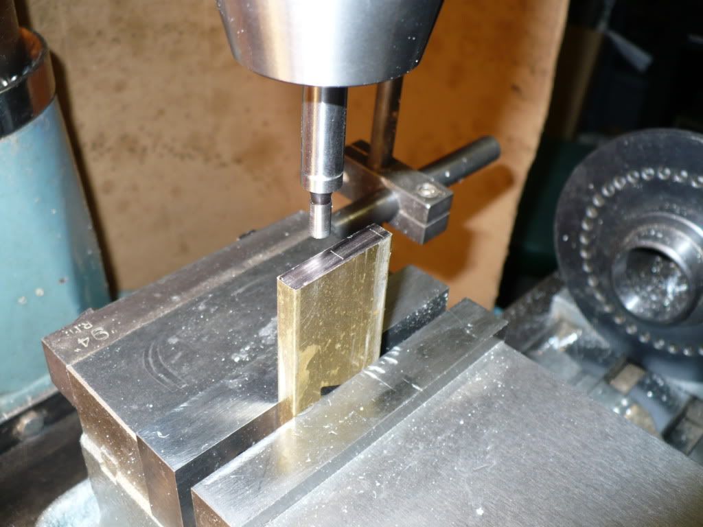
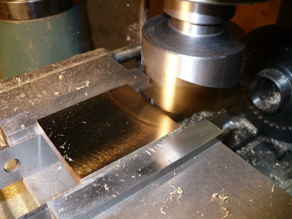
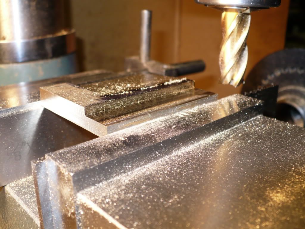
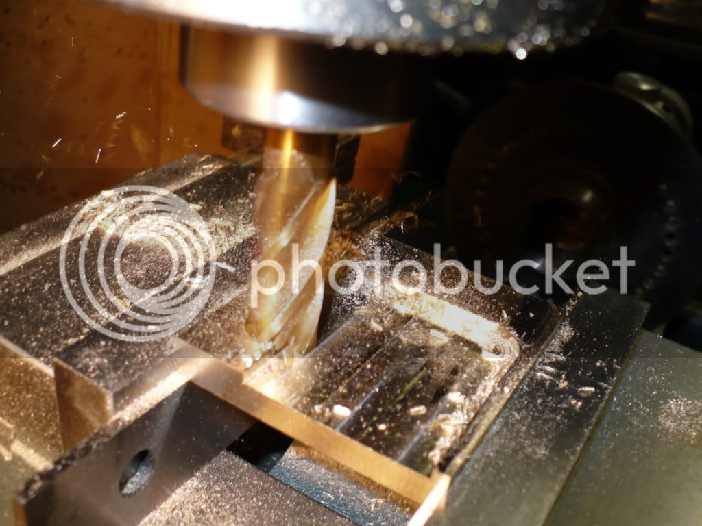
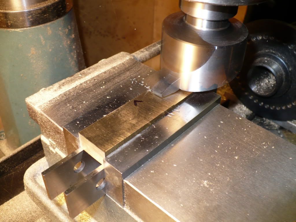
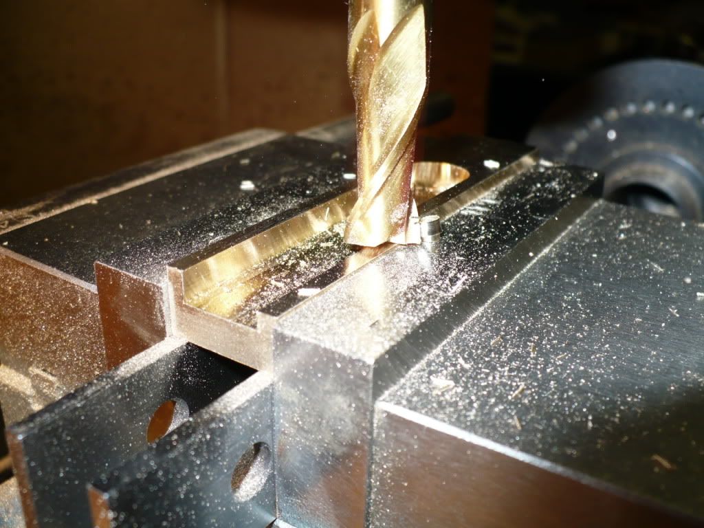
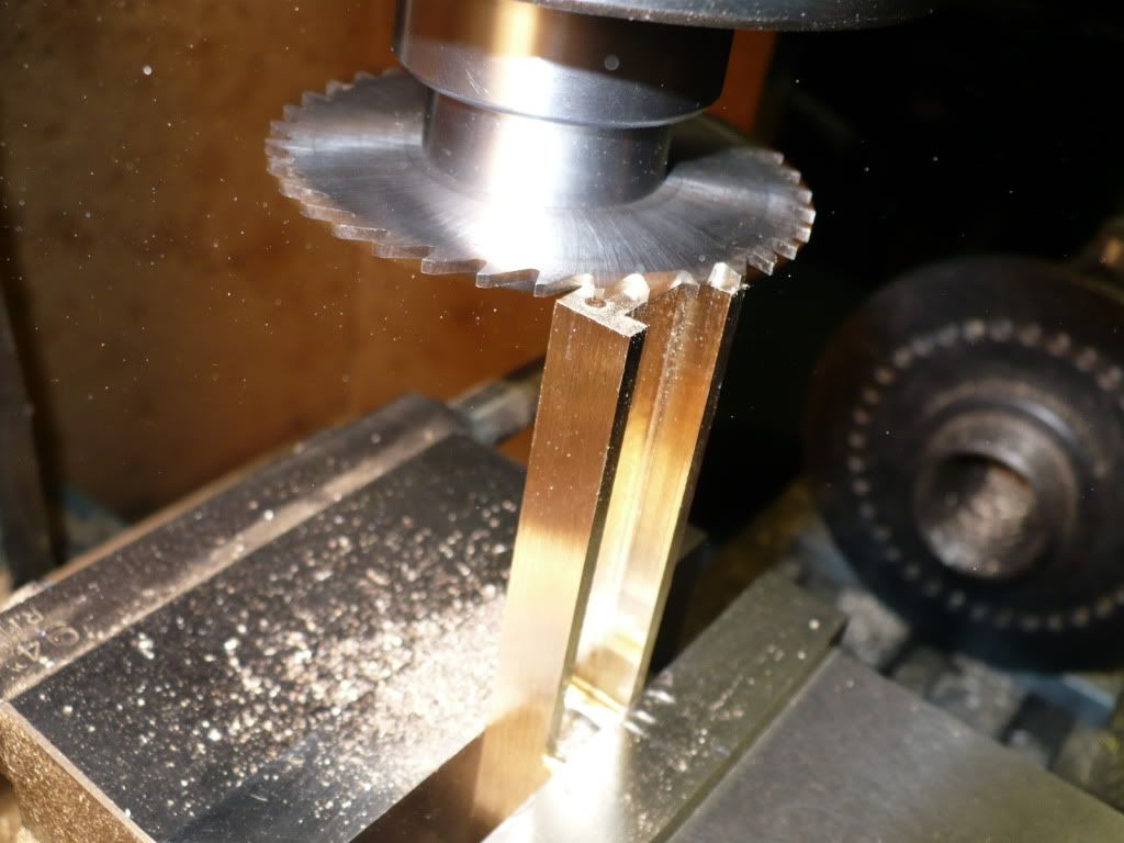
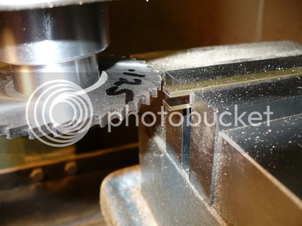
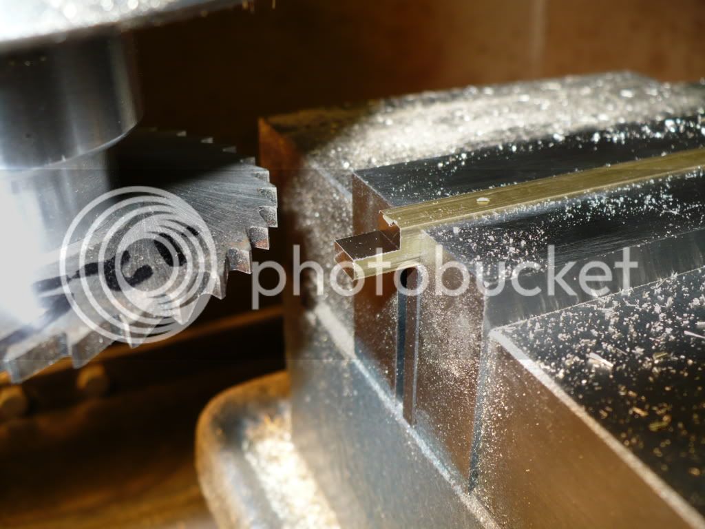
119) Today I made some small parts. I got a good start on the 'push rod clevis, 'rocker post', and 'lever pivot'. making these small and simple parts can add up to quite a few hours.I started to become fatigued and decided its best to call it a day and post the results. In the picture below some square 1/4" brass stock is getting a 1/8" slot. This was the first machining step to produce the optional 'push rod clevis'.

P1040361.jpg


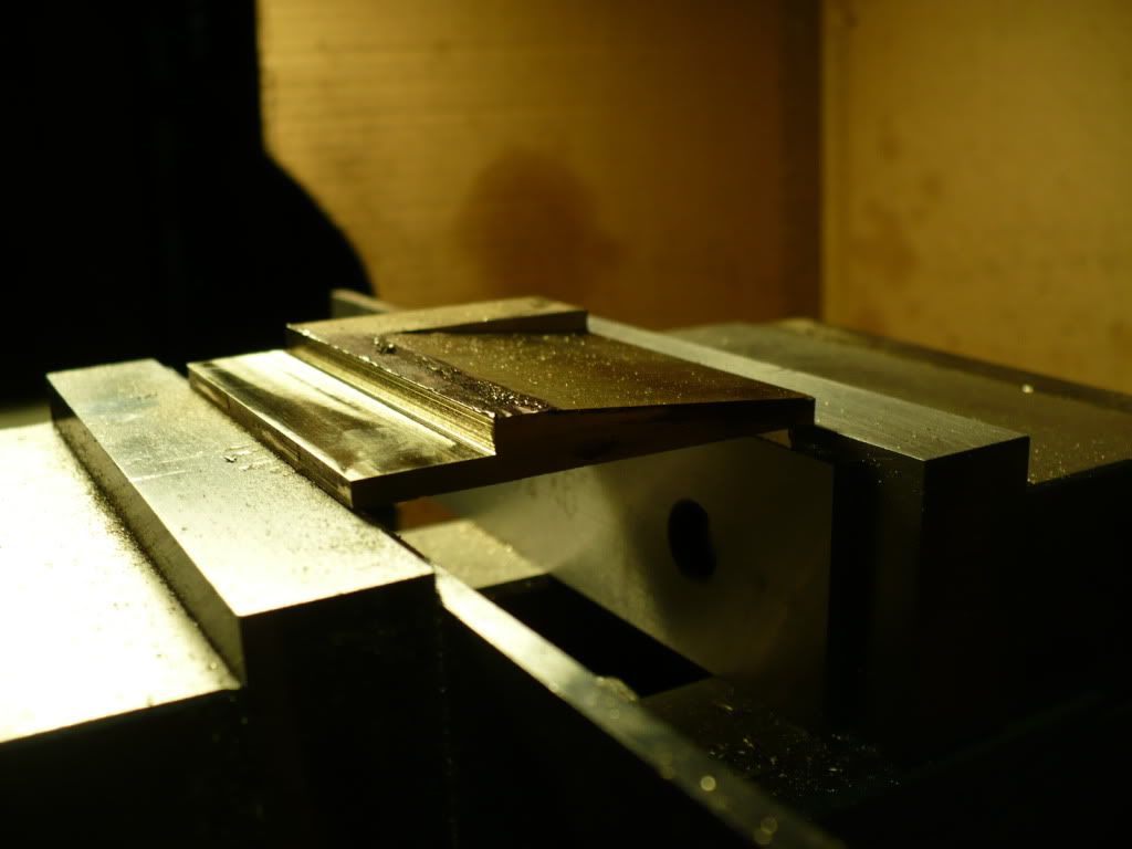
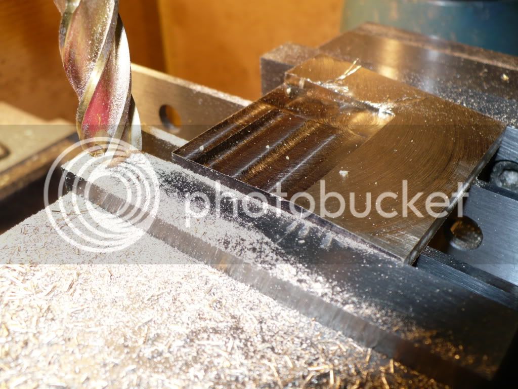
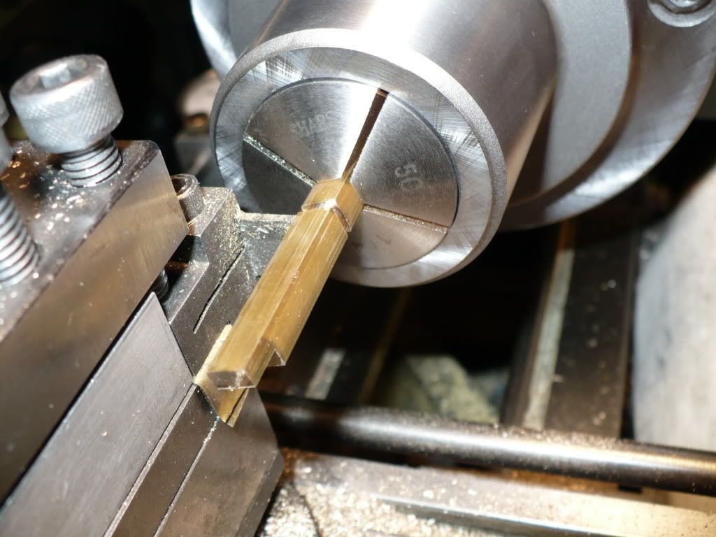
120) The second step was to cut off at the proper length. In the past I would break down the saw set-up to mill the end to length, after bands sawing the piece off. My recent purchase of a square collet simplifies the process and speeds up making multiple pieces.

P1040366.jpg


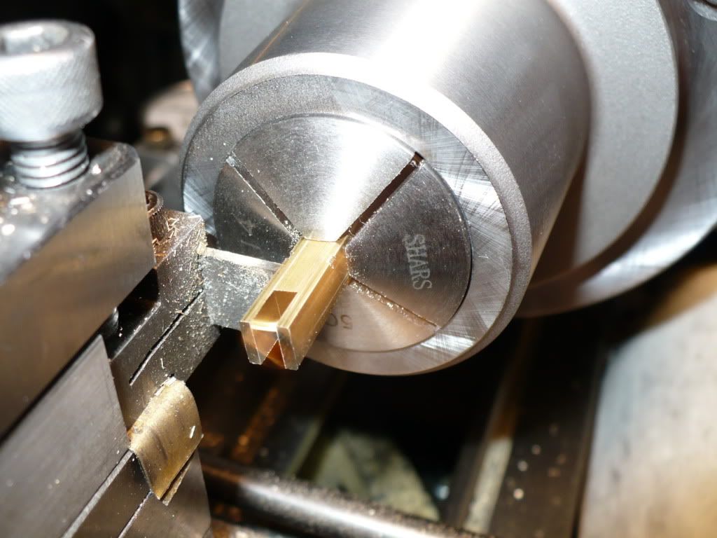
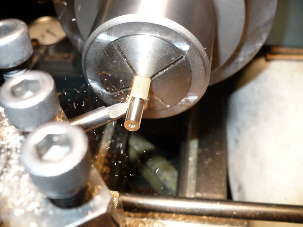
121) After parting off the 'clevis' it was reversed in the collet to produce the round detail. I got the pictures mixed up a little and deleted the one showing the spigot being turned. I think I spent too many hours going back and forth between two machines, and the fatigue is starting to show.

P1040368.jpg


122) I drilled and tapped the end of the 'clevis' 3-48. I added this to allow for adjustment to the push rod length. There is no provision for adjustment in the plans, that I can find. The push rod is 3/32" in diameter, a little thin for a 3-48 thread, but it should work.

P1040372.jpg


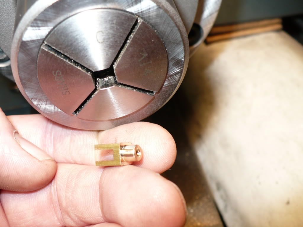
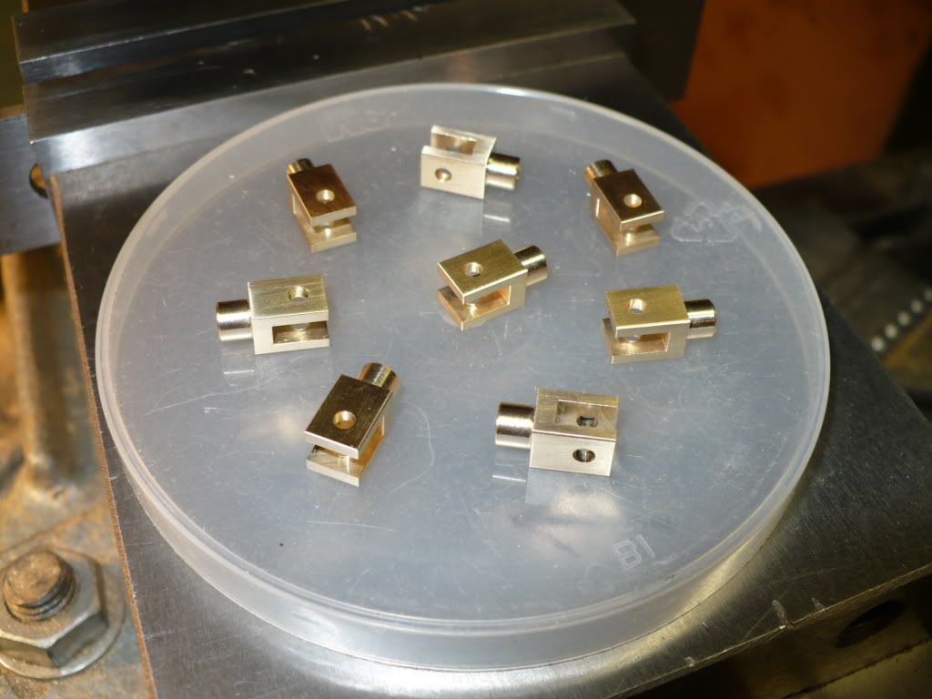
123) The 'clevis' is all but finished. I need to drill the 3/32" pivot hole as a last step, and finish up with the cosmetic's.

P1040378.jpg


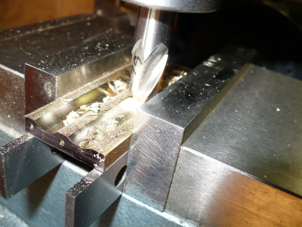
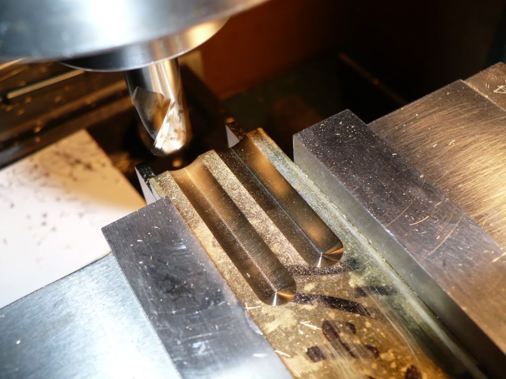
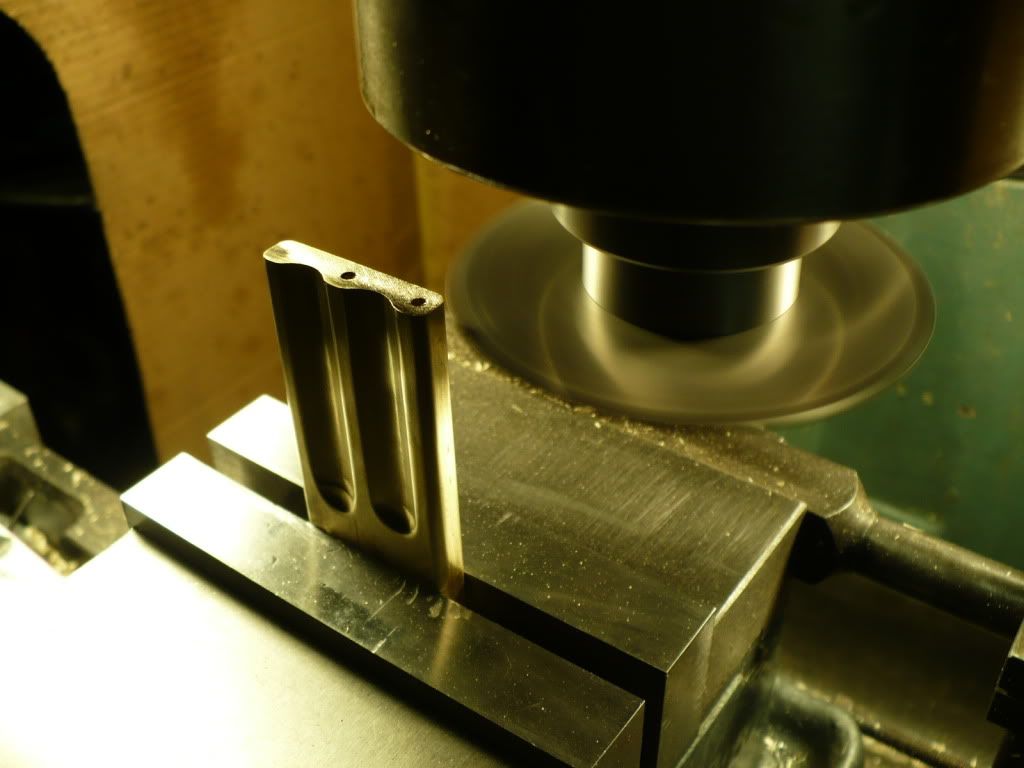
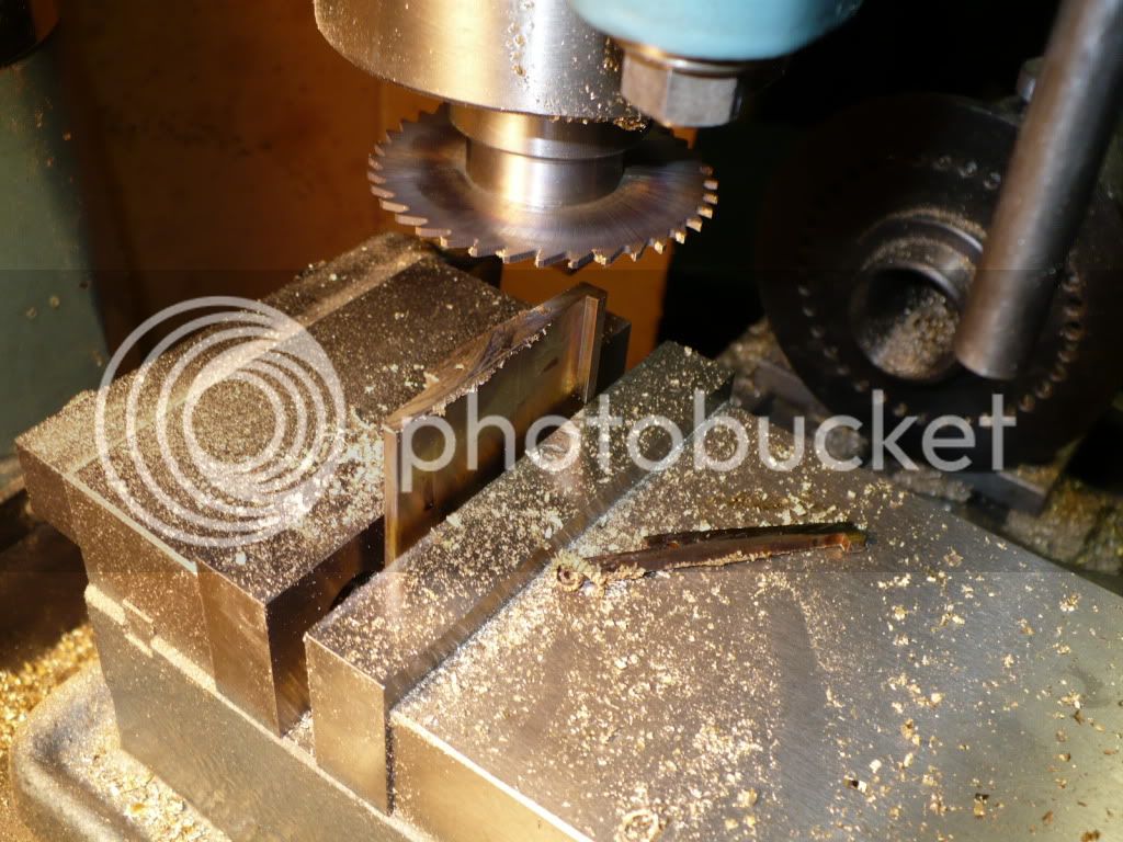
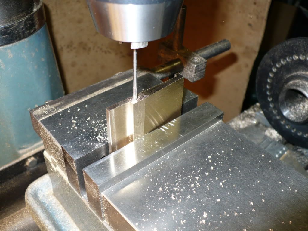
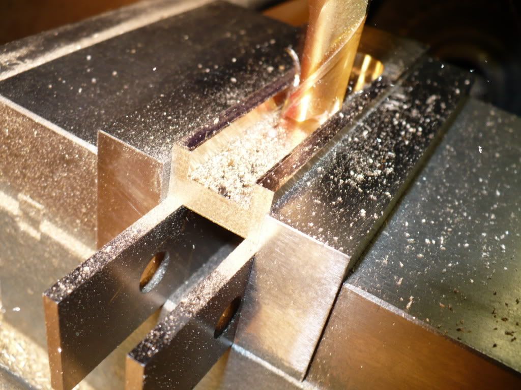
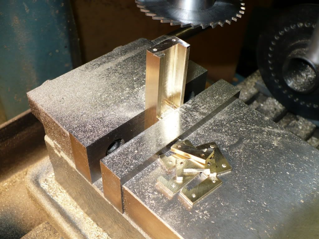
124) One half of the 'rocker post' is milled away for mounting the rocker. In the plan a 2-56" screw is used as a pivot. I will drill the post for a 3/32" steel pin, lock it in place with Loctite, and retain the 'rocker with a 3/32" E-clip. The thought of the 'rocker' pivoting on the screw's threads as shown in the plan, bothered me a bit. A partially threaded screw could also be made, it would be a good project for those that enjoy making screws. The 2-56 screws are used in other places, meaning that I would need at least 25 screws to complete the project. I like making pins.

P1040381.jpg


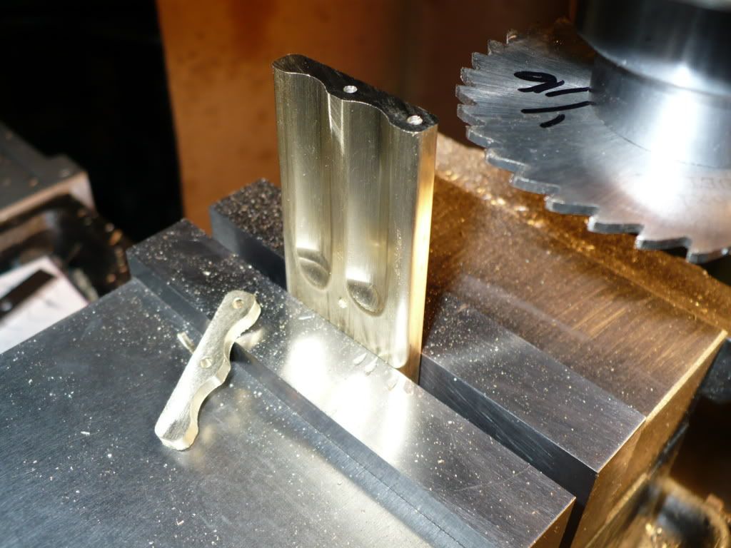
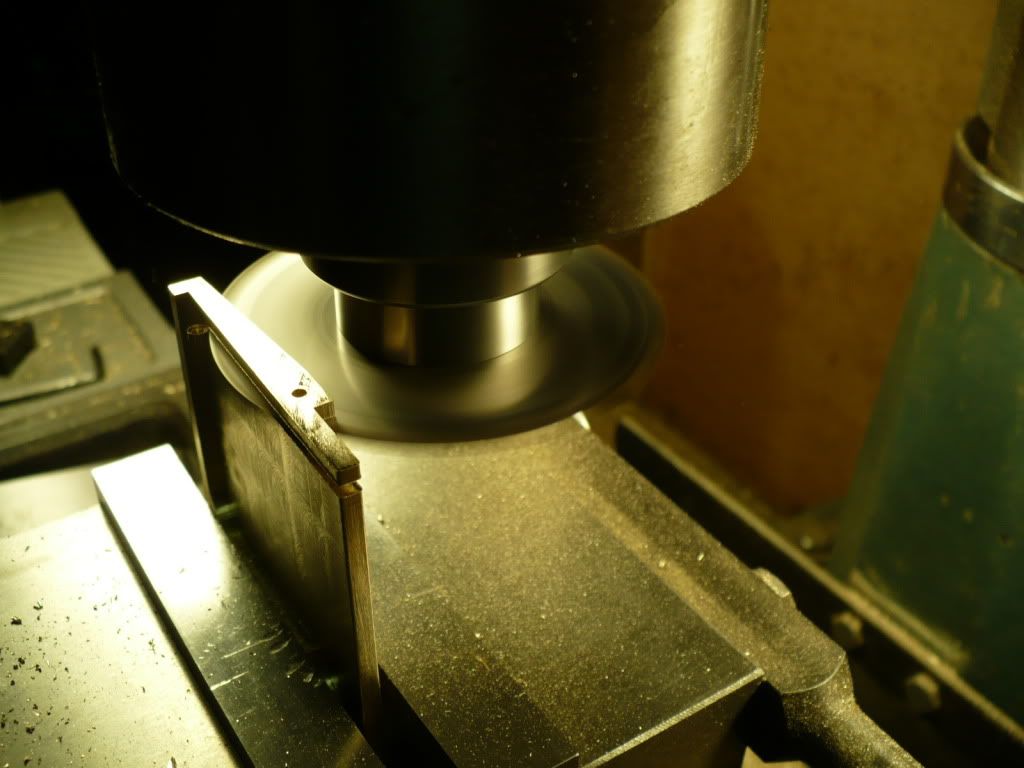
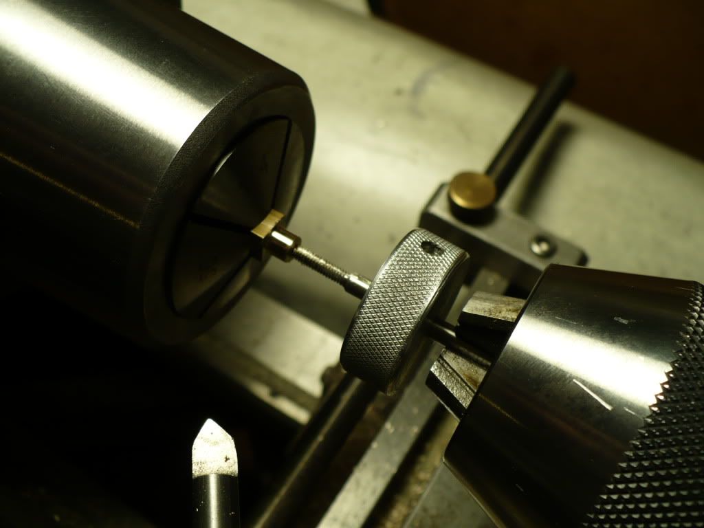
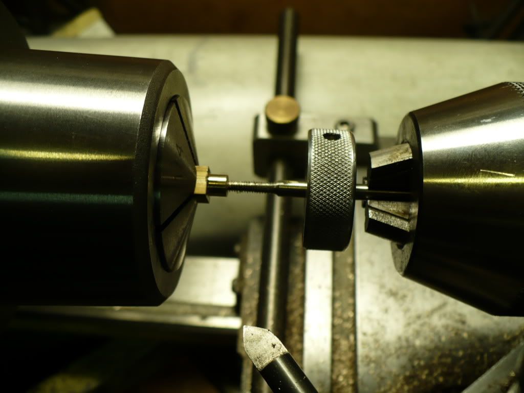
125) With the saw cut finished, the 'rocker post' was transferred to the lathe for cut-off.

P1040383.jpg


126) The rocker post was turned down to the diameter specified in the plan. I center drilled the ends for live center support. It turned out that there was no need for the tail stock support.

P1040384.jpg


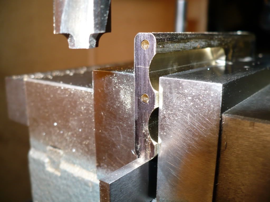
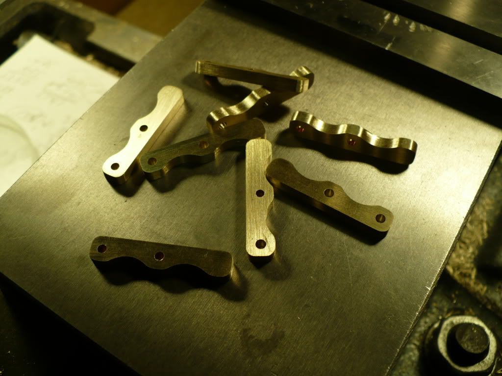
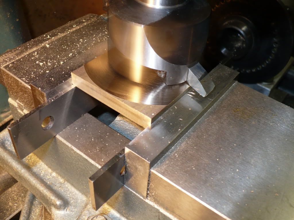
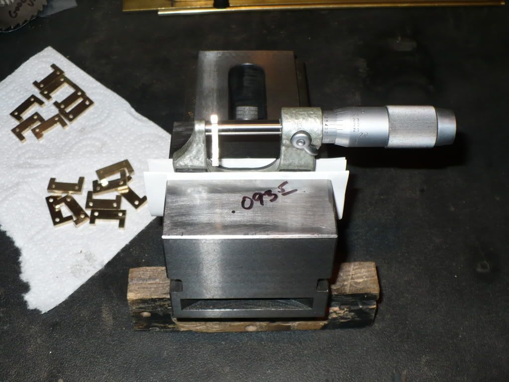
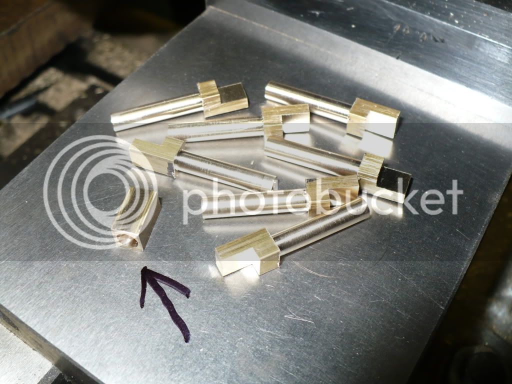
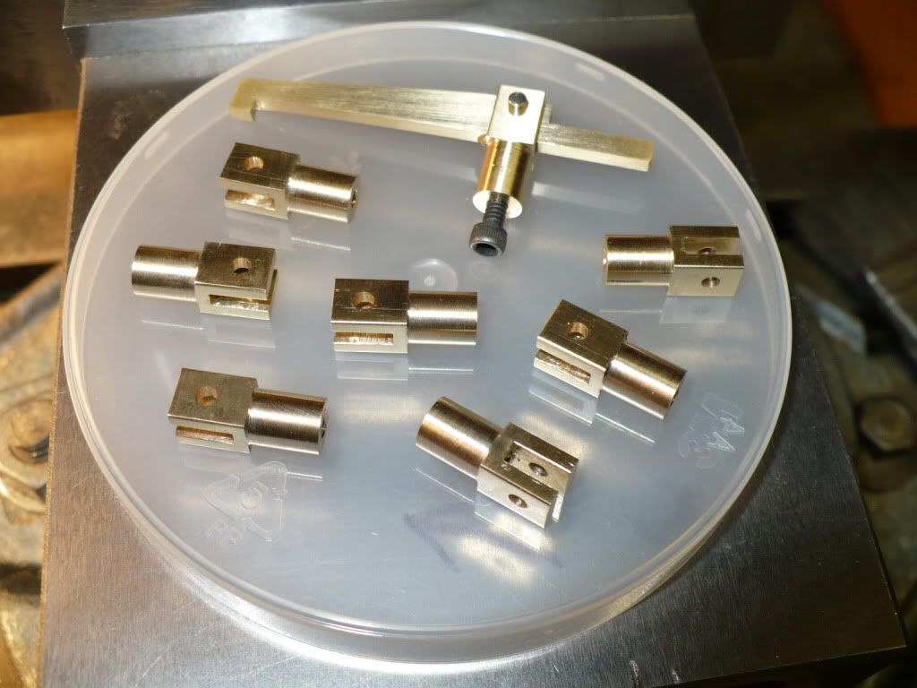
127) All that's left to finish up the 'rocker post' is to drill and ream the 3/32" pivot pin holes, and the usual clean up. The arrow is pointing to a simple fixture idea that came to mind. The bushing will fit over the spigot ends of the 'clevis' and the 'rocker post' to aid in setting them up in the m/d vise, assuring they will be perpendicular to the quill for drilling and reaming operations.

P1040389.jpg


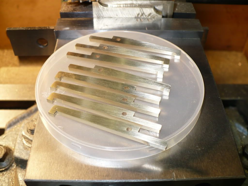
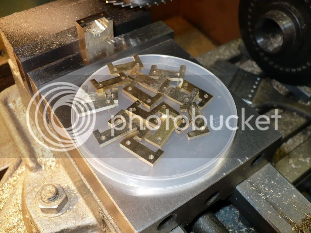
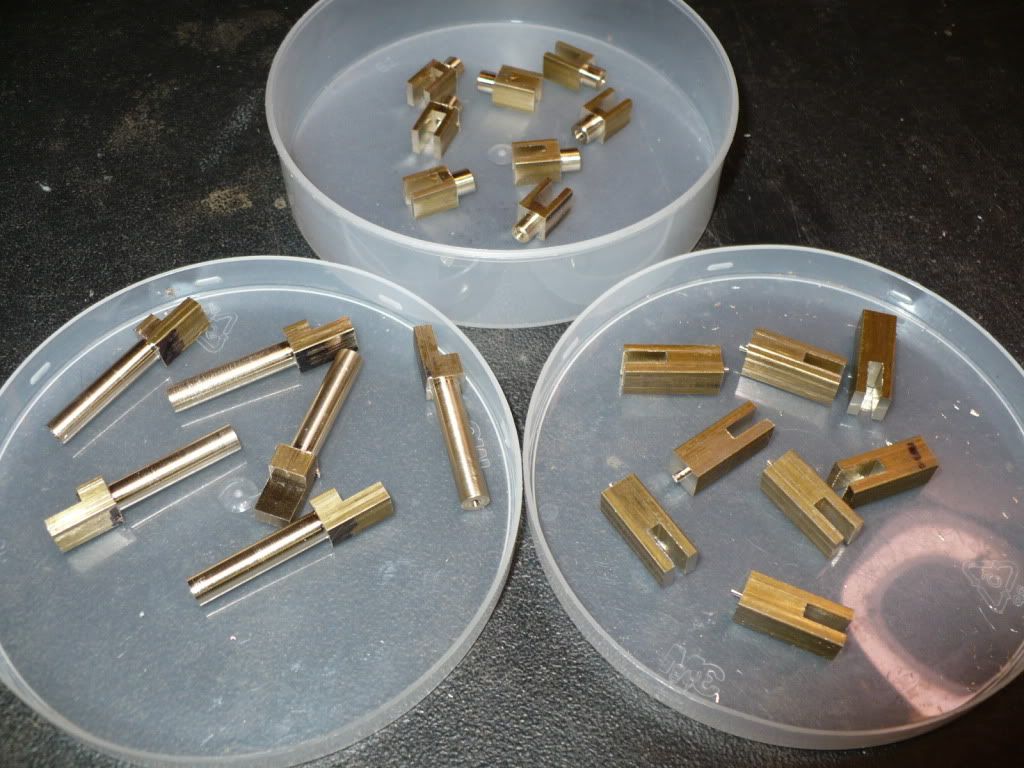
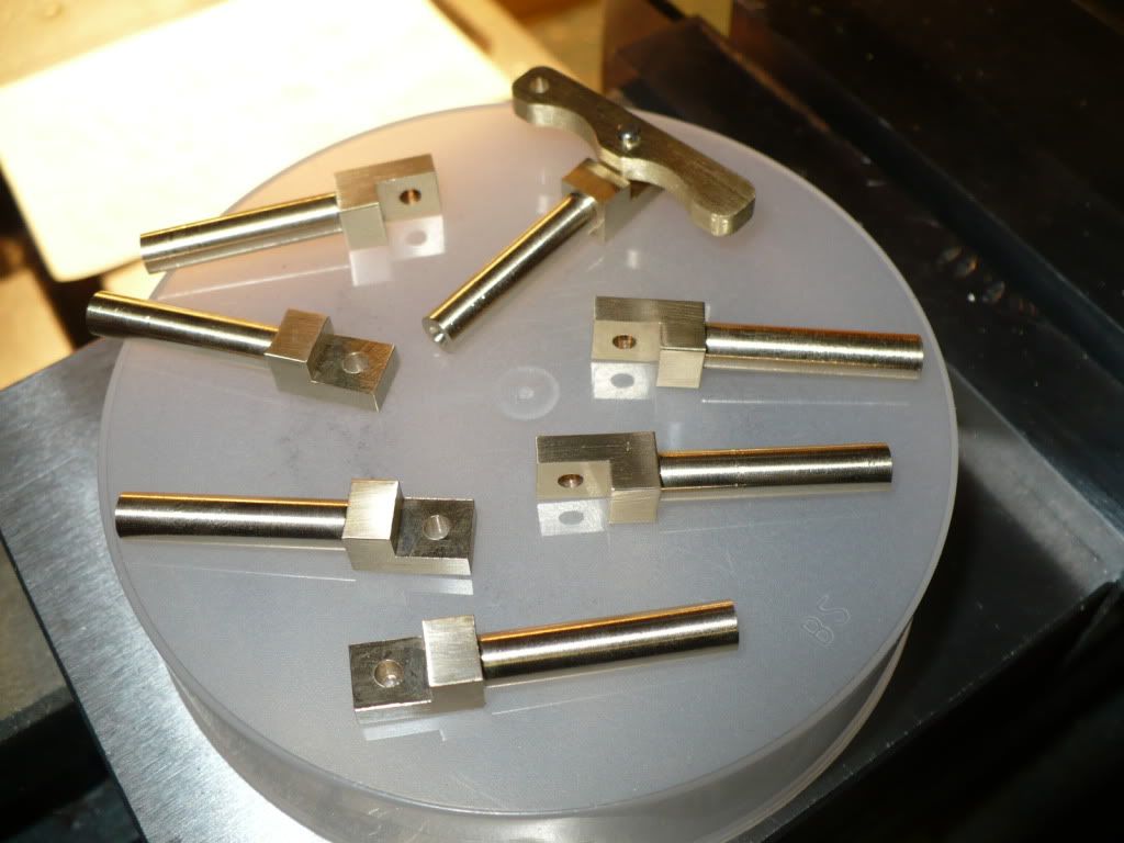
128) In the container on the lower right is the start of the 'pivots' for the 'levers'. I'll pick up were I left off tomorrow, finish up the parts I started today, and maybe take the rest of the day off by cleaning up the shop and ordering some of the supplies that are piling up on my list.

P1040392.jpg


My one day projection for these parts didn't quite work out. Oh well... its not the first time, and it won't be the last.

-MB

 
MB---Great work you are doing there!!! I've "hit the wall" for now with my project, so I'll take enjoyment from watching yours.----Brian
 
Coming along really well, Rick. A guy has to pretty much be in 'production' mode to knock off
all these parts for four engines. They all look good, too!

Dean
 
Hello

All i can say MB is you have the paitence of a saint and the hands of a sculpture and the brains to perfectionist. Super Super and just Super. I cannot wait for the next instalment.. :bow:

All the best Andy

P.S. love the use of the sharpie
 
Deanofid said:
Coming along really well, Rick. A guy has to pretty much be in 'production' mode to knock off
all these parts for four engines. They all look good, too!

Dean

Thanks Dean. Setting up for the first piece is the harder part, the rest are just time consuming repletion. Once I get a good pace going I don't want to stop. The "production mode" is the fun part that I enjoy the most. I push for the highest speed, with accuracy to avoid making scrap. I usually push too hard and the latter (scrap) starts to pile up! :rant:

I haven't seen you posting on a build thread lately, are you working on any project at the moment?

-MB
 
oshb5 said:
Hello

All i can say MB is you have the paitence of a saint and the hands of a sculpture and the brains to perfectionist. Super Super and just Super. I cannot wait for the next instalment.. :bow:

All the best Andy

P.S. love the use of the sharpie

Hi Andy, thank you for the wonderful compliment. :)

I started a bad habit of using a Sharpie to write on my workpieces , cutting tools, vises, and anything that's handy. I even wrote a stop dimension on the back of my hand recently. That was a bad idea! It didn't want to wash off for over a week! It wipes off of metal very easily using just about any solvent or cutting fluid.

-MB
 
129) I finished up the parts I started yesterday. I got an early start this morning hoping to finish up in the afternoon and take the rest of the day off from machining to do some cleaning up and relaxing. Didn't work out that way, the finish up took much longer than anticipated. The holes required 23 set-ups, with 69 tool changes! The file work, de-burring, and sanding took even longer. The good news is that I taught my self a new trick. I used a single edge razor blade to scrap off the sharp inside edges.

Below are the optional push rod clevis's. I added a tapped 3-48 thread to their holes so that the push rods could be adjustable, a feature I feel should benefit the initial set up.

P1040428.jpg


130) I cut a 3/32" pin for a test fitting of the lever pivot, and they fit like a well made glove. I havn't decided if the pins will be held in place with a little Loctite, or if I'll get fancy and groove them for E-clips.

I forgot about the drilled and tapped holes on the 8 clevis's, and the 8 lever pivot's. That's another 48 tool changes!

P1040420.jpg


131) I tried the pivot pin on the rocker arm and post and they checked out good too, with enough clearance to tilt down 45* in either direction. I was concerned if they would have enough clearance, since I changed their shape slightly to suit my idea of how they could be shaped.

P1040413.jpg


With these parts finished up, I can clean the shop tomorrow, and take care of a few other details that need my attention. Better late than never.


That's all for today folks. Thm:
-MB
 
MB,

very informative & enjoyable thread. Great information, particularly the use of fixtures. I certainly now look forward to seeing these engine operational.

Have a question for you; in picture 81 you are using a spiral cutter, which seems like a jewellers bir with a spiral cutting face. Could you please tell me what the proper name for this cutter is and your supplier source.

My normal tooling supplier has a good range of birs, but does not have the spiral version, which clearly would be desirable for mill rounding to avoid shatter or climbing (as is the case with conventional 4 face cutters) and certainly far better compared to using abrasive drums.

thank you for the input in advance

Bernard

The Model Works Australia
 
Back
Top