
You are using an out of date browser. It may not display this or other websites correctly.
You should upgrade or use an alternative browser.
You should upgrade or use an alternative browser.
MB building Upshur Farm Engines.
- Thread starter Metal Butcher
- Start date


Help Support Home Model Engine Machinist Forum:
This site may earn a commission from merchant affiliate
links, including eBay, Amazon, and others.
They're just beautiful, Rick. Very nice work!
Just one more note about HRS; When you buy it, it doesn't have to be A36, which is regular old
structural steel, and what most people think of when you say "HRS". It can still be 1018, just hot
rolled. I would give 1144 a try for your next one, though. It's perfect for things like cranks.
I have a number of prints where the crank is called out as HRS, for the reason that plagued your
first one. It's a lot of work just to have it go pretzel on you.
Keep it up. Things are looking really good! Great thread.
- Joined
- Dec 28, 2008
- Messages
- 1,731
- Reaction score
- 9
cfellows said:Beautiful work, MB. I'm inspired to try a crankshaft using your method. I always did prefer using a finished rod for the journals.
Chuck
Hi Chuck, thanks. I like using a finished rod. It makes for a nice controlled fit into the webs, and also the piston rod and crank shaft bearings. I haven't given up altogether on the idea of machining single piece crank shafts . I just think that cold rolled is not a material I'll ever use again. I used this idea to simplify the assembly, make the crank shafts accurate, and to keep the project moving forward.
Since I used a duplicate pair of inexpensive set of blocks, I'll leave the fixture alone for now. I think I could knock them apart with a hammered brass bar, and clean up the glue with a remover if I need them. If you ever try this set up, I sprayed accelerator on the plate, and spread the glue on the bottom of the blocks before setting them down gently on the ground steel plate. Prior to gluing, the ground rod was clamped tight in the blocks, on a granite inspection plate.
-MB
MB
Thanks for letting us follow along on your great build. I am learning a lot. Your descriptions are very clear.
Based on your crankshaft build I am planning to use the same method on my current beam engine build.
I will continue to follow along.
Eric
Thanks for letting us follow along on your great build. I am learning a lot. Your descriptions are very clear.
Based on your crankshaft build I am planning to use the same method on my current beam engine build.
I will continue to follow along.
Eric
- Joined
- Aug 8, 2009
- Messages
- 930
- Reaction score
- 12
You must have a generous supply of brass there MB. Can I have some? Interesting how your approach to machining the con rod is so different from mine yet we both got there, huh? Have you figured out what you are going to do for the oil cup(s)?
-Trout
-Trout
- Joined
- Dec 28, 2008
- Messages
- 1,731
- Reaction score
- 9
Troutsqueezer said:You must have a generous supply of brass there MB. Can I have some? Interesting how your approach to machining the con rod is so different from mine yet we both got there, huh? Have you figured out what you are going to do for the oil cup(s)?
-Trout
Good timing Mr.Trout! I just came up to have a smoke and checked in on the forum. "Can I have some?" Sure, stop by my shop latter today and I'll let you pick out all that you need for your Upsur build! You have to pick up brass in person you know, no illegal shipping especially out of state. The stuff causes cancer in out of state lab rats! Weak immune systems from laying around under the sun, I guess. The locals here are work hardened, and tougher than tool steel! Rof}
The way you made your con-rod using a rotary table, is probably the correct/conventional/standard method. The set up I used is the third method I have to work around the use of a ro-tab. See... lazy can be a good thing!
")
No idea's on the oil cups yet.
-MB
- Joined
- Dec 28, 2008
- Messages
- 1,731
- Reaction score
- 9
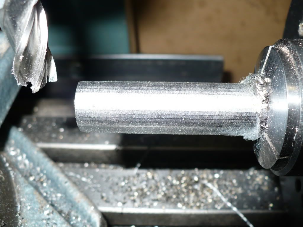
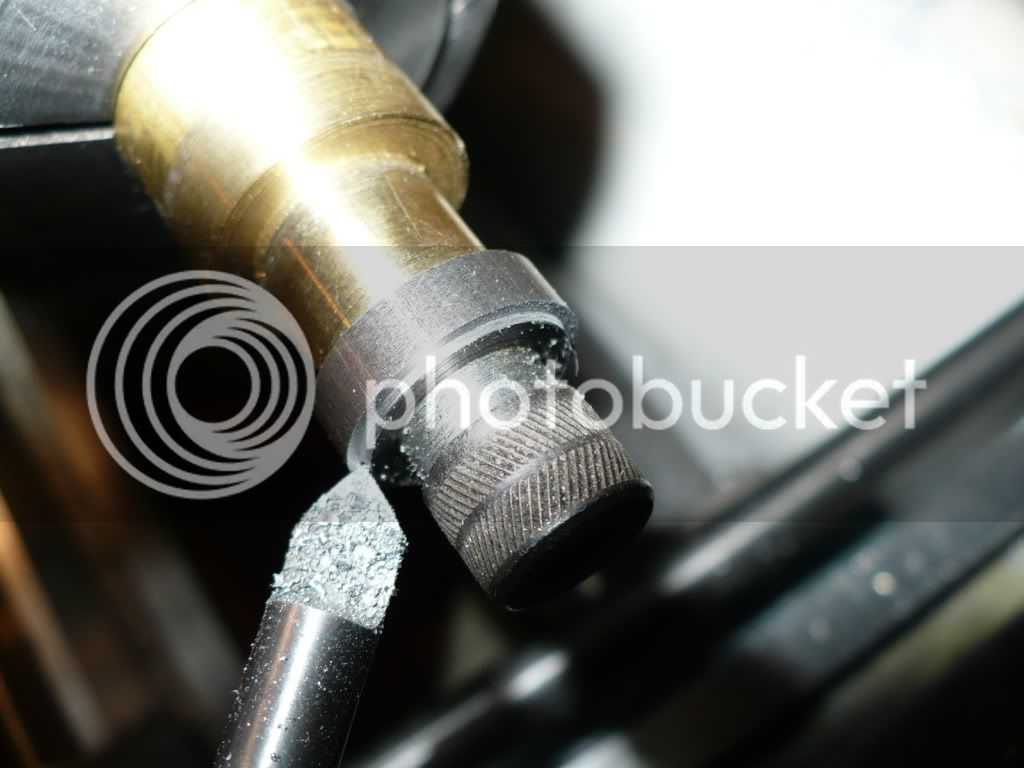
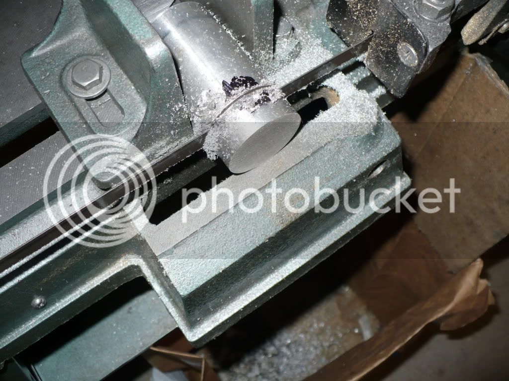
67) Today's post will show how I made the cam and cam gear carrier, and also the crank gear hub. It's a quick and simple method that has worked well for me in the past. A 3/4" Steel bar was machined down to the specified major diameter of the cam on the lathe. I profiled the blank for the cam using a spin fixture mounted on my mill. The end mill was lowered .001" at a time till it touched the work piece, and then shifted off to the end and lowered to the specified minor diameter of the cam. After the cutter was taversed back and forth to make the first cut the spin fixture was reset 10 degrees to take another cut. It took 25 cuts (0 to 24, inclusive) to match the 120 degree shown on the plans as a 1/4" remaining on the major diameter. To reduce the time needed to blend the flats created by the incremental milling, I moved the pin on the spin fixture from the #1 position up to #5. This gave me 23 cuts in-between the previous ones, cutting the increments (flats) in half. In the picture below you can see the smaller steps, created by what I call double-cutting, that will require much less blending time compared to what I've done in the past.
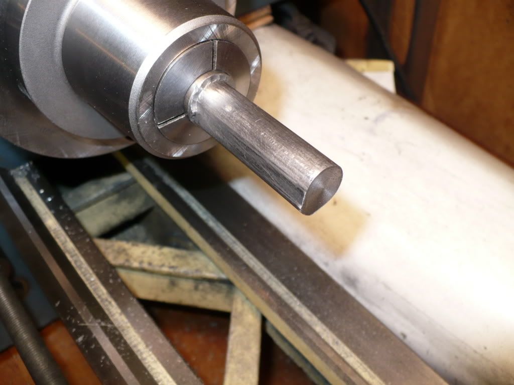
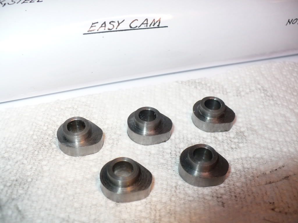
68) I transferred the 3/4" collet and stock back to the lathe to blended the cuts by hand with a smoothing file. Clamping the stock in a vise would due, its just easier on my 'back problem' to use the lathe due to the collet chucks height.
69) I went over the profiled blank very lightly and length-wise with a fine stone to see how well the filing went. The surface looked good with only a few light milling marks , so I finished up by polishing the surface shoe-shin style, using a strip of cloth backed abrasive (crocus cloth).
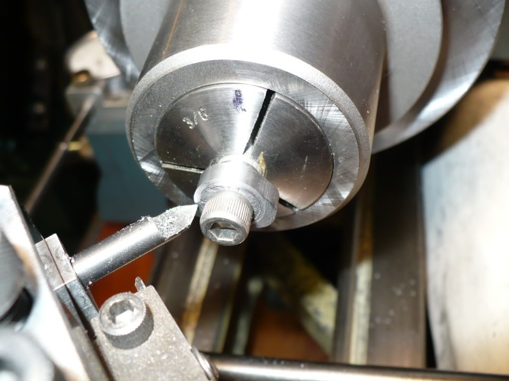
70) The next step was to carefully drill and ream a .250" hole for the cam's pivot pin. I checked the bore with the actual pivot pin material in insure a close running fit before going on to the next steps. In the event of an unacceptable bore to pivot pin fit (It can happen) the piece would need to be scraped. In the event of needing to starting over It would have saved time to do the profile milling after the bore was finished, but doing it in this final set-up assured that the gear would run concentric (important) with the bore. After the press fit step .125" wide by .375" in diameter was added for mounting the gear, the cam was parted of 5/16" wide.
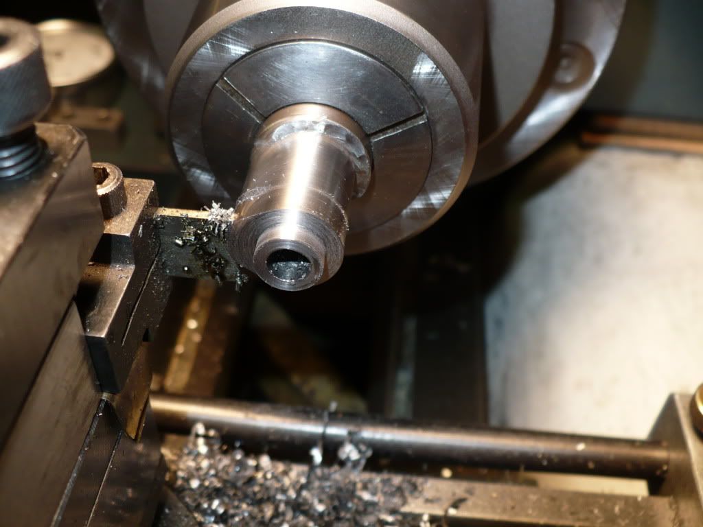
71) The method Hamilton shows ("easy cam"), is to make a fixture and turn the cams profile on the lathe. I didn't understand this method, so I made them using my self taught method. Below is a picture of the semi-finished cams. Works for me, give it a try.
72) I didn't like the idea of the entire cam profile rubbing up against the engines frame, so I bolted the cam to a simple machined-in-place fixture and machined a .010" step for the cam to ride on.
73) I purchased the gears for this project as recommended in the plans, from PIC Design, a division of RBC Bearings. Both of the gears are stainless steel, .125" wide with a .375" bore, models #J1-30 and J1-60, 30 and 60 tooth.The gears were made to order with a lead time of three weeks. These are extremely well made, and referred to as "instrument quality" by Hamilton. I'm very impressed with the quality, and will eventually get over their price. :-
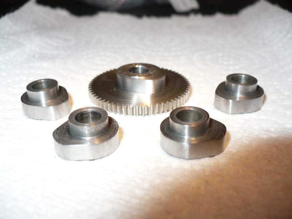
74) I machined up a bushing for the smaller crank shaft mounted gear, with the same mounting step as the larger cam gear. In the picture I'm parting it off at the same 5/16" width.
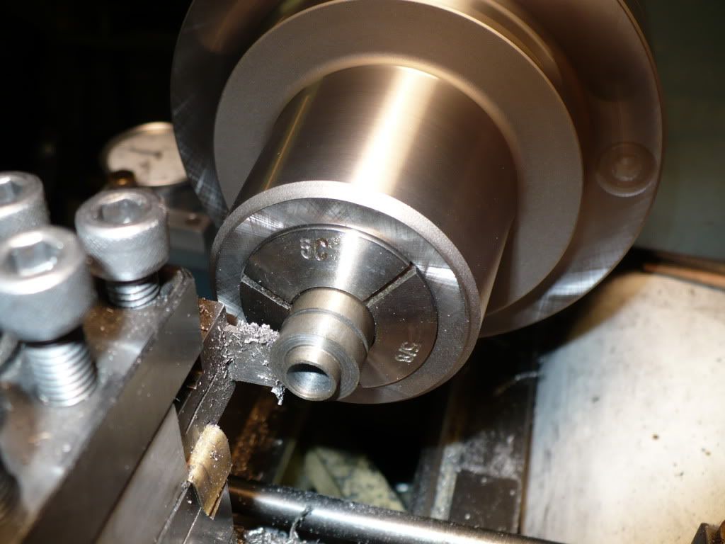
75) A .020" step was machined on the gears bushing to just below the bottom of the gears teeth. I did this as a precaution to prevent damaging the teeth on the cam gear in case one of the gears track off center, and also to eliminate the corner that might trap dirty oil or dust.
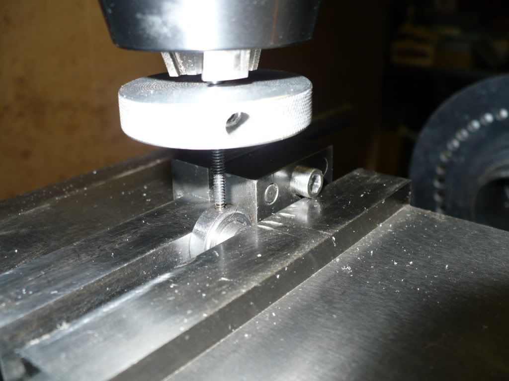
76) Nothing new here. I just wanted to show any beginners watching the set up I used to drill and tap the duplicate small gear hubs for a set screw. The first work piece was set up on a parallel, and against a vise stop. An edge finder was used to locate the center from both directions. Then simply, center drill, drill, tap, remove, and replace work piece, and repeat. I use the stationary chuck (just barely open), to guide the tap driven by two fingers on a small 'taping disc'. This eliminates tap breakage, and the need to set up each one individually.
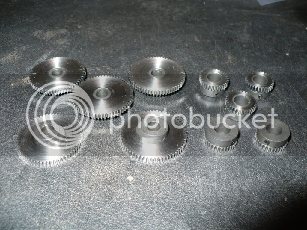
77) The gears are all finished with no place to go. This was really a simple project that took far to long. Reason being I wanted the gears to fit and mesh properly. I think I did well and do not expect any problems durring assembly.
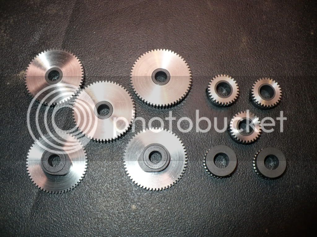
78) A last step before the photo shoot was Parkerizing the gear hubs and cam. They were made from steel that's susceptible to rusting. The parts were processed for only 5 minutes in the hot solution and turned out well.
Happy Thanksgiving every one!
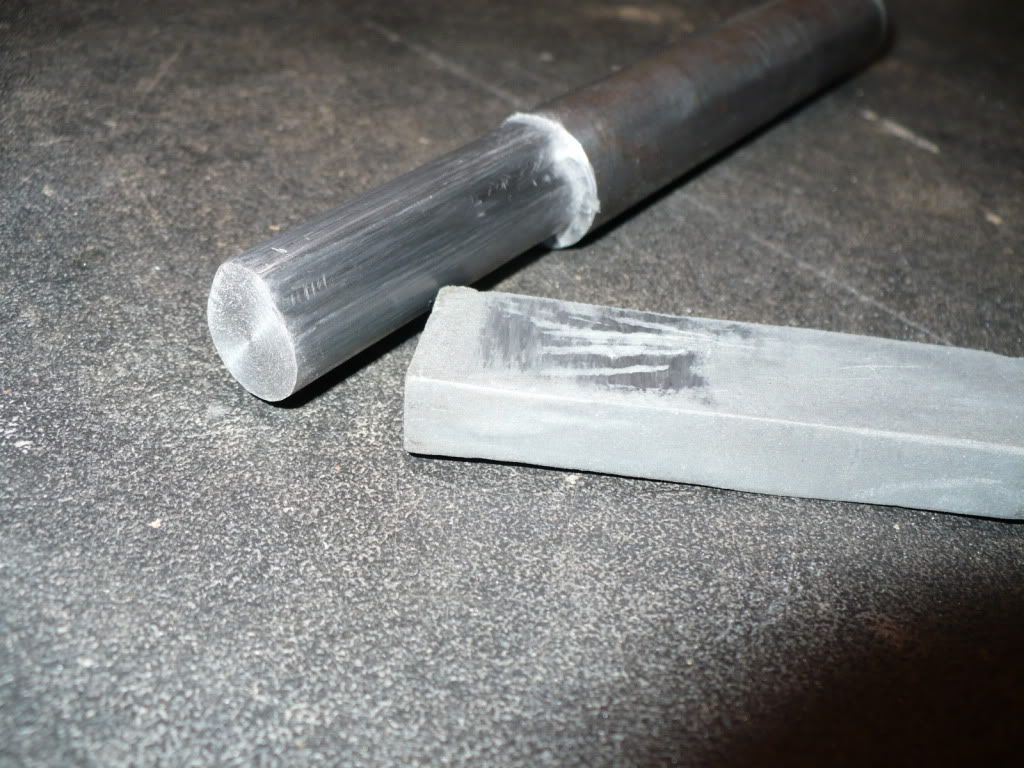
-MB
68) I transferred the 3/4" collet and stock back to the lathe to blended the cuts by hand with a smoothing file. Clamping the stock in a vise would due, its just easier on my 'back problem' to use the lathe due to the collet chucks height.
69) I went over the profiled blank very lightly and length-wise with a fine stone to see how well the filing went. The surface looked good with only a few light milling marks , so I finished up by polishing the surface shoe-shin style, using a strip of cloth backed abrasive (crocus cloth).
70) The next step was to carefully drill and ream a .250" hole for the cam's pivot pin. I checked the bore with the actual pivot pin material in insure a close running fit before going on to the next steps. In the event of an unacceptable bore to pivot pin fit (It can happen) the piece would need to be scraped. In the event of needing to starting over It would have saved time to do the profile milling after the bore was finished, but doing it in this final set-up assured that the gear would run concentric (important) with the bore. After the press fit step .125" wide by .375" in diameter was added for mounting the gear, the cam was parted of 5/16" wide.
71) The method Hamilton shows ("easy cam"), is to make a fixture and turn the cams profile on the lathe. I didn't understand this method, so I made them using my self taught method. Below is a picture of the semi-finished cams. Works for me, give it a try.
72) I didn't like the idea of the entire cam profile rubbing up against the engines frame, so I bolted the cam to a simple machined-in-place fixture and machined a .010" step for the cam to ride on.
73) I purchased the gears for this project as recommended in the plans, from PIC Design, a division of RBC Bearings. Both of the gears are stainless steel, .125" wide with a .375" bore, models #J1-30 and J1-60, 30 and 60 tooth.The gears were made to order with a lead time of three weeks. These are extremely well made, and referred to as "instrument quality" by Hamilton. I'm very impressed with the quality, and will eventually get over their price. :-
74) I machined up a bushing for the smaller crank shaft mounted gear, with the same mounting step as the larger cam gear. In the picture I'm parting it off at the same 5/16" width.
75) A .020" step was machined on the gears bushing to just below the bottom of the gears teeth. I did this as a precaution to prevent damaging the teeth on the cam gear in case one of the gears track off center, and also to eliminate the corner that might trap dirty oil or dust.
76) Nothing new here. I just wanted to show any beginners watching the set up I used to drill and tap the duplicate small gear hubs for a set screw. The first work piece was set up on a parallel, and against a vise stop. An edge finder was used to locate the center from both directions. Then simply, center drill, drill, tap, remove, and replace work piece, and repeat. I use the stationary chuck (just barely open), to guide the tap driven by two fingers on a small 'taping disc'. This eliminates tap breakage, and the need to set up each one individually.
77) The gears are all finished with no place to go. This was really a simple project that took far to long. Reason being I wanted the gears to fit and mesh properly. I think I did well and do not expect any problems durring assembly.
78) A last step before the photo shoot was Parkerizing the gear hubs and cam. They were made from steel that's susceptible to rusting. The parts were processed for only 5 minutes in the hot solution and turned out well.
Happy Thanksgiving every one!
-MB
- Joined
- Dec 28, 2008
- Messages
- 1,731
- Reaction score
- 9
Deanofid said:Nice work on those cams! Do you mind telling how much the gears ran you?
Happy Thanksgiving to you and Honey, Rick.
Dean
Hi Dean. Thanks, and the same to you. The 'bird' is making me nod off in front of the computer.
You need to either sit down, or cover your mouth so I don't see you laughing! :big:
$106 + $6 shipping. About $22 a set.
I'm trying to forget. :'(
-MB
Hi this is a very interesting build. I have a few questions first want is parkinzing, second i noticed that you use round tools for your lathe is there a reason for this or just that is what you like, are they easier to grind?
- Joined
- Dec 28, 2008
- Messages
- 1,731
- Reaction score
- 9
bronson said:Hi this is a very interesting build. I have a few questions first want is parkinzing, second i noticed that you use round tools for your lathe is there a reason for this or just that is what you like, are they easier to grind?
Hi bronson, thanks, I'm glad your taking interest in my build. If its not too difficult or too easy, perhaps you'll consider building one yourself.
I bought over 100 hss and carbide round tool bits in various diameters and ground shapes, ranging from 1/8" to 5/16". The reason I use them is that for $5 I couldn't pass them up. They are very easy to re-sharpen due to their sizes and shapes.
Parkerizing is a chemical treatment (manganese phosphate) that converts the surface of the steel giving it a satin gray or black color. It used mainly as a good rust preventative treatment that works well on tool, firearms, and other machined parts. I like its non-glare looks and the way it holds oil to protect parts from rusting.
http://en.wikipedia.org/wiki/Parkerizing
-MB
- Joined
- Dec 28, 2008
- Messages
- 1,731
- Reaction score
- 9
cfellows said:Actually, MB, $22 a set isn't outrageous. It's a little on the high side, but sounds like you got just what you needed, so that price isn't so bad.
Chuck
Yea your right Chuck, The price is in line with all the other sources. They are exactly what I needed, and also top quality. I need to stop whining and get over their cost.
What we need is a Little ol' Gear Maker with nothing better to do, to supply us with low cost gears for our projects, yea right...dream on! :
-MB
- Joined
- Dec 28, 2008
- Messages
- 1,731
- Reaction score
- 9
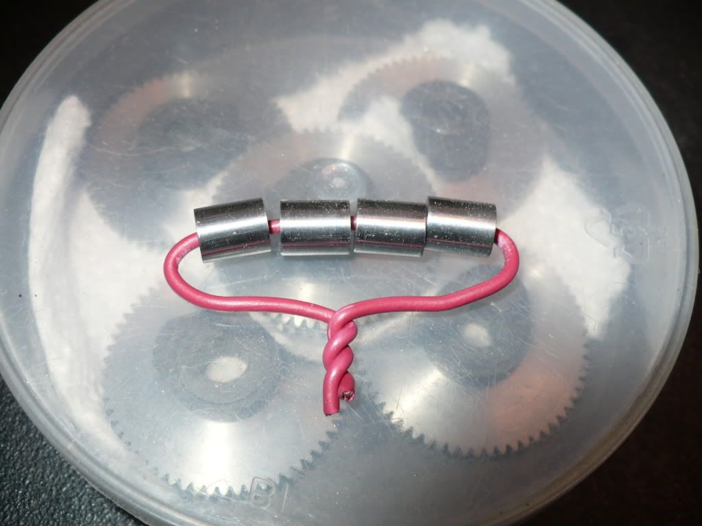
79) I made the 'cam gear sleeve's from steel. I made only 4 of them, since at least one engine will be built as a hit-n-miss version, and that requires a combination bushing with a 'pivot' for the 'lever' that engages with the governor 'spool'.
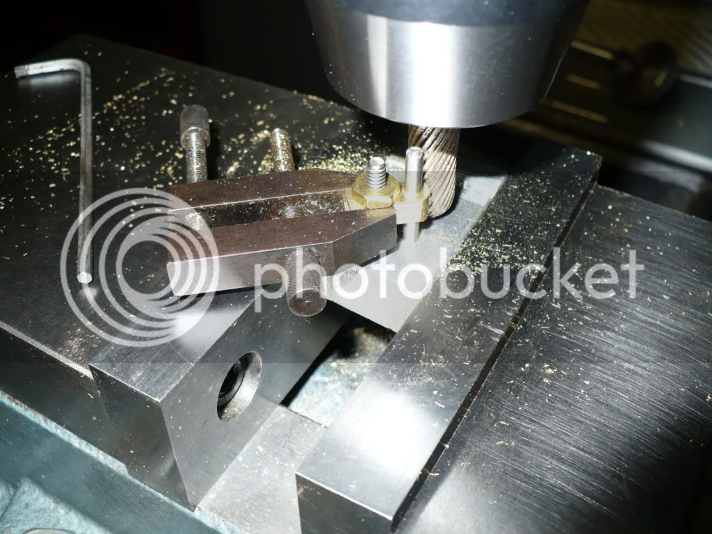
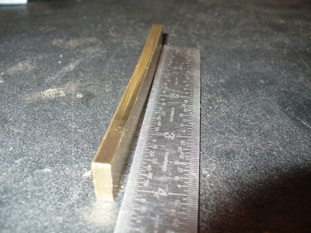
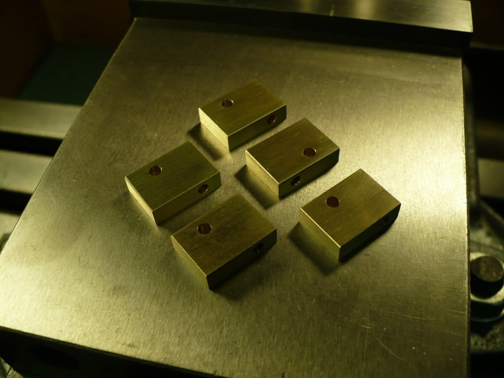
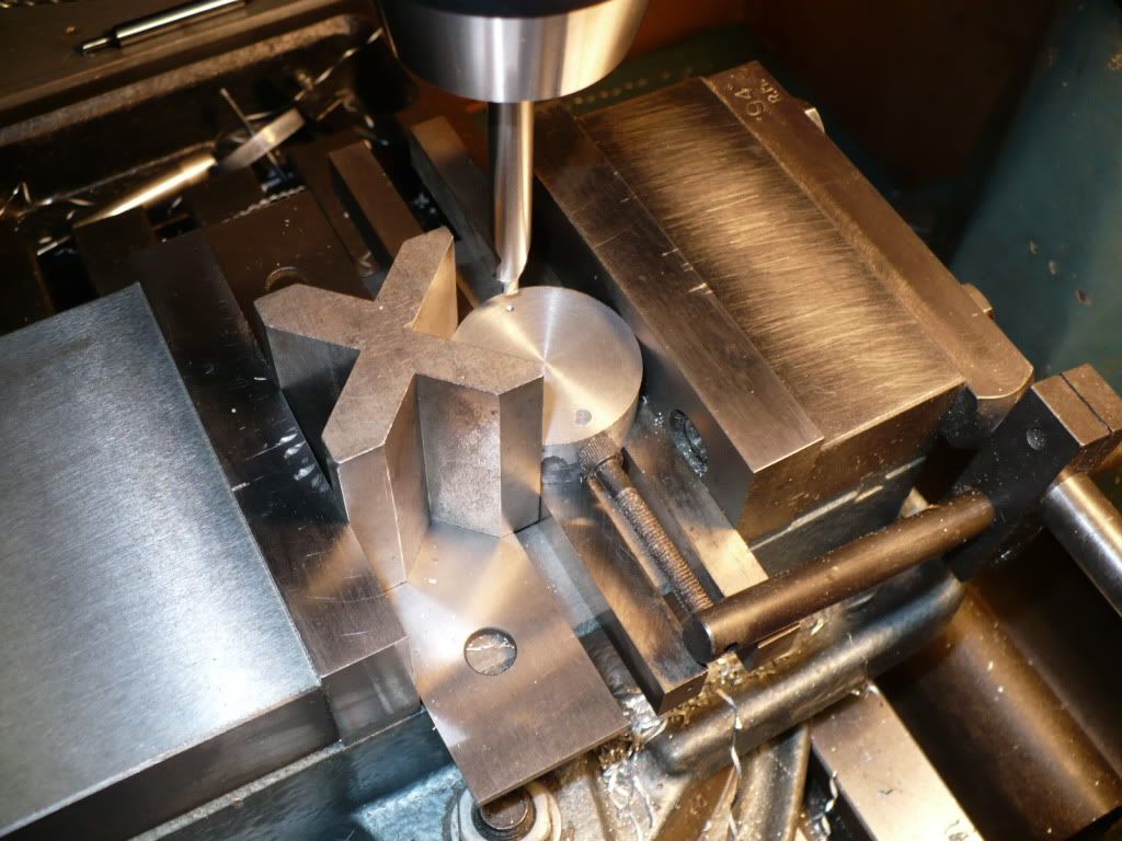
80) The 'upper push rod guide's' were simple rectangles cut from brass sheet and drilled. I stacked, pinned, and bolted them together to profile their ends with one set up using the method shown below. They were too short for hand held profiling in the mill, so I clamped on to them with a 1-1/2" machinists clamp. this was a better set up, that kept my fingers out of harms way.
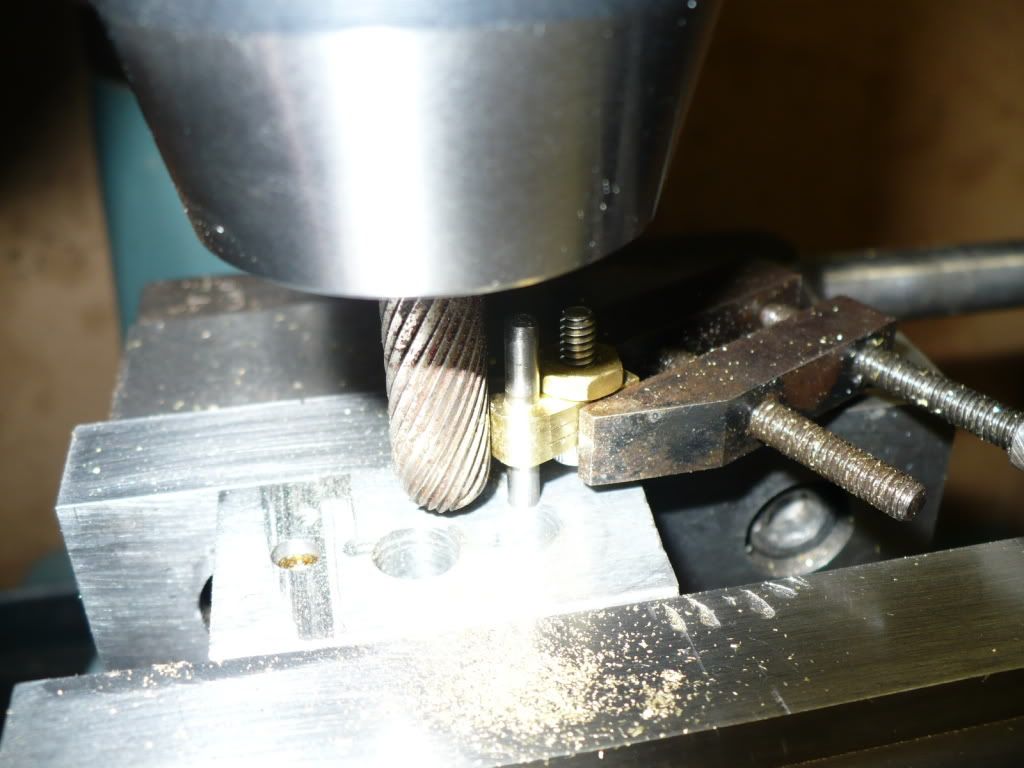
81) A picture at a differant angle of the profile milling set up I used.
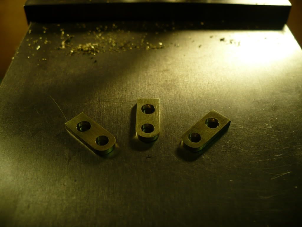
82) After a little file and sand paper work their finished. I added a small pressed in bushing on the profiled end to add more surface for the push rod to ride on. I accidentally deleted the picture showing the installed bushings.
83) Now here's a picture worth a thousand words, (curse words that is!). I needed stock 3/16" thick for the 'lower push rod guide's. Simple enough, I'll just mill down some 1/4" x 1/2" stock on hand. As soon as I released the vise's grip a chill went up my back. The brass stock sprung do to built in stress created when the stock was rolled to thickness at the mill that made it. After a lot of hammering and plenty of choice words I straitened the piece enough to where it could be salvaged and used.
84) After a little break to calm my rattled nerves, I went back down to the shop. I milled the pieces to size, drilled the appropriate holes, and finished up with a file and sand paper. They turned out as well as could be expected under normal circumstances.
Its a good thing that my project wasn't being documented with a real time 'shop cam', or I would have been booted off the forum today for sure! Rof}
-MB
80) The 'upper push rod guide's' were simple rectangles cut from brass sheet and drilled. I stacked, pinned, and bolted them together to profile their ends with one set up using the method shown below. They were too short for hand held profiling in the mill, so I clamped on to them with a 1-1/2" machinists clamp. this was a better set up, that kept my fingers out of harms way.
81) A picture at a differant angle of the profile milling set up I used.
82) After a little file and sand paper work their finished. I added a small pressed in bushing on the profiled end to add more surface for the push rod to ride on. I accidentally deleted the picture showing the installed bushings.
83) Now here's a picture worth a thousand words, (curse words that is!). I needed stock 3/16" thick for the 'lower push rod guide's. Simple enough, I'll just mill down some 1/4" x 1/2" stock on hand. As soon as I released the vise's grip a chill went up my back. The brass stock sprung do to built in stress created when the stock was rolled to thickness at the mill that made it. After a lot of hammering and plenty of choice words I straitened the piece enough to where it could be salvaged and used.
84) After a little break to calm my rattled nerves, I went back down to the shop. I milled the pieces to size, drilled the appropriate holes, and finished up with a file and sand paper. They turned out as well as could be expected under normal circumstances.
Its a good thing that my project wasn't being documented with a real time 'shop cam', or I would have been booted off the forum today for sure! Rof}
-MB
- Joined
- Dec 28, 2008
- Messages
- 1,731
- Reaction score
- 9
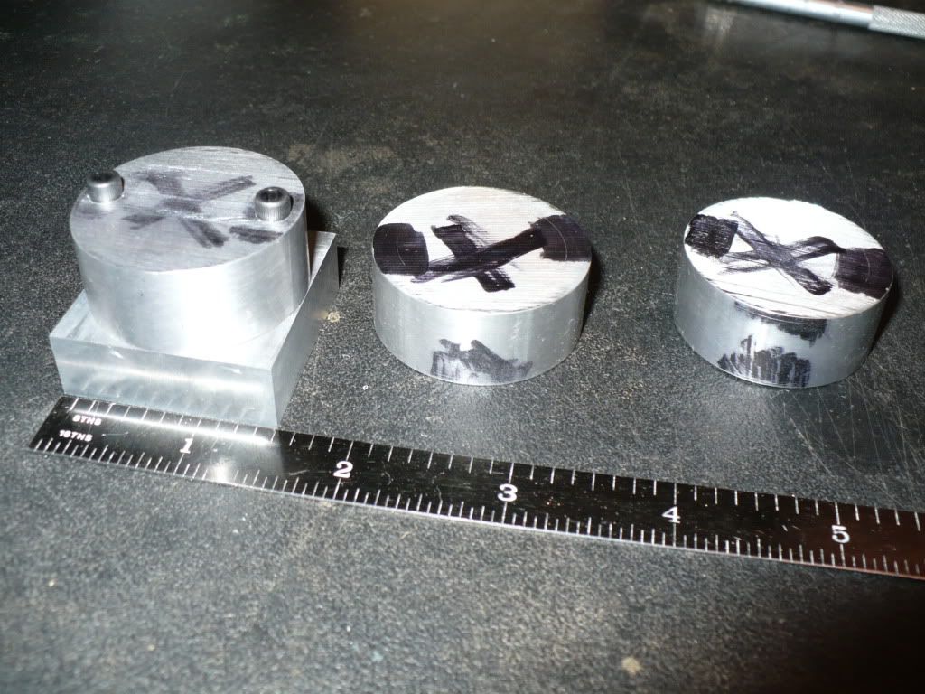
85) For today's post I made the cylinder heads that will be used on two horizontal, and one vertical engine. The heads for one horizontal, and one vertical F-Head engine are further down in the plan set and will be made at a later date.
To simplify The process I made a simple fixture. This way the heads could be bolted on, and changed out for each individual machining step with out breaking a set up.
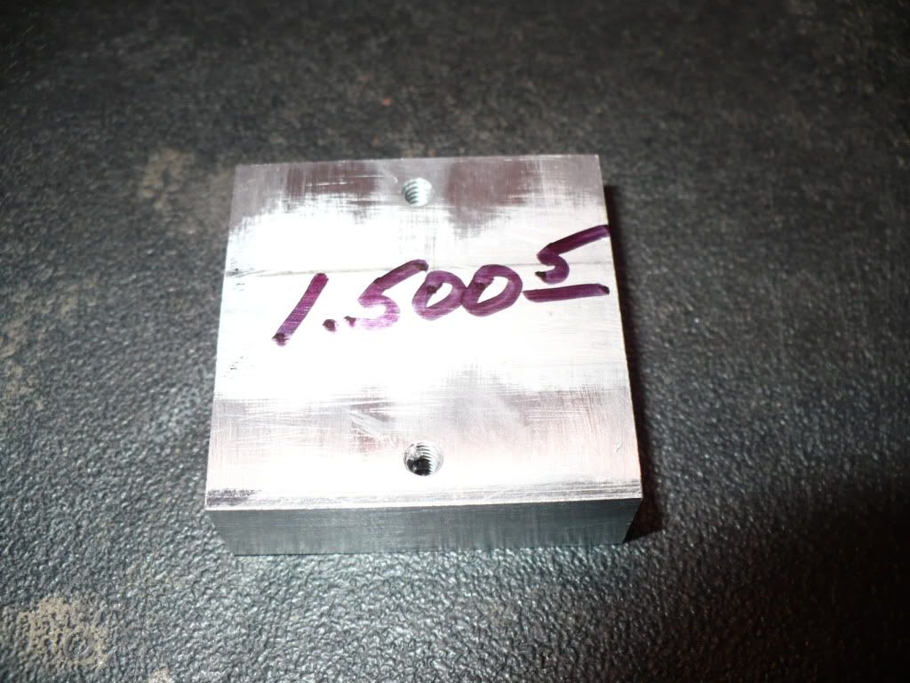
86) I band saw cut 1-1/2" in diameter aluminum bar stock blanks that will be be faced to their final width.
87) Ignore this picture, it should have been deleted. I drilled the mounting holes in one blank and decided that they should be trued up on the lathe first.
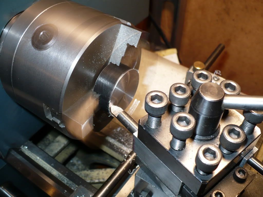
88) The picture below is back on track. This live action picture shows the blank being faced down to dimension. Notice the blurred jaws on the chuck. I was cranking the top slide hand wheel with one hand, and snapping pictures with the other. I could get away with this only because this was not the final facing cut.
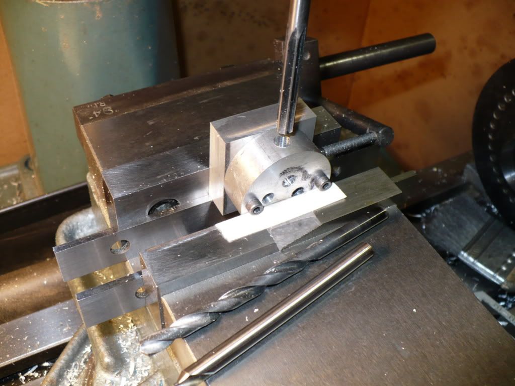
89) I drilled the two mounting stud holes on all the cylinder heads using this simple set up. After drilling one head with two table moves I changed out the work piece and did another. After getting the set up right and drilling one the heads, the rest were fast and fun.
90) I only need three heads for the project, but I decided it would be a good idea to make an extra one 'just in case'.
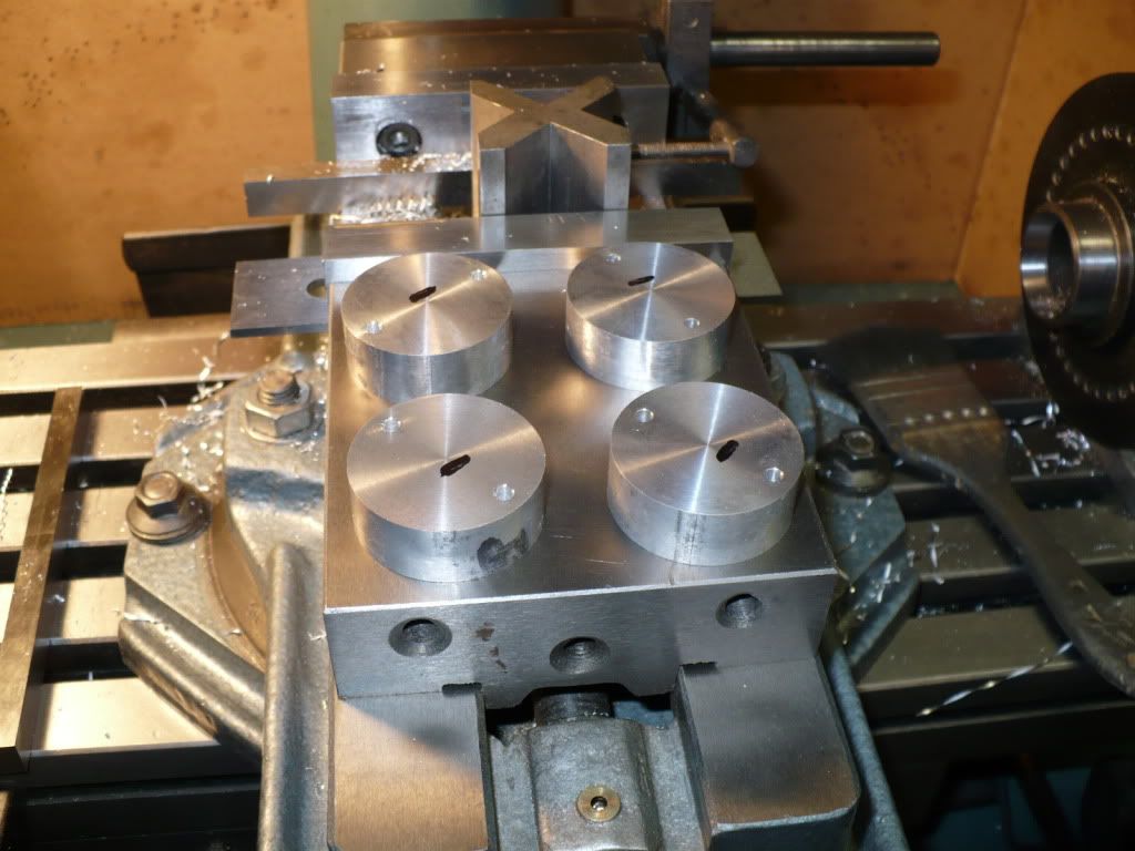
91) After shifting the table to the proper co-ordinate's I drilled and reamed the first of many holes.
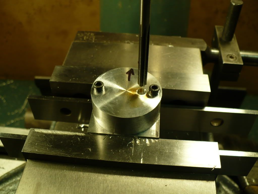
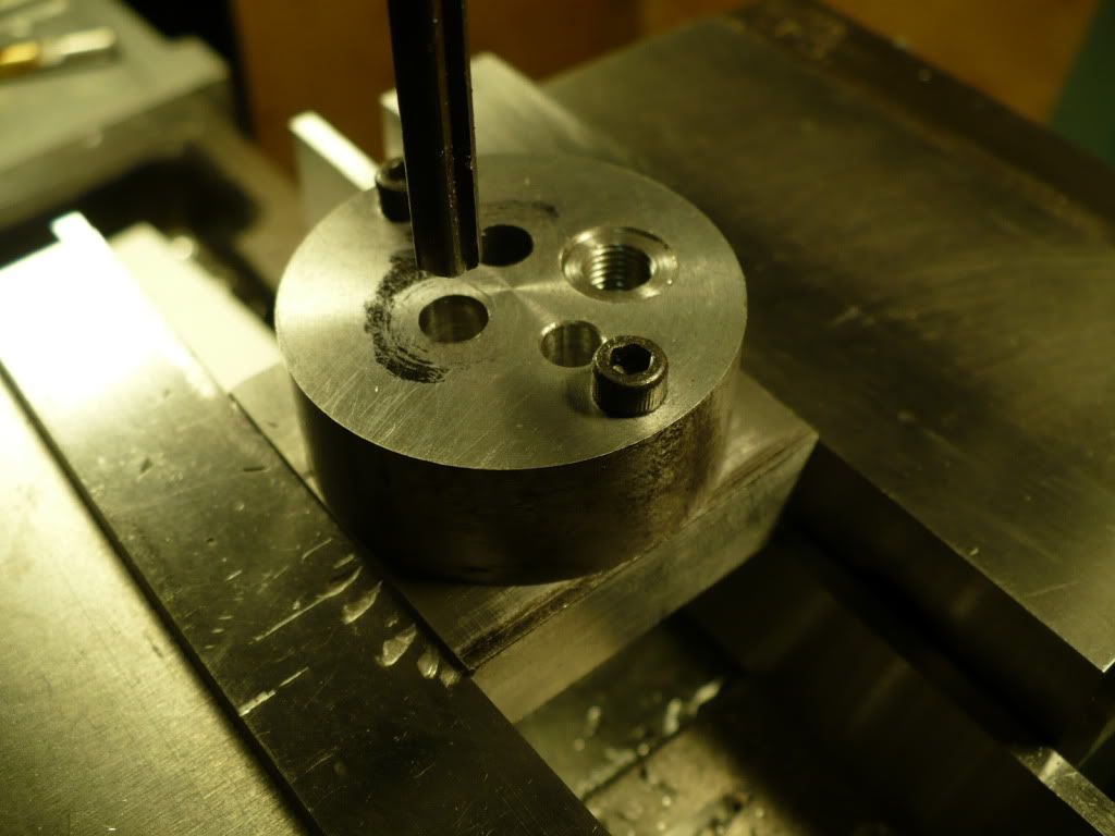
92) In this shot all the face holes finished. On this head I drilled, faced, and tapped for the spark plug. The others will have the spark plug hole on the side of the heads outer diameter.
93) Here the head and fixture were fliped up side down to add the intake hole. The exaust port and spark plug holes were added using an angle block.
94) All finished up and ready to go. I wish I could take the credit for those beautiful plugs. They are off the shelf Rimefire VR2L's, and they are real nice plugs. I bought them just to take the spark plug issue out of the picture when I try to get my engines to run. After studying a lot of designs and studying the ones I bought, making spark plugs dosn't seem to pose any difficulty I can't overcome. Its was just a minor fear of the unknown that made me decide to make my first attempts after I get a running engine, that I can try them out on.
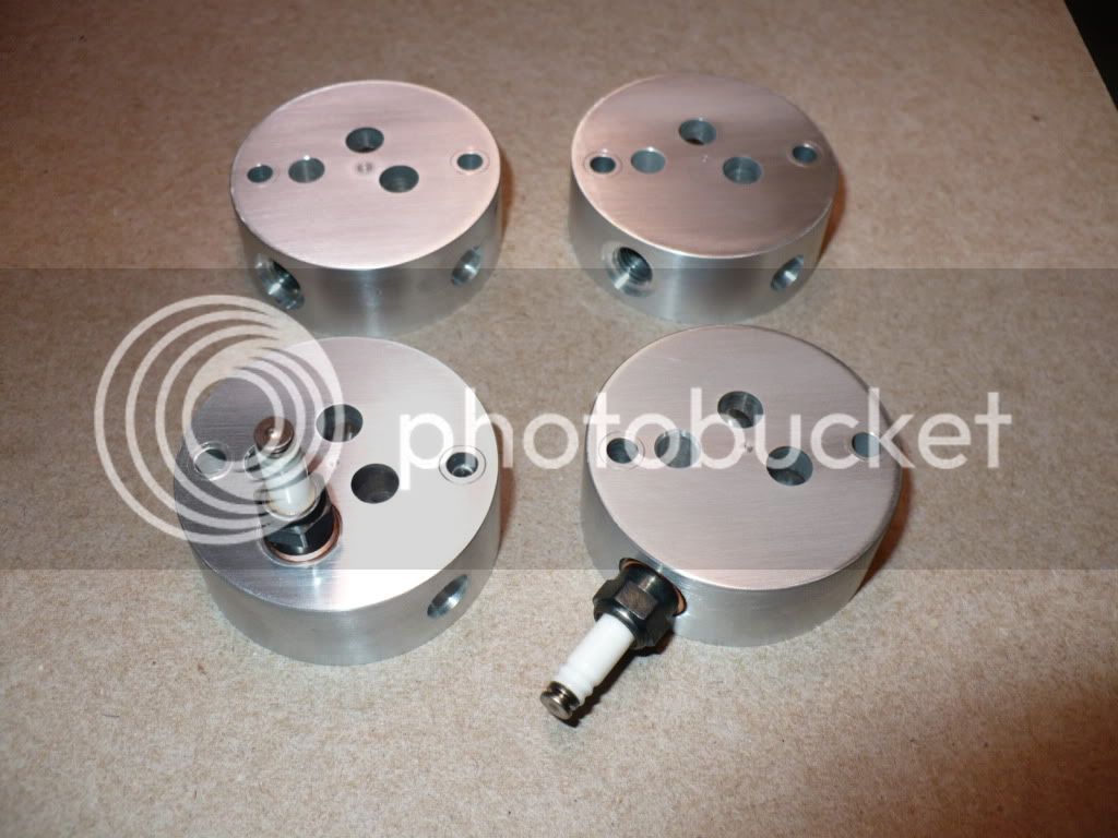
That's all for today, I hope you enjoyed the post.
-MB
To simplify The process I made a simple fixture. This way the heads could be bolted on, and changed out for each individual machining step with out breaking a set up.
86) I band saw cut 1-1/2" in diameter aluminum bar stock blanks that will be be faced to their final width.
87) Ignore this picture, it should have been deleted. I drilled the mounting holes in one blank and decided that they should be trued up on the lathe first.
88) The picture below is back on track. This live action picture shows the blank being faced down to dimension. Notice the blurred jaws on the chuck. I was cranking the top slide hand wheel with one hand, and snapping pictures with the other. I could get away with this only because this was not the final facing cut.
89) I drilled the two mounting stud holes on all the cylinder heads using this simple set up. After drilling one head with two table moves I changed out the work piece and did another. After getting the set up right and drilling one the heads, the rest were fast and fun.
90) I only need three heads for the project, but I decided it would be a good idea to make an extra one 'just in case'.
91) After shifting the table to the proper co-ordinate's I drilled and reamed the first of many holes.
92) In this shot all the face holes finished. On this head I drilled, faced, and tapped for the spark plug. The others will have the spark plug hole on the side of the heads outer diameter.
93) Here the head and fixture were fliped up side down to add the intake hole. The exaust port and spark plug holes were added using an angle block.
94) All finished up and ready to go. I wish I could take the credit for those beautiful plugs. They are off the shelf Rimefire VR2L's, and they are real nice plugs. I bought them just to take the spark plug issue out of the picture when I try to get my engines to run. After studying a lot of designs and studying the ones I bought, making spark plugs dosn't seem to pose any difficulty I can't overcome. Its was just a minor fear of the unknown that made me decide to make my first attempts after I get a running engine, that I can try them out on.
That's all for today, I hope you enjoyed the post.
-MB
- Joined
- Aug 8, 2009
- Messages
- 930
- Reaction score
- 12
MB...slow down...you're making me look bad. *beer* :big:
Similar threads
- Replies
- 356
- Views
- 56K