MB building Upshur Farm Engines.

Home Model Engine Machinist Forum

Help Support Home Model Engine Machinist Forum:

This site may earn a commission from merchant affiliate links, including eBay, Amazon, and others.
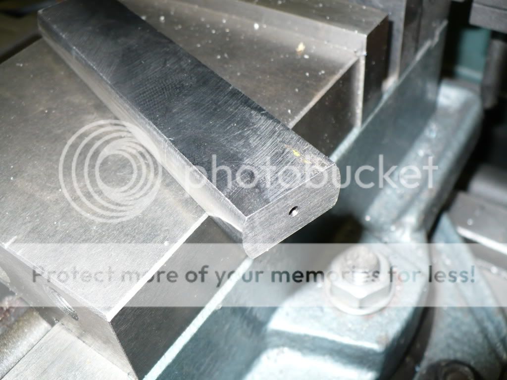
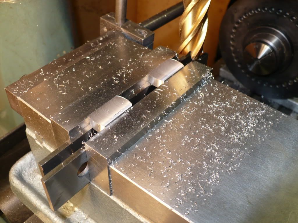
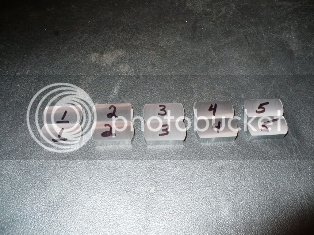
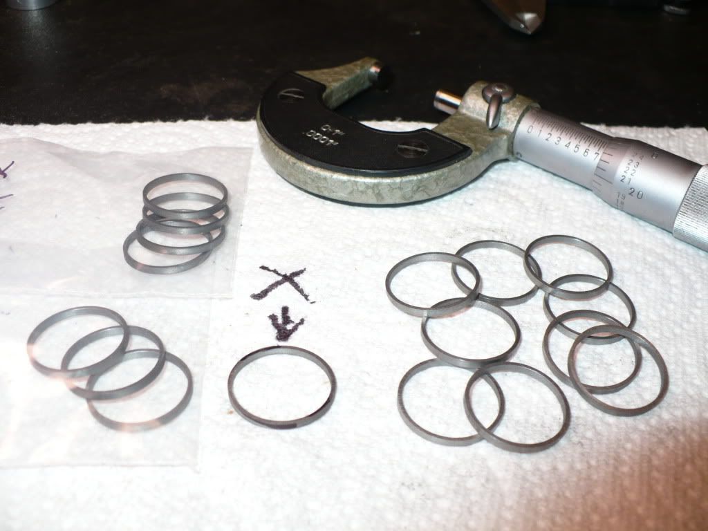
20) I decided to have a go at making the piston rings. I bored the ID and turned the OD on a cast iron bar (Sorry no pictures, I either forgot to take them or deleted them by accident) and used a parting tool to cut off the rings. A dial indicator and travel rod arrangement was used to get each one the same width. I needed 10 rings for the project, but only enough material to cut 16 rings. I would have liked more as a safety net since cutting then them of was quick and easy. I followed Hamilton's plans that specify the ring blanks to be .003" larger than the bore. The 'X' is pointing to the first one that came off undersized in width by a few thousands.

P1030999.jpg


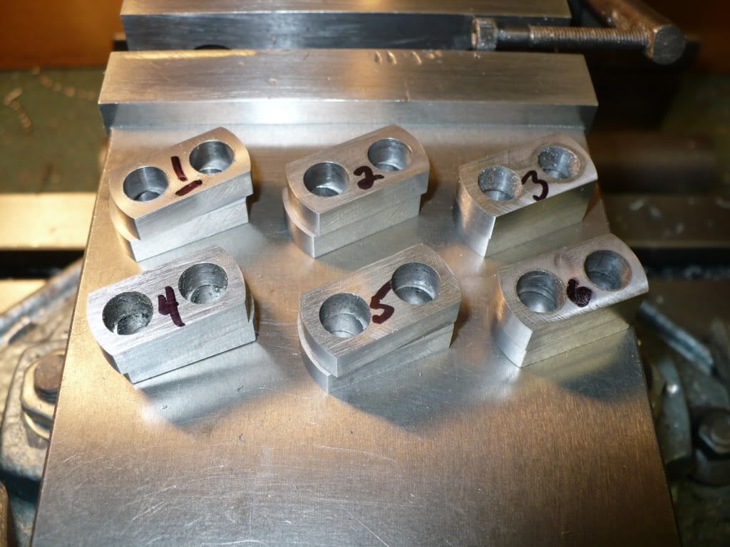
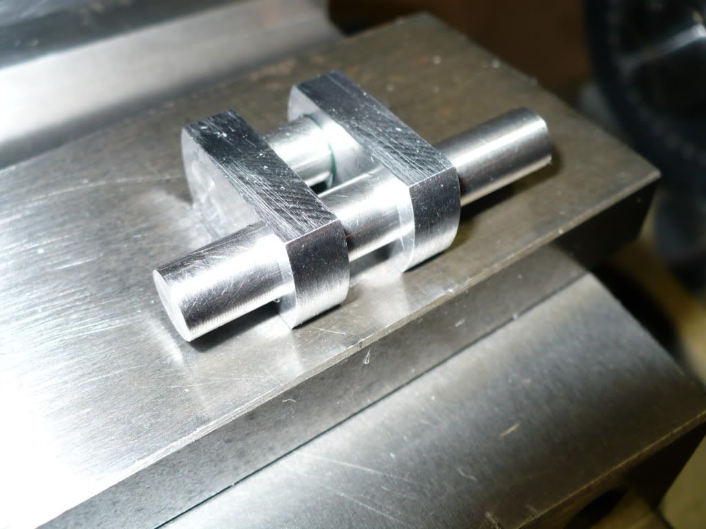
21) I set the rings off to the side and turned my attention to making the pistons. Nothing out of the ordinary here, just your basic aluminum pistons.

P1040003.jpg


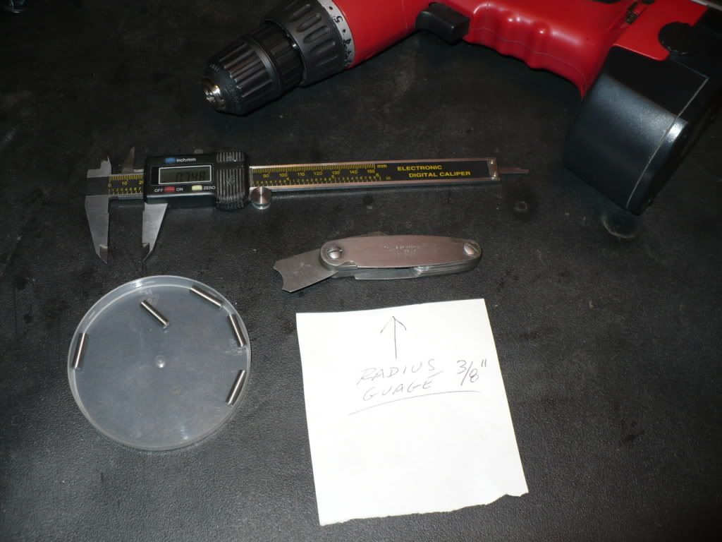
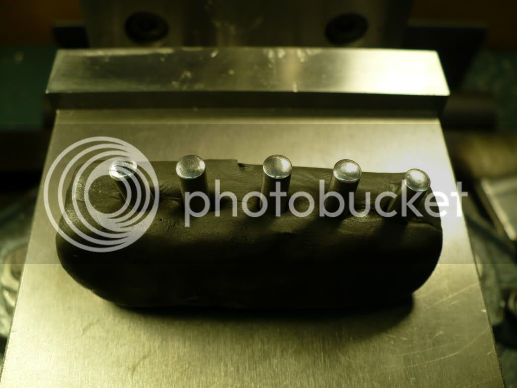
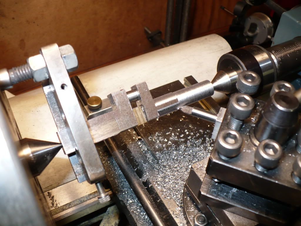
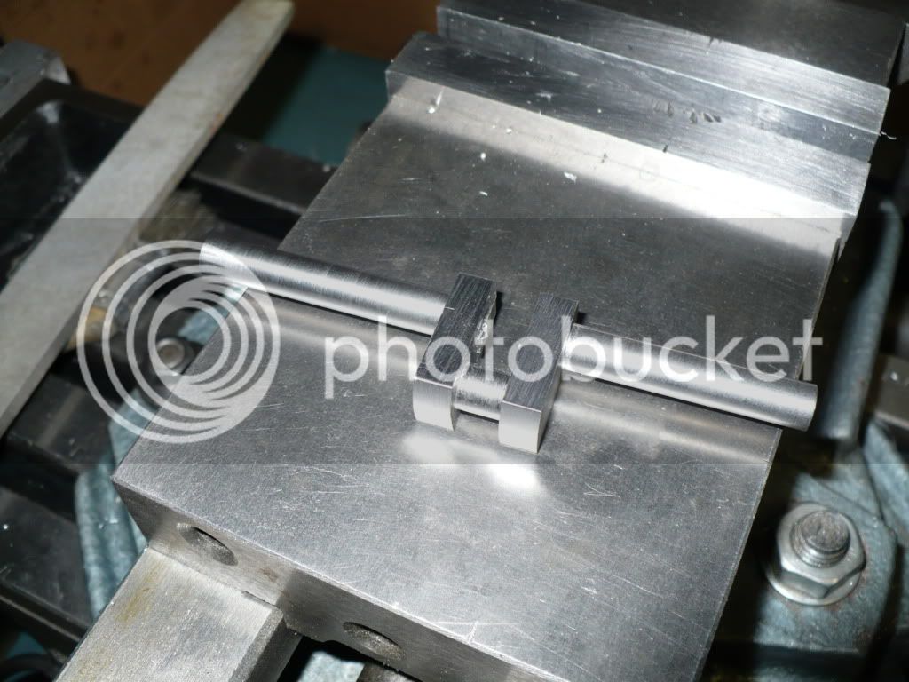
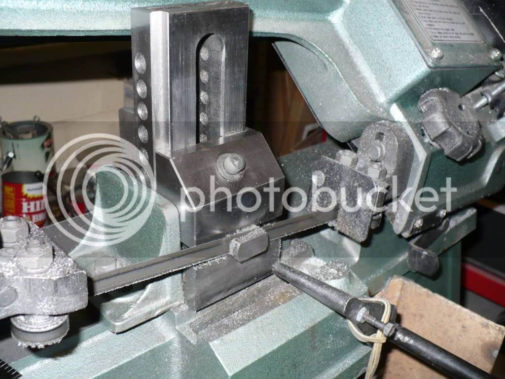
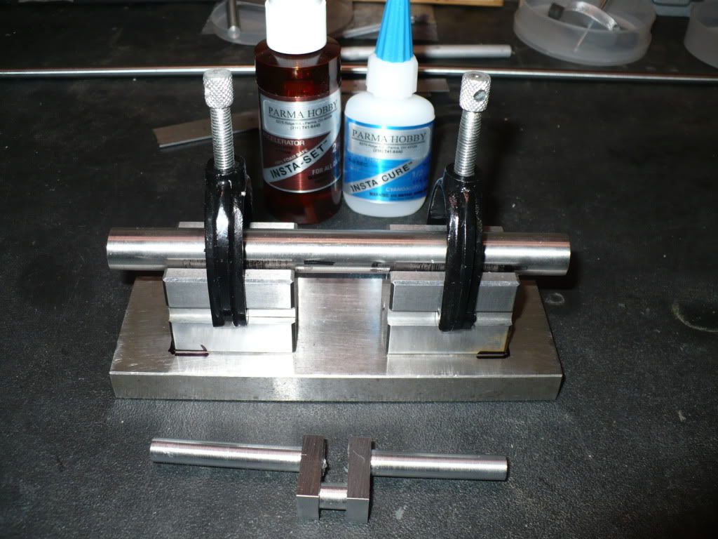
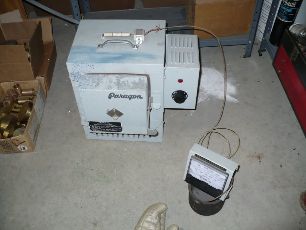
22) To anneal the rings I made a fixture with a rod that would hold the rings open and gaped to the specified amount. The fixture along with the rings were placed in my heat treating furnace. The temperature was brought up to 1000-F and held for just over an hour. Treating them all together in a controlled furnace would assure that the rings would be all good, (or bad). :'(

P1040004.jpg


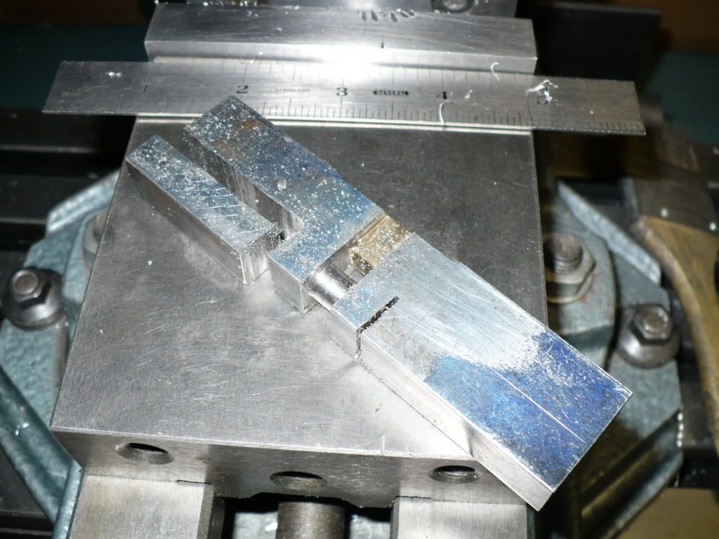
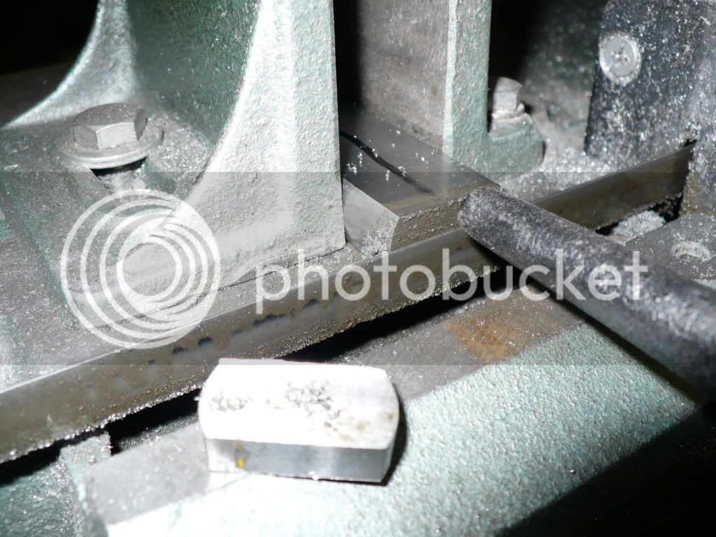
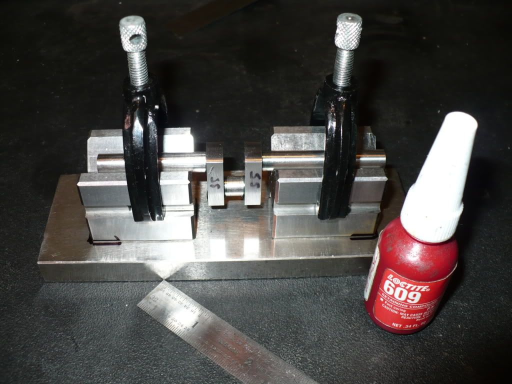
23) Before the rings got a good baking, I clamped each ring in my scrap filing/sawing vice and cut the split's with an Ex-acto saw. This gave me the .010" cut specified in the plans.

P1040007.jpg


24) Here the rings are all lined up in tight formation for their trip to a warmer place. The nuts hold them together were snugged up by hand, just in-case one of them were to object and get bent out of shape over the temperature increase! Rof}

P1040010.jpg


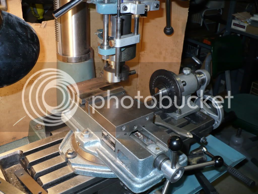
25) My easy bake oven. When the temperature dropped down to about 450-F I pulled out the fixture and rings for further cooling. I immediately shut the door and went up stairs to grab a ham-n-cheese sandwich. After wraping it up in foil I pop'd it in the oven. No sense in wasting good heat, besides I was hungry! :big:

P1040013.jpg


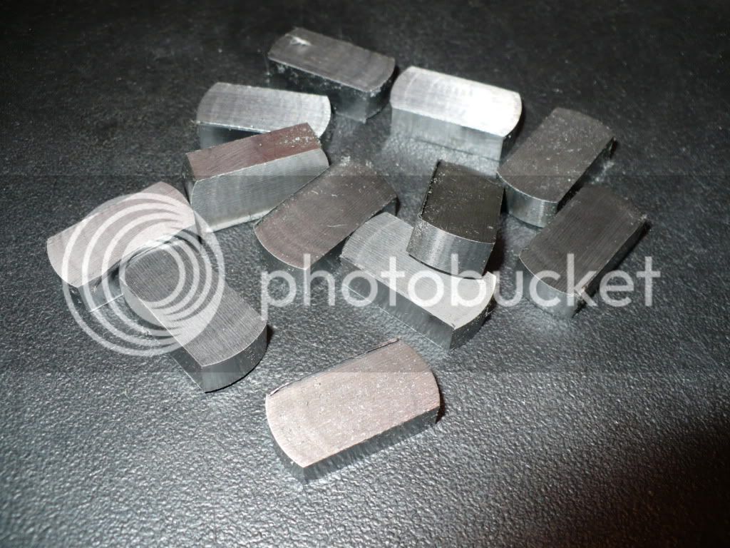
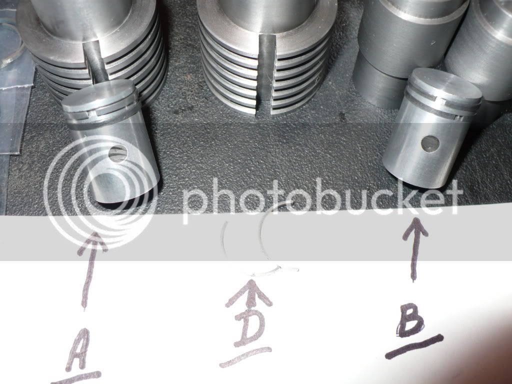
26) After the fixture cooled enough to handle with gloves, I removed the rings. They were sanded with #600 to width, and finished up with #1200 sand paper. They would not fit into the cylinder bores until I sanded the gaps out about .003". I pushed each one through its respective bore using the end of the piston, and double checked each gap and adjusted them till they measured .004 using a feeler gauge. After proper gaping they were installed on the pistons and pushed back and forth in the cylinder to make sure there was contact all the way around each ring. All the rings but one were making contact. After pushing it back and forth for quite a while the other ring became polish up (A) but the bad one made contact in just a few spots (rings on (B) show contact all around after being pushed through only twice) I pulled it off (A) and replaced it. The replacement ring showed contact all the way around after pushing it through a dozen times and checking. Problem solved! I took the offending ring (D) and spread it out till it finally bent and then broke in two! That'l teach ya ta mess with me! *knuppel2*

P1040022.jpg


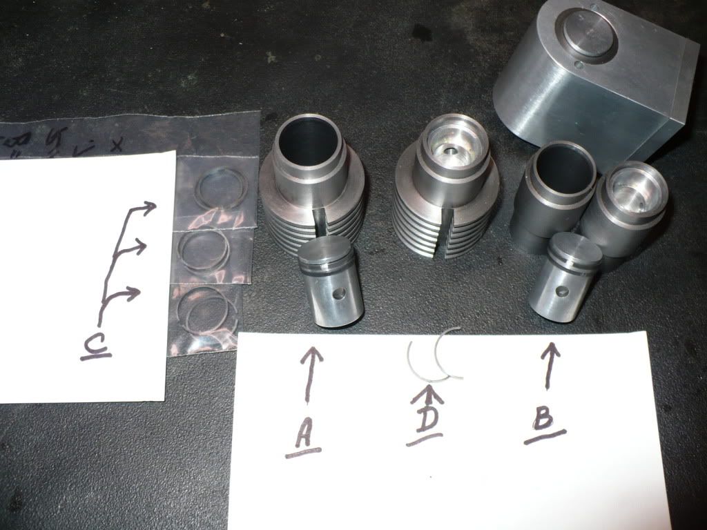
27) This close up (A) shows the top ring in full contact and smooth, and the lower replacement in full contact but still mostly discolored on the working surface. After a few strokes through the bore (B) is showing contact all the way around, as are the three other pistons/rings shown in their respective cylinders. (C) shows the rings left over due to zero breakage. Am I lucky or what! :eek:

P1040023.jpg


It turns out that making piston rings is not difficult at all. Since this was my first attempt, I made mistakes along the way, and I learned a lot. Next time they will turn out much better and with a little less fuss. Thm:

-MB


Good write up on the rings, MB.
actually a good photos and write ups on every thing.
Thanks.
Gail in NM
 
You just give me an excellent lesson on rings making :bow:
In my last attempt, i broke about a dozen before finding 6 that fit the cylinder, and then i managed to broke 2 more :(

Norberto
 
28) Making wrist pins is nothing special. I included them in today's post to show the grinding method I use. I started by cutting the pins about .012" to .015" oversize in length. With one chucked up and spinning in my cordless drill, I touch them against a running and well worn fine grit belt. I make light contact with the belt at 45 degrees and sweep to 90 degrees before pulling away. This is done on the unsupported part of the belt. After a few light sweeps the pin is measured, and the process continues on both ends till the target length is reached. With a little practice a pattern of removing .001" per pass aids in getting the length of all the pins plus or minus .001". During the process I keep checking the the ends using a 3/8" radius gauge to match the 3/4" piston and bore.

P1040027.jpg


29) The pins are finished up with 1200 grit paper and touched against a buffing wheel.

P1040030.jpg


30) Below is a blank cut from an aged piece of CRS I had laying around. Some refer to its condition as 'patina', to me its just plain old rust. Rof}
Hopefully it will become a crank shaft with a bit of machining.

P1040035.jpg


31) After center drilling the ends I scribed the dimensions shown in the plans and turned the rod journal.

P1040041.jpg


32) I cut out the excess material with my band-saw before turning tn the crank journals. I added a slip fit spacer block to keep the crank from collapsing between the centers.

P1040042.jpg


33) Here I'm machining the first side of the crank journal.

P1040047.jpg


34) And their it is all finished up and looking real good. The truth is that its totally useless! While I was finishing up the second side of the journal the finished side started to show a wobble. Apparently the stress in the CRS reared its ugly head and ruined my day. This is not a first time this has happened, but its probably the last time I'll chance this many hours on an attempt using unstable CRS.

P1040049.jpg


35) On to plan 'B'. To relieve my stress and the stress in the metal I machined another piece of CRS on all four sides. This is the blank I will cut slices from to become the webs in a 'built-up' crank shaft. I will use Loctite and pins for the final assembly.

P1040052.jpg


36) The blank is ready for slicing.

P1040055.jpg


37) And slicing and slicing.

P1040059.jpg


38) A set up used to get the last slice.

P1040061.jpg


39) And all done. I made an extra pair, and will probably need it with the way this build is going.

P1040062.jpg


40) I milled them to thickness in pairs just to be sure.

P1040063.jpg


41) A group shot of all the members in my 'Freshly Machined Web Club'. :big:

P1040065.jpg


42) The rod holes were drilled and reamed in pairs. Plan 'B' is well on its way.

P1040067.jpg


I'm thinking about making an assembly fixture to minimize the time spent on finishing up the crank assemblies, and to assure they turn out strait and usable. More on that in my next post.

-MB

 
I saw you had popped back in a while back. Sorry I hadn't said anything.
I'm glad you're back and I'm looking forward to your builds.
I saw your snack collection.
Decent...but insufficient.
A few years ago the KitKats would have been heresy for me (being a Mars employee at the time)...and having said that...you need some Butterfingers.
(I didn't say that.)
 
Hey!!! I've got a crankshaft just like yours.---Made the same way----Just as useless. We should start a "Useless Crankshaft Club".----On the other hand, I kinda don't like the sound of that too much-----Brian
 
Superior documenting going on here, MB. I appreciate it all that much more since I'm working on my version of this engine, in between others. Nice going on the rings too. I've popped those pics into my OneNote database for future ref.

If ya want, you can send me those extra rings and I'll send over some Kit Kats. :big:
 
Zee, I'm all out of candy! I didn't get even one Butterfinger. Help! :'(

Brian, No more clubs for me. I just became an honorary member of the 'Brain Dead Apprentice's Guild'. :wall:

Trout, You got a deal! Send over say...10-lbs (ten pounds) of Kit Kats. I suggest the use of a flat rate USPS box, you know, to save on shipping costs. Rof}

-MB
 
MB, sorry about the 1st crank.

I think you had the right procedure, just the wrong material. If you would give 1144 stress proof steel a try and use the same process, you would get much better results. The only problem is that 1144 is only available in round stock. It machines so nice that I buy round stock and machine bar stock out of it for use on critical parts.

It should be available at most steel supply shops and cost is slightly higher than CRS.
 
putputman said:
MB, sorry about the 1st crank.

I think you had the right procedure, just the wrong material. If you would give 1144 stress proof steel a try and use the same process, you would get much better results. The only problem is that 1144 is only available in round stock. It machines so nice that I buy round stock and machine bar stock out of it for use on critical parts.

It should be available at most steel supply shops and cost is slightly higher than CRS.

Thanks putputman, The idea of using the 1144 by sawing and machining a rectangle out of it is something I'll be trying sooner or later. I'm not going to even attempt another crank using 1018.

-MB
 
44) I cut the rod pins for the crank shafts from a bar of drill rod and machined them to length. Below is one already assembled with #609 Loctite. The longer pin is loose and it was used to aid in lining up the webs.

P1040071.jpg


45) With all 6 pairs of webs assembled and curing I cut a pair of rods for each set of webs that will become the crank shaft journals. Two different length rods were needed since the throw is not on the center of the crank shaft.

P1040075.jpg


46) I made a crank shaft assembly fixture by gluing two matching V-blocks to a hardened and ground plate. A 9/16 hardened and ground rod clamped down in the blocks lined them up so they could be set into a layer of super glue and accelerator. I came up with this idea to avoid sawing out of the shaft between the webs. Normally this becomes a mess using a hack saw and scars up the inside of the webs. It also requires accurate file work or milling to remove the remaining material needed to make the crank presentable. Since the clean up is time consuming and gives less than perfect results, I decided that making the fixture and using it carefully might be a better use of my time.

P1040079.jpg


47) The first crank was assembled, and the Loctite is curing. I hope this works out, if not I'll be a little 'cranky' (pun). :big:

P1040080.jpg


I'm debating if I should add pinning. Is it really necessary, or is it just used for peace of mind? The #609 Loctite is rated at 3000 psi on a 1/2" rod. I'll have to think about it a bit, and loose a little sleep before its over. :shrug:

-MB
 
I like your crank fixture MB. That would save a lot of filing time and such. I never would have thought of super glue to hold the v-blocks in place. I cant wait to see how it works out.

Did you score the surfaces of the webs and pins before locktiting in place?

Kel
 
kcmillin said:
I like your crank fixture MB. That would save a lot of filing time and such. I never would have thought of super glue to hold the v-blocks in place. I cant wait to see how it works out.

Did you score the surfaces of the webs and pins before locktiting in place?

Kel

Thanks Kel, I hope it works since I'm running out of ideas.

I didn't score any surface...didn't know I was needed, and never read or heard of it being mentioned. If its needed I'm in trouble again! :wall:

-MB
 
I cant say if scoring it is necessary or not, I am by no means an expert, but IMHO scoring the surface with light sandpaper would give the Locktite a place to "Lock Tite" I guess I was just thinking like paint, the microscopic scored surface gives paint a good place to "Grip". Kinda like VelCro.

Kel
 
Hey Rick,
The crank looks good. I know what the manufacturer says about the Loctite properties but I would pin it just to be on the safe side. That said, tomorrow we ought to know how true they are.. right!
George
 
gbritnell said:
Hey Rick,
The crank looks good. I know what the manufacturer says about the Loctite properties but I would pin it just to be on the safe side. That said, tomorrow we ought to know how true they are.. right!
George

Your right George they should and will be pinned. I keep he-hawin the subject hoping to rally the masses around to my way of thinking. This way when one of the cranks flies apart I can pass the blame on and say "Well you guys said it would work!" Rof}

-MB ;D
 
They say the morning after can be ugly, down from the high of the evening before.

I know that feeling today after checking my built up crank to find it wobbling.

Plan 'B' just came to an ugly end. Where do I go from here. :'(

-MB
 
MB, I would probably go back to the one-piece crank and try straightening it with a small press.

Also, if you decide to try another one-piece, you should make the following cuts before laying out the end markings and center drilling the pivot points on the ends (this crank has two throws, but the idea is the same):

57860862.jpg


Another idea would be to take down the two main journals a little bit at a time, alternating from one to the other and sneaking up on the final OD. That way you could turn out any warping that creeps in.

Any idea what went wrong it the built up crank?

Chuck
 
MB, if you decide to go back to a one piece crank, try making a fixture to turn the offset and the shafts. As long as you are making 5 cranks it will pay in time saved.
Take a look at my web site and see what I mean by a fixture. I use one on the Red Wings, Tiny I.C. & the Associated engines.

http://www.putputman.com/?folderKey=K-THGOLDDEePCd56_mT9jQ

Again, if you can locate some 1144, it would be worth your time.
 
Thanks Chuck and putputman, all the ideas you present are good.

However, there has been a new development! Being too stubborn to accept that my fixture and its assembly were flawed I tested the fixture and retested it many times using the following technique. I coated the original hardened and ground 9/16" rod with Prussian blue. I rotated it in the blocks a full turn with light and even pressure. This left an even blue line on both sides of the two v-blocks, and an even amount scraped off the rod all the way around and the full width of the blocks.

Next a piece of the original 5/16" d-rod used in the crank assembly was coated and showed the same positive result. I went back and forth with the rods and each time re-spreading the Prussian blue making the coat thinner and thinner as it deposited some on my finger each time. The only conclusion I can draw from these tests is that the fixture and it's alignment is not flawed, but dead on and strait.

Now I turned my attention to the wobbly crank. I tested it several times using a dial indicator on both ends of the journal and noticed that the reading was different each time and it would change based on how hard I tightened the collet up. I installed the 5/16" rod used to check the block's alinghment and the dial indicator showed the same varying .001 to .006" wobble as the crank shaft!

I checked the taper run-out on the collet-chuck's and its still within the .0002 (tenths) as it was in past tests. It looks like the collet is the culprit and not the crank shaft assembly after all!

The question is, how can I check the crank shaft run-out to be sure? scratch.gif

-MB
 

Latest posts

Back
Top