MB building Upshur Farm Engines.

Home Model Engine Machinist Forum

Help Support Home Model Engine Machinist Forum:

This site may earn a commission from merchant affiliate links, including eBay, Amazon, and others.
Being that i'm just a greenhorn, in this field (machining is a hobby to me), compared to the people who are well versed in this field, the way I would check it, drill and ream a hole through a rod that will accomadate and fully support one end of the crankshaft, as if you wer fitting a piston to a cylinder, then when this is fully supported, then turn the lathe on very slow, and check for any visible runout, on the far end of the crank.

Probably a Bad suggestion, I'm sure theres more precise ways of accomplishing it.

 
Hi Rick
There is only 1 way to check a crankshaft and that's between centers. Prior to assembling your parts the crank shaft pieces should be center drilled concentrically with the shaft. By that I'm saying when you chuck up your stock and before you center drill it run and indicator on it. It should be within .0003 at least. Then when everything is assembled, loctited and pinned place the crank between centers, headstock and tailstock and put it to the indicator test again. Check the shafts near the webs as it should be darn close out by the centers.

There is an ongoing discussion on one of the other forums about the quality and concentricity of machine collets. I can't speak for yours but it seems that these things can be all over the map, if not the collets themselves then the holders that they fit into. If your's can't be trusted to chuck up your material within .0002-.0003 then I would use a 4 jaw chuck.

Give me a call if you're still in a quandary.
George
 
hobby said:
Being that i'm just a greenhorn, in this field (machining is a hobby to me), compared to the people who are well versed in this field, the way I would check it, drill and ream a hole through a rod that will accomadate and fully support one end of the crankshaft, as if you wer fitting a piston to a cylinder, then when this is fully supported, then turn the lathe on very slow, and check for any visible runout, on the far end of the crank.

Probably a Bad suggestion, I'm sure theres more precise ways of accomplishing it.

Thanks hobby, I tried your suggestion and it worked! A Karma point for you! I chucked up a piece of brass rod and drilled it undersized and then reamed it with a 5/16" reamer. The dial indicator showed a .001 play between the rod and reamed hole. Rather than disturb the set up to split the fixture I slid the complete journal up to the webs into it and lightly held down the shaft close to the webs while rotating the crank. I rotated the webs with my finger. The indicator was on the very end of the out side journal and showed near zero run-out on both ends. The most I can detect is a tenth or two. Probably an anomaly of this method. Definitely not .001 to .006" run-out showing when chucked into the 5/16" collet.

If this crank shaft survives the pinning procedure It will become part of my build. ;D

-MB
 
gbritnell said:
Hi Rick
If your's can't be trusted to chuck up your material within .0002-.0003 then I would use a 4 jaw chuck.

Give me a call if you're still in a quandary.
George

Hi George. Apparently I need to check all of my collets and replace them if need be. The 5/16" is definatly going for a Monday ride in the big blue truck! :big:

At what distance from the collet does the run-out need to be within the .0002-.0003 that you specify?

-MB
 
Before you throw out that collet, you might want to make sure you didn't have a particle of metal or something between the chuck and the collet. I've had that happen to me in the past.

Chuck
 
cfellows said:
Before you throw out that collet, you might want to make sure you didn't have a particle of metal or something between the chuck and the collet. I've had that happen to me in the past.

Chuck

Thanks Chuck, that good advise. I'll take a good look, and hang on to it till I get a replacement if its needed.

-MB
 
48) In my last picture post the crank shaft assembly fixture I showed is working out well (plan B). I am allowing the Loctite a full 24 hour cure time. four crank shafts are assembled with two more to go.

While the Loctite is setting up I decided to start on the piston rods. The material I'm using is a hard brass plate I picked up on one of my regular visits to a local scrap yard. It machines and drills with a crackling sound unlike the #360 I'm used to working with, and it seems to machine more like a bronze.

P1040085.jpg


49) First I cut off two strips that will become the rod end caps.

P1040086.jpg


50) Two larger pieces were easily cut into six strips using a hand feed method with the saw in its vertical position.
These low cost import 4x6 horizontal/vertical band saws are a great time saver compared to hand sawing with a hack saw.

P1040088.jpg


51) The two narrow strips were also cut free hand, milled to dimension, and clearance drilled for their cap screws. I got on a roll with making these and forgot to snap pictures. ::)

P1040089.jpg


52) One end of each rod blank was center drilled for mounting in the lathe for the last finishing steps, and the other ends were tapped for the screws that will attach the rod end cap.

P1040090.jpg


53) The caps were also center drilled. This was done in one set-up when the two screw clearance holes were drilled. The picture was taken after a quick random test assembly of the caps. They all fitted up with out any problem.

P1040094.jpg


54) Since I forgot to mill down the 3/8" blanks to the specified .312" earlier. I did the milling with the caps mounted, and removed an equal amount from the top and bottom. The sides were milled to the same width and length, making a reusable set up possible. To make the crank journal holes it was more fun to use a stop set up and shut of the machine only for a tool change after all six pieces were center drilled, then drilled, and finally reamed. After shifting the table the process was repeated for the piston pin hole. The 'hole' process went much faster than shutting down and un-chucking/chucking for three tool changes on each hole. Opening and closing the vise was a much better and faster way for me.

P1040098.jpg


The next steps ahead will be much more difficult due to my lack of experience in making complex piston rods.

-MB


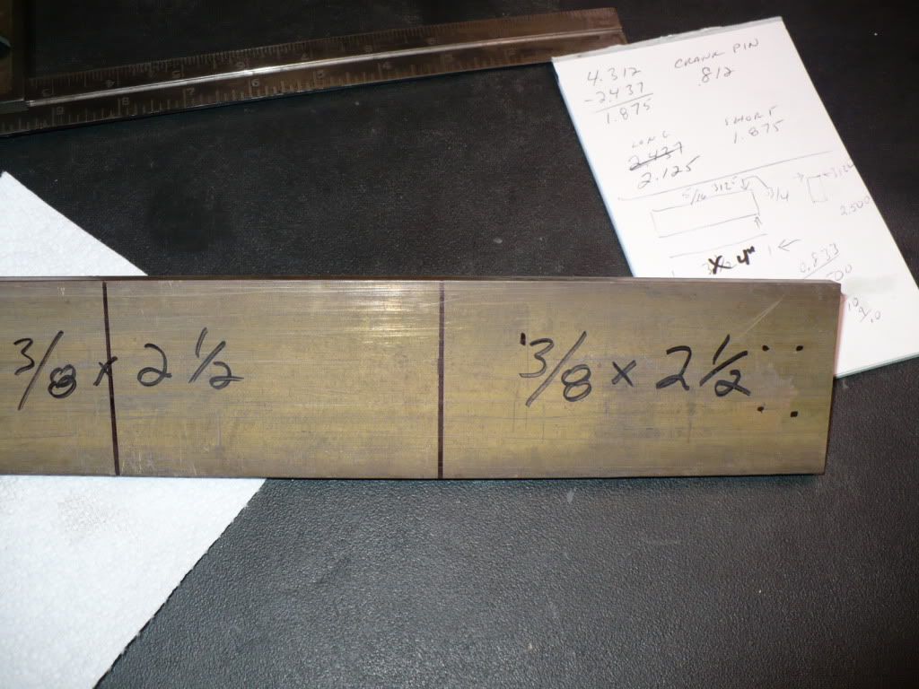
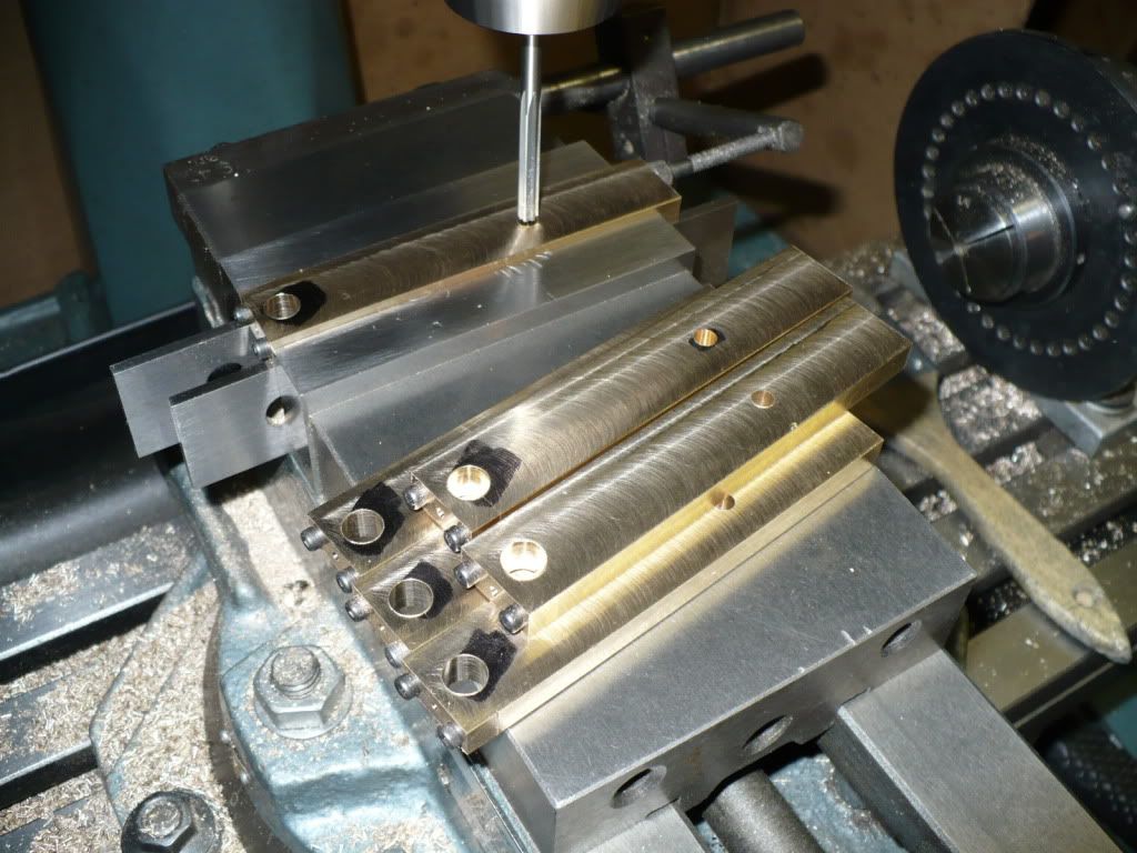
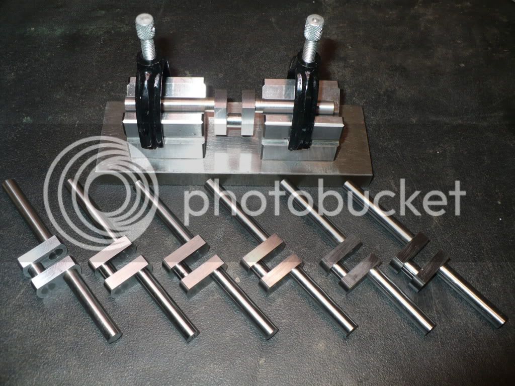
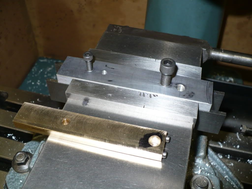
55) The next steps in making the piston rods required the use of a simple fixture. After milling a scrap piece of aluminum flat, two holes were drilled and tapped for tight fitting hold down bolts. The table was shifted over and a second set of holes were drilled and tapped. On this set the hold down bolt hole for the piston rods large end (crankshaft end) was shifted over to produce the specified taper on both sides of the piston rod.

P1040103.jpg


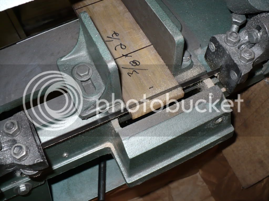
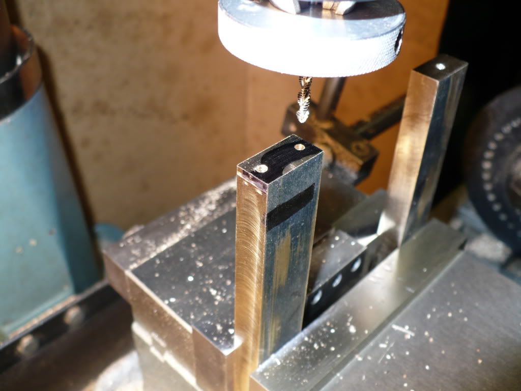
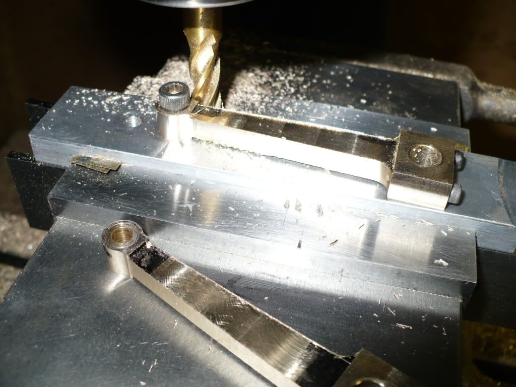
56) After I laid out the area that would be milled out, the end mill was lowered (away from the work) using a dial indicator mounted on the quill of the mill to the correct depth. This will give me the correct thickness when both sides are milled, centered on the blank. The first side of the first work piece was milled up to the guide lines, and the hand wheel was zeroed out. To mill up to the line on the other side of the milled out area, the hand wheel was turned in reverse and the number on the hand wheel written down with out disturbing it. Since I scribed all the sides on all the work pieces the counting of hand wheel turns was not necessary. All I had to do was watch the calibration on the hand wheel when approaching the guide lines.

P1040106.jpg


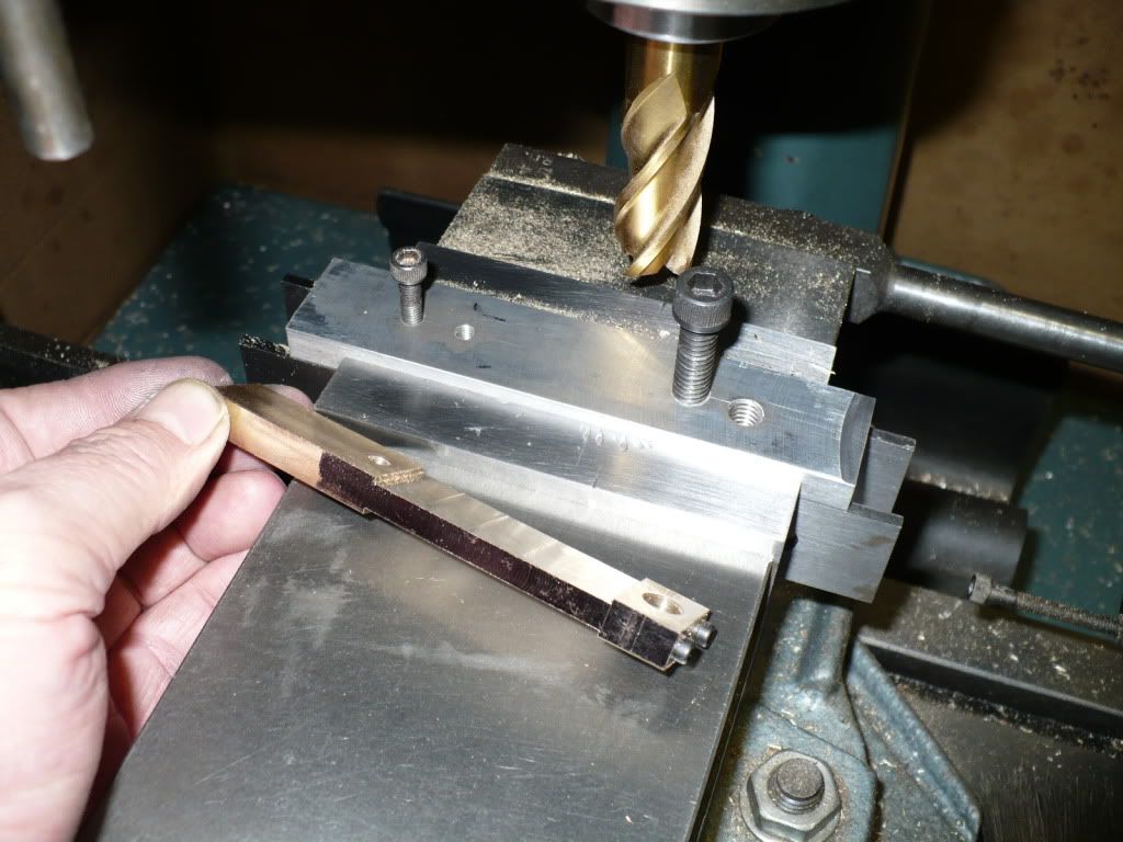
57) My mill is out of tram with the column leaning left since the day I brought it home. With out the knowledge or ability to correct it I need to sand pieces more than I care to, that are milled along the Y-axis. Most of the milling I do is along the X-axis that doesn't present much of a problem. I started to sand one of the piece's and it doesn't look too bad. Sanding up into the corners is going to be the harder part.

P1040108.jpg


58) To produce the taper on the rods I mounted the work piece in the second set of offset holes, (only one hole was offset). I made the taper with one cut staying short of my stop points and finished up with a light cut. I zeroed out both hand wheel calibration collars and wrote down the final number on the reverse cranked x-axis, the same procedure I used in picture #56. After the final cut I backed of both hand wheels .010" in preparation for the next side or piece, and raised the quill since the first rough cut would be started with a plunge cut. After the first piece was milled the process became routine and easy, creating identical pieces.

P1040109.jpg


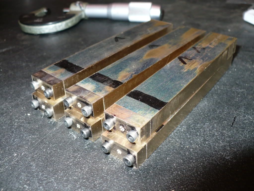
59) I made an extra piston rod. So far I haven't lost one to a silly mistake. If I had made only the 5 pieces needed... well you know how that would have ended up :big:!

P1040112.jpg


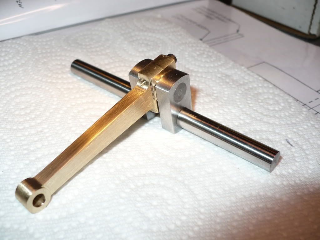
60) The next step was to turn a radius on the big end of the piston rods. I liked the basic square look of the rods but after turning one up I decide that all of them would get the same treatment. The plans also call for the small end to be "spherical", but my attempt at that detail was stopped short since I didn't care for the way it looked.

P1040116.jpg


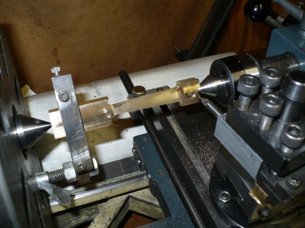
61) I went back to my fixture and gave the small ends of the rods a radius. I used thread-locker and snugged up the hold down bolt till I could barley rotate the work piece. The rod was set up in the same offset position were the tapered cut terminated. I only cut half the radius and flipped over the piece to make the second cut meet the first one on the end. I felt this was safer (cutting out of a corner) and would give a better result than going all the way around and finishing up into a corner were the piece usually grabs. It went real well and all the pieces were completed successfully and with confidence. To finish up the radius all the way around the small end, I raised the end mill to the same reading (depth) on my dial indicator that was used to mill out the web between the large and small end of the rods. All went well, and it was nice to get a handle on a repeatable way of milling the details on all six piston rods. :)

P1040119.jpg


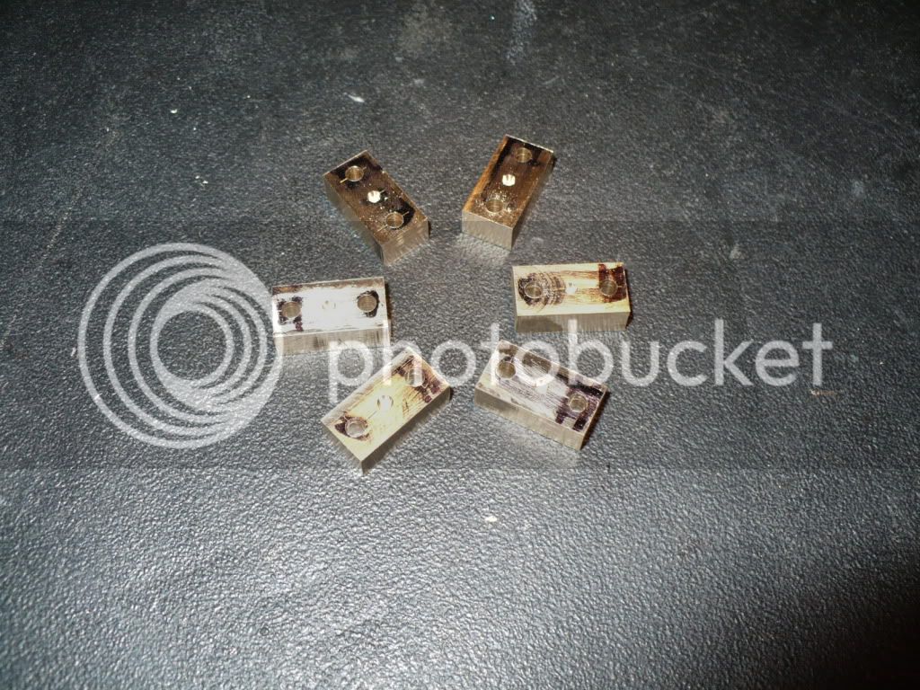
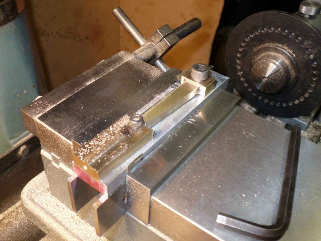
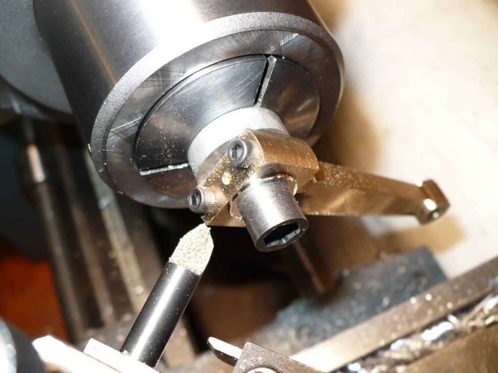
62) The final machining step was to create a .010" boss on both sides of the big end so that the entire face would not be rubbing up against the crank shaft webs. I made a simple fixture using the same hold down bolt used for the milling steps. After the first side was cut to the proper width and depth I locked the carriage and zeroed out the cross slide calibrated hand wheel. I backed out the top slide with cutter far enough to clear the next side to be cut, flipped the piece over and cut till I reached the zero mark on the calibrated collar. It went so fast and smooth I wished for more pieces to cut.

P1040124.jpg


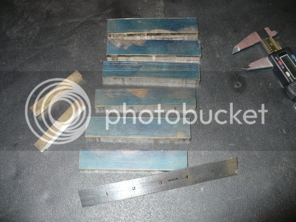
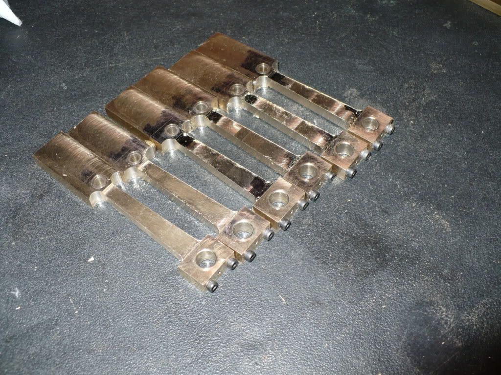
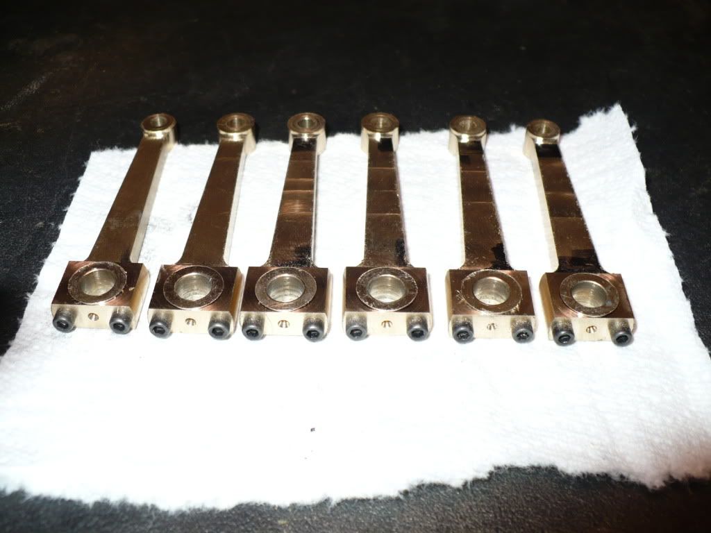
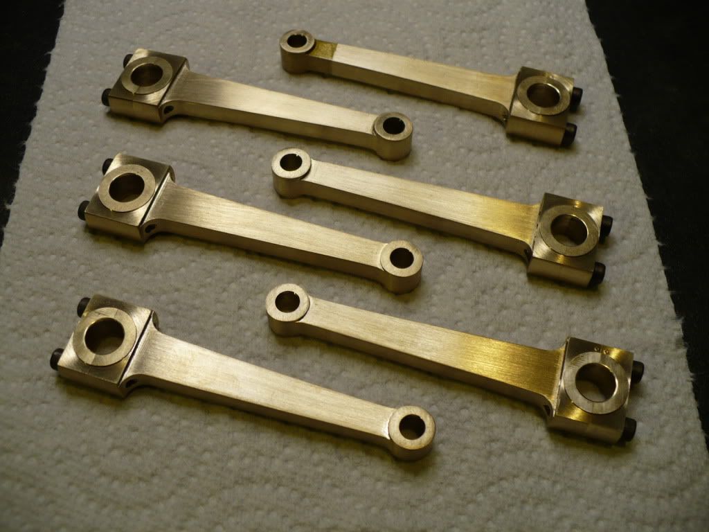
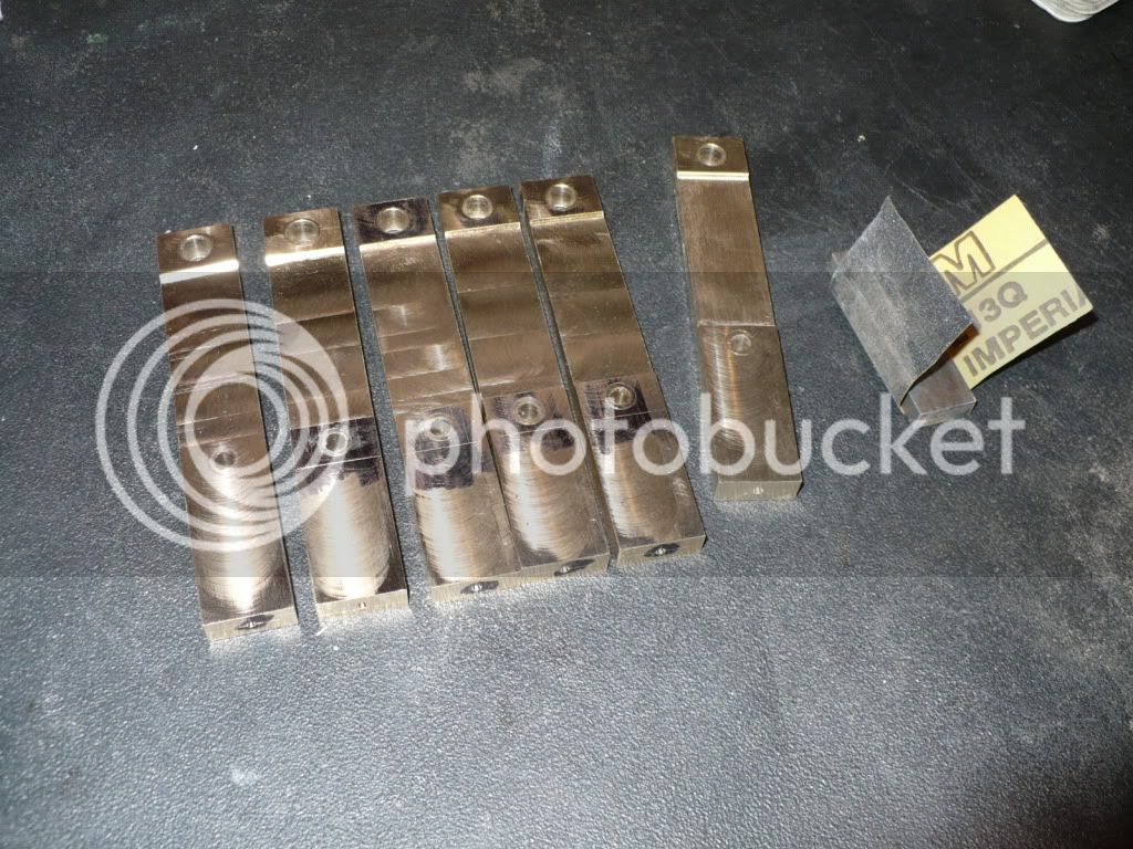
63) Below is a group photo of the semi-finished piston rods. The final step will be sanding them till they reach a presentable appearance. As much as I dread hand sanding, finishing up these rods will be a pleasure.

P1040125.jpg


I'm so pleased with today's outcome that I'm giving myself the rest of the day off! :bow:

-MB

 
I just couldn't leave it alone! :wall:

I started to file the con rods to remove the milling marks, and noticed the small end boss on one turned out a little choppy. Not a problem since the set up I used is still in place on the mill. All that's needed is to redo the small end radius by bringing the cutter in one or two thousands. With the work piece held with one hand the other turned the hand wheel to bring the cutter in. The cutter grabbed in the corner and pulled the rod from my fingers and into the cutter creating a gouge about .030" deep! The connecting rod must have been out of position when I brought the cutter in. Next time I will use a stop rod to avoid the positioning problem that I believe caused this.

I hate to throw one away since I spent a good amount of time making them. So... I made up a batch of JBW and patched the gouge. When it hardens I'll try to re-cut the radius again. Since It will need painting I won't use it on this build. I'm building five engines, and that is the sixth rod.

I removed the last crank shaft from my assembly fixture this morning and checked it out. It turned out nice and strait just like the rest of them. By using the fixture its almost impossible to get the line up wrong and end up with a bad crank.

Well, break is over so back down to the shop I go. I'll finish up the day by sanding the file marks off the con rods.

-MB
 
Metal Butcher said:
By using the fixture its almost impossible to get the line up wrong and end up with a bad crank.
-MB


Isn't it a good feeling, when a homemade fixture works good consistently, its like a project all of its own.
Fixture design and building is all part of the project as a whole.

It would be nice to see all the fixtures that were made with a finished project, to really be able to convey the amount of intricate work is done on the project.

You have a lot of clever fixture designs in all your builds.

Keep up the excellent work...
 
Thanks hobby. I find myself building more and more fixtures. Most of them are simple and take very little time to make, but they can save a lot more time in use, and especially when making duplicate parts. In the past I spent far to much time trying to figure out how to hold a work piece. Now I spend less time making and mounting a work piece to a simple fixtures made of a scrap piece. Fixtures also help to eliminate scraped parts caused by work piece shift when using a weak set-up. A good example is what happened to me today (my reply, #49). If I had used a stop-rod or stop-pin my piston rod would not have shifted due to a hand held eye-balled positioning. I made a mistake.

Hobby machining with out any formal training is an ongoing learning process based on mistakes.
Someday my mistakes will get sold for scrap, and bring in a tidy sum $$$! Rof}

-MB
 
Metal Butcher said:
Someday my mistakes will get sold for scrap, and bring in a tidy sum $$$! Rof}

-MB

Just think if we could take all of our scrap (mistakes workpieces), and build a model utilizing all those, it would make for some very interesting projects. Rof}

 
You're really putting on a good show, Rick. I finally got caught up with this thread, and what you've
got done is looking great! I liked that jig you made for heating your rings. Different than the way I
do it, but looks a lot handier (given a furnace). I wonder if a guy would get a similar result using charcoal
and putting the ring setup in a pipe packed with sand? Could be an alternative for guys lacking the furnace.

Good of you to show the warty side of making solid crankshafts. Made a few myself , and an alternative to
1144sp is HRS, which doesn't have the built up stresses of CRS. Both 1144 and HRS have worked well
for me, in that regard.

Thanks for all the pics, and your usual well written narrative!

Dean
 
MB - you really are cracking on ! Great job :bow: and very informative.

Regards, Arnold
 
Deanofid said:
I wonder if a guy would get a similar result using charcoal
and putting the ring setup in a pipe packed with sand? Could be an alternative for guys lacking the furnace.

Good of you to show the warty side of making solid crankshafts. Made a few myself , and an alternative to
1144sp is HRS, which doesn't have the built up stresses of CRS. Both 1144 and HRS have worked well
for me, in that regard.

Thanks for all the pics, and your usual well written narrative!

Dean

Hi Dean. The sand idea could work. With a hole in the side of the pipe for a pyrometer to monitor the temperature, and by shifting the pipe or charcoal around you could make temperature adjustments. Tricky... but do-able.

http://www.paragonweb.com/DT2-7_Digital_Hand-Held_Pyrometer_Degrees_F.cfm


I didn't have any hot rolled to try out, and have never tried to machine any. I heard its nasty stuff to machine. Maybe that's why cold rolled (CRS) is specified on most plans. Since the CRS seems to have a lot of built-in stress I'm surprised that any cranks have been successfully made by others. I haven't had that kind luck with the stuff, so I won't attempt using it on another crank. Its just too risky given the amount of time it takes me to machine one up.

-MB
 
64) The crank shafts are finished except for the pinning and a final sanding after the pins are driven in. I need to order the correct size dowel pins. I'll do that at a latter date when I have enough items to place a minimum order from an online supplier. The six cranks laying on the bench are built up from individual pieces, and the seventh one shown in the fixture was machined from solid. It warped during the process, and although it looks good, its totally useless. I tried to straiten it without any luck.

P1040132.jpg


65) To finish up the piston rods the holes were de-burred and checked with the corresponding reamers. After a little sand papering their finished. The last one at the top of the picture is the one that got pulled into the cutter. I filled the area with JB Weld and re-machined the entire profile. I went over the filler with some brass colored paint that doesn't really help much. Since I only need five good rods I keep it for a future project that might work with a painted rod.

P1040135.jpg


66) After a test fitting the rods and cranks were wraped up and stored away. It will be quite a while till I see them again at assembly time.

P1040150.jpg


After sanding all day yesterday, I woke up today with a really sore right thumb and forefinger. So sore, that I have to flick a lighter with my left hand to light up a cigar! :big:

Mommy, can you kiss my boo-boo. Rof}

-MB

 
MetalButcher---Excellent work. I know what you mean about 'sanding finger syndrome'.----Hurts like heck!!!!----Brian
 
Those rod and crank assemblies are beautiful to say the least very nice!
:bow: :bow: :bow: :bow: :bow: :bow: :bow:
 
work of art
i love it
 

Latest posts

Back
Top