MB building Upshur Farm Engines.

Home Model Engine Machinist Forum

Help Support Home Model Engine Machinist Forum:

This site may earn a commission from merchant affiliate links, including eBay, Amazon, and others.
Great news!

The first engine is assembled complete with flywheels, and its running in hit-n-miss mode!

More details in a day or two. :big:

-MB
 
Great News Indeed MB!

The antici..................pation. Cant wait to see the vid.

Kel
 
I'm exhausted just watching the builds, can't imagine how relieved you must be! :) Can't wait to see the video.

Chuck
 
Metal Butcher said:
Great news!

The first engine is assembled complete with flywheels, and its running in hit-n-miss mode!

More details in a day or two. :big:

-MB

Done up right and it runs! That's great news, Rick.
Hey, sorry about the bum steer on the silicone tubing. Didn't realize it would only take glow fuel.
Good thing Gail was on the clock!

Dean
 
Deanofid said:
Done up right and it runs! That's great news, Rick.
Hey, sorry about the bum steer on the silicone tubing. Didn't realize it would only take glow fuel.
Good thing Gail was on the clock!

Dean

Thanks Dean! The first one runs. and that's really good news!

No problems with the tubing suggestion. Its easy to think that 'air plane fuel line' would work, but it won't.

-MB
 
#349 With all of the wiring finished on the remote CDI box and the engine, the last ignition component was the installation of the spark plug. Since the cylinder head is aluminum it was a good idea to add some anti-seize to the threads on the plug prior to installation.

P1050479.jpg


#350 The first pair of fly wheels was prepped, and then all of the machining steps were completed prior to painting them to match the water cooled version. In the picture below the governor carrier was test fitted.

P1050493.jpg


#351 I was only able to get the engine to fire once on every 4 to 5 attempts at starting, and after about two hours I gave up and called George Britnell. George offered to come over to check out my engine to see why it wouldn't run. It turned out that I had my needle valve turned out way to far, and in a range of adjustment that was too rich. George got the engine running by starting at a near closed position, and fine tuning the needle valve adjustment slowly till the engine wood run. The setting is very critical with the needle valve that I made, and the needle valve needs to be replaced with one that has a more gradual taper, and will allow more leeway in adjustment. With the engine running nicely it shut off after a good warm up and the fuel flow stopped. Fine bubbles were forming in the fuel line cutting off the flow of fuel indicating a vapor lock. George recommended that I make a block to insulate the carburetor from heat coming from the cylinder head.

I made a simple isolation bushing out of Delrin and it solved the problem. I was able to run the engine this morning for 38 minutes, and drain the tank with no formation of vapor bubbles. The insulator is between the cylinder head and the carburetor.

P1050503.jpg


#352 Here's another picture of the engine from the rear.

P1050508.jpg


#353 Another picture showing the governor weights and springs.

P1050509.jpg


I'm trying to make a video with no luck. I'm being told that something is wrong with my camera. It shuts down and the screen says to check the memory card. I tried two other ones, and the same problem continues. :(

Video link: http://www.homemodelenginemachinist.com/index.php?topic=13944.0


-MB


I had that problem with one of my cameras until I formatted card in the camera then worked fine.
 
Beautiful, MB. Is it just me, or does that color just look better and better over time? :bow:

Rudy
 
doc1955 said:
I had that problem with one of my cameras until I formatted card in the camera then worked fine.

Hi Doc. We formatted the card and the shut down occurred again, at about a minute and a half into the video. After that the camera would not erase the data, so we re-formatted again.
The second time around I stopped the taping after 40 seconds to prevent the shut down, which would corrupt the video making it unless. I made a second video and stopped it at about 1-1/2 minutes. Afterward the camera did erase the data. 'Picture guy's' conclusion is that the camera has an intermittent problem and that it should be replaced.

The batteries will only hold a charge for about 24 hours, so I'm hopeful that the new set I ordered will solve the problem.

-MB
 
rudydubya said:
Beautiful, MB. Is it just me, or does that color just look better and better over time? :bow:

Rudy

Thanks Rudy. I'm very fond of the color too, but to keep it from getting old, only the water cooled one will be that color. The rest were not planned to be painted at all, but with the warmer weather coming I might just decide to paint one (or more) of them after their maiden run. I keep looking for another color that I like as much as the green with no luck so far.

I have a question, if you don't mind. What did you use for the springs on your governor?

Mine are .180 x 1.00 long (to the very end of the loops where they hook on) made of .013 wire. Using .012 or .011 might slow the cycling down a bit, but I'm really happy with the speed as it is, and don't feel compelled to try any change at the moment.

-MB
 
Rick----I can feel your excitement/frustration/delirious joy/confusion/pride----and so on!!!! Congratulations on your runner. I (among thousands) am anticipating the video.----Brian
 
Brian Rupnow said:
Rick----I can feel your excitement/frustration/delirious joy/confusion/pride----and so on!!!! Congratulations on your runner. I (among thousands) am anticipating the video.----Brian

Thanks Brian! Yes all of the above! With one engine done, its just the beginning of a very hectic time for me. No more time or need to think about how to proceed. Its all been worked out, and the result is the #1 engine complete and in running order. With time running short I must move forward with all the energy I can muster.

I have to machine four more sets of fly wheels, four more carburetor insulators, and other misc tasks before the final assembly. I'm doing one engine at a time, and I will post videos as each engine is deemed finished.

I started to machine the second set of flywheels today. It's very time consuming and intense, and there's no provision for error.

-MB
 
Metal Butcher said:
...Rudy... I have a question, if you don't mind. What did you use for the springs on your governor?...Mine are .180 x 1.00 long (to the very end of the loops where they hook on) made of .013 wire. Using .012 or .011 might slow the cycling down a bit, but I'm really happy with the speed as it is, and don't feel compelled to try any change at the moment.

-MB

MB, my springs are 0.015" music wire, 57 turns, plus or minus a turn, closely spaced, 0.185" OD and 0.875" long, not counting the hooks, so they're a bit longer than yours. My weights are about 0.010" shorter than the plans called for, so they weigh a little less, and I used a 0.27" wide strip of 0.005" brass shim stock for the arm return spring. I played around with different combinations of springs and weights trying to get as much "coast" as I could.

Regards,
Rudy
 
MB,
It had been a while since I had checked in on your build(s) so last night I reread the entire thread. Such an amazing and well documented build it is too...I can't even imagine working on multiple engines at one time even though some of the parts are similar or identical. I am particularly interested in your use of the S/S CDI system as I plan on using the same system... so I gleaned some good info. from that part of the thread as well. The video you posted separately only confirms a job VERY well done!!! Looking forward to seeing the rest of them come to life too.

Regards,
Bill
 

Thanks Rudy. The info you provided was helpful in me understanding the relationship between the weight of the 'weights' and their springs. I made my weights slightly longer (heavier) than the plan. If I cut them down a bit, or make them from lighter aluminum, that would effectively reduce the engines speed without changing the spring wire to a smaller diameter.

I can fine tune this area latter. Right now my goal is to finish up with the last of the machining, and get all five in good running order.

-MB
 
b.lindsey said:
MB,
It had been a while since I had checked in on your build(s) so last night I reread the entire thread. Such an amazing and well documented build it is too...I can't even imagine working on multiple engines at one time even though some of the parts are similar or identical. I am particularly interested in your use of the S/S CDI system as I plan on using the same system... so I gleaned some good info. from that part of the thread as well. The video you posted separately only confirms a job VERY well done!!! Looking forward to seeing the rest of them come to life too.

Regards,
Bill

At first I was overwhelmed with putting together the ignition system, just soldering the wires and getting the correct shrink tubing was all new to me. Eventually I got it all figured out and assembled.

I bought the 'basic' S/S system and added my own on/off switch, hall sensors, batteries and holder. I already had a 4x AA battery quick charger and the Nmh batteries. Its a really simple system to put together if you know how to solder the hall sensor wires together. Or you can buy a pre-wired sensor that simply plugs in to the CDI system.
The unit draws very little power, I've had the ignition on for 4 hours or more, and have not re-charged the batteries yet! It seemed to be the best system for my needs, and its proven itself beyond a doubt.

Rechargeable (Nmh) batteries are very reasonably priced (E-bay, or store) and easy to transport, so taking an extra set and/or a small wall charger to a weekend engine show is as easy as it gets.

I bought the 'basic single' for $55.

http://www.cncengines.com/ic.html

-MB


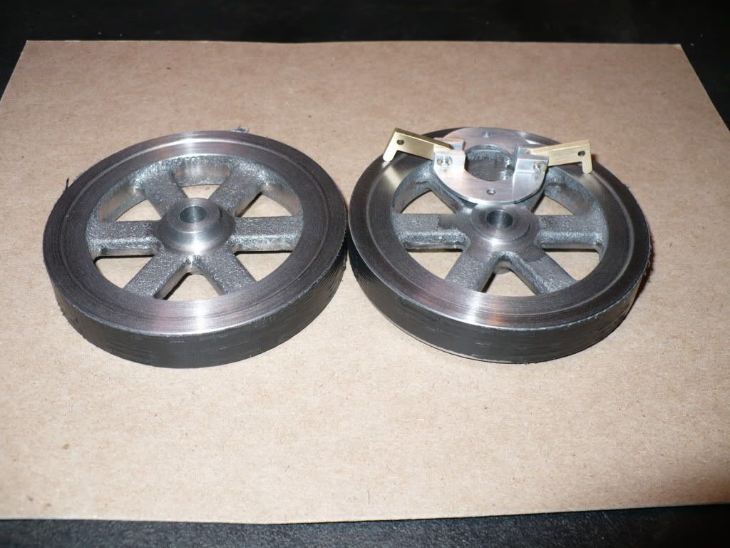
#354 I finished up all the lathe work on the next two flywheels and added a stepped profile on the sides of the flywheels. They turned out well, and I'm very pleased. The outer edges of the rims were protected with a layer of black duct tape. Silver will work too! :D

P1050525.jpg


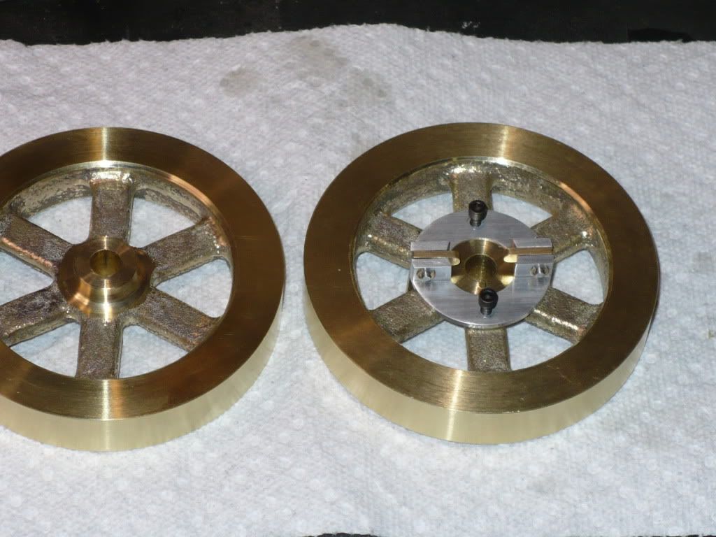
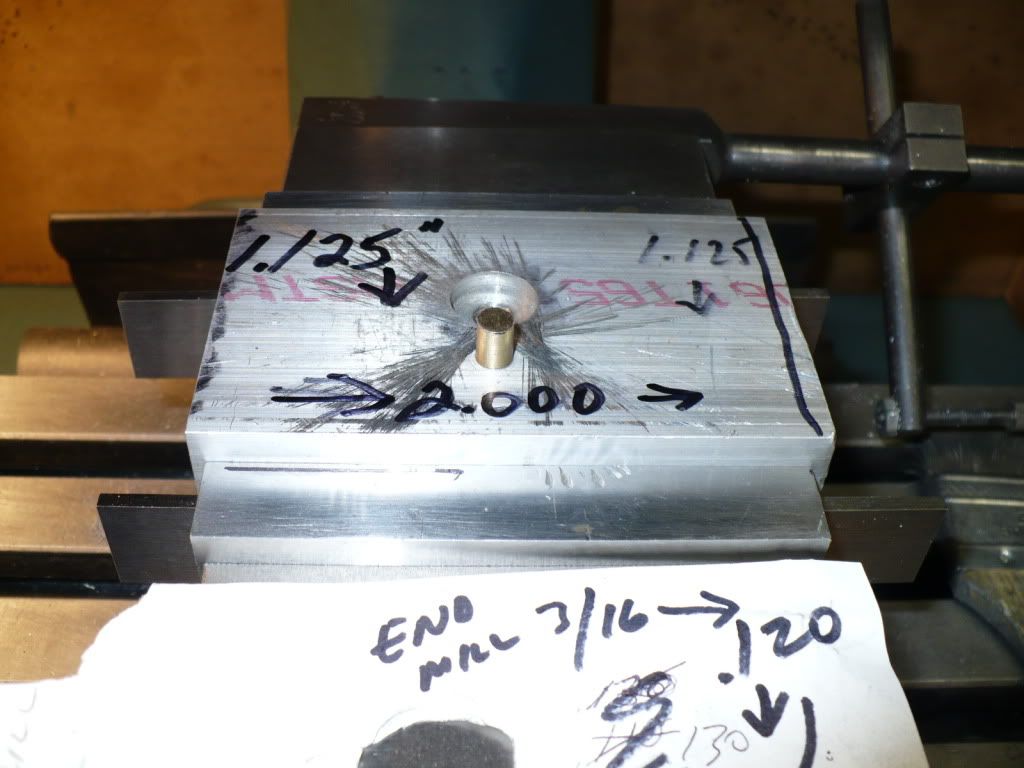
#355 I mounted the flywheel in a fixture and shifted .531" off center to drill and tap the two 4-40 screw holes that will hold the carrier in place. This governor carrier is mounted on the inside of the flywheel used on the push rod side of the engine. I checked the location of the holes with the carrier in place just to verify before drilling.

P1050528.jpg


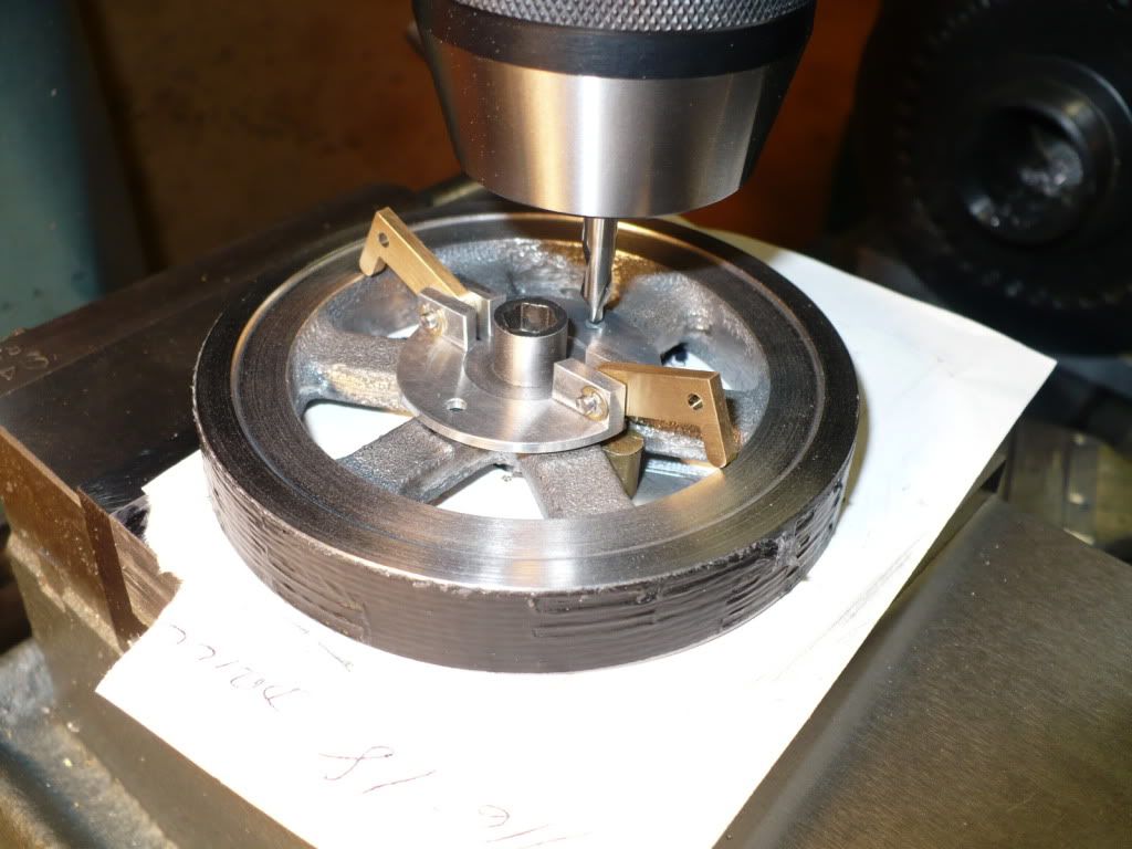
#356 I used the same fixture and a 3/16" end mill to create a pocket for the arms on the carrier. After milling out the first pocket the flywheel was rotated 180* to mill the one on the other side. The arms are held in place with springs and rest on the outer .625" hub diameter when the engine is not running. The outside dimensions on the parts in this area are critical, and the plans proved to be correct.

P1050530.jpg


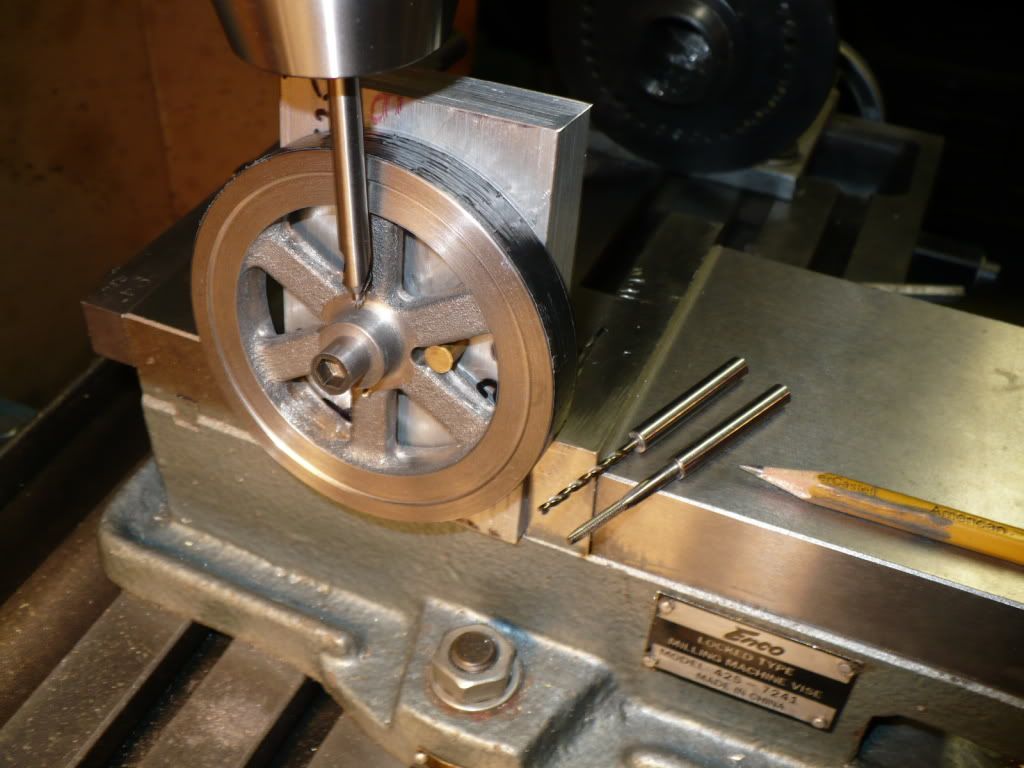
#357 Here's the simple fixture I made. The brass pin was too tall and wouldn't allow a test fit of the carrier, so I 'fine tuned' it with a hack saw and file!

P1050533.jpg


#358 Here the fixture is tilted over and rotated to do triple duty. It was used to center the flywheel bore to drill and tap it for a 4-40 set screw with out any fuss.
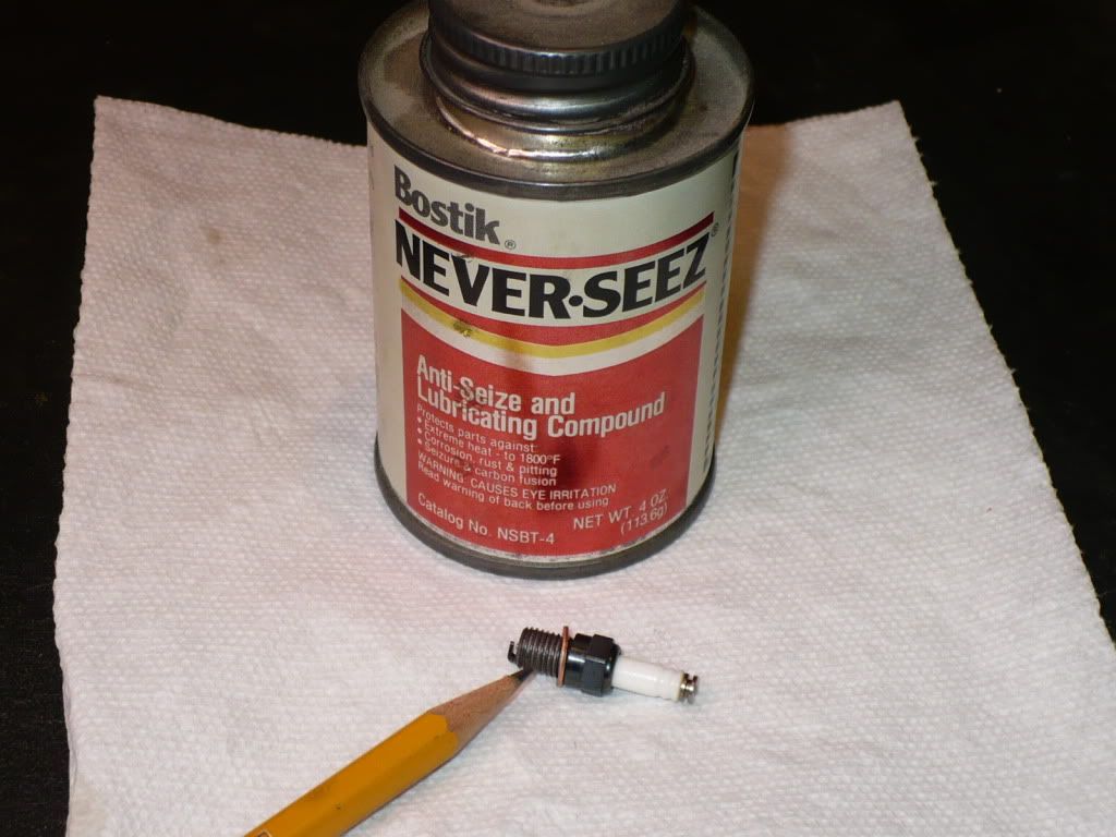
The pencil is pointing to the extensions I made for a #44 tap drill, and a 4-40 tap. An extension for a center drill could be made the same way. I simply drilled out some 7/32" rod and made the assembly permanent by using #609 Loctite. Making my own using this method was much quicker and less expensive than buying a pulley tap.

P1050540.jpg


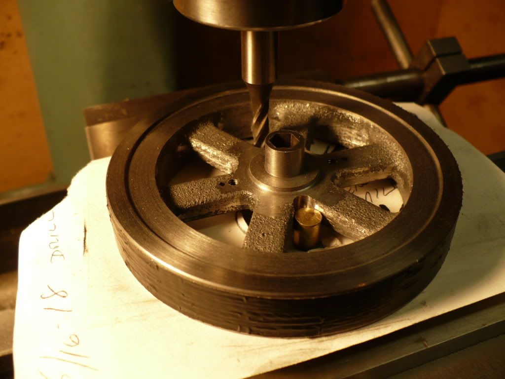
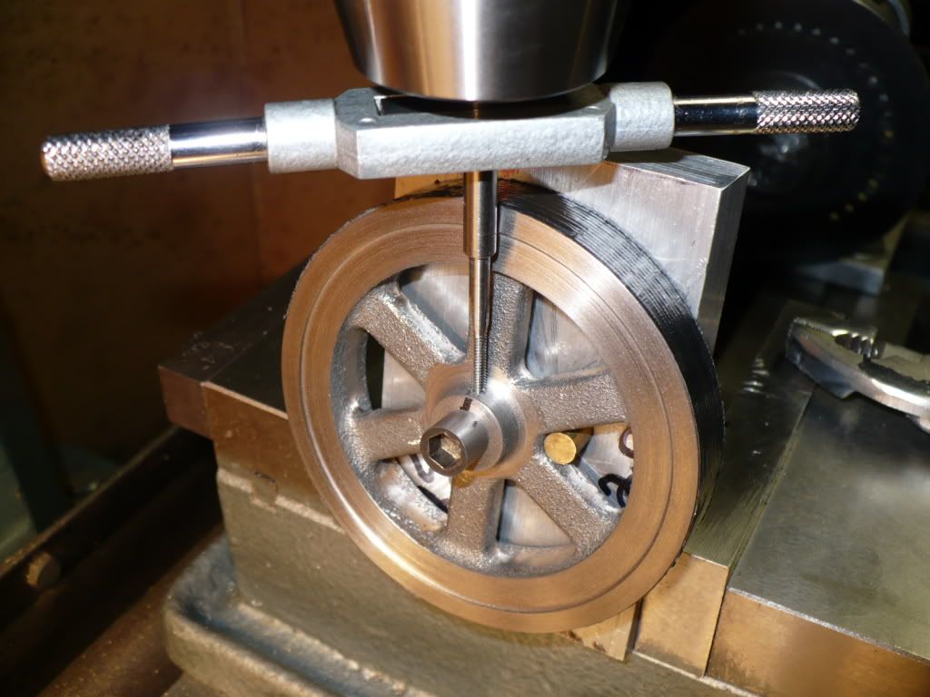
#359 Below I'm using my quick and dirty 'pulley tap'. With the hold down bolt going through the hub it interfered with the drilling. I drilled lightly till I could feel the drill just break through the flywheel hub and touch the bolt, and then I carefully tapped part way in, and finished up by hand tapping at the bench.

P1050541.jpg


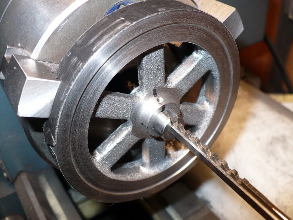
#360 I decided to broach the 1/16" key ways in the lathe. I chuck up a short piece of 1/2" brass round in the tail stock chuck and pushed the broach through by re-setting the tail stock a few times. It only took a few minutes and required less pressure that I normally use on drills over a quarter of an inch in diameter. Shamefully simple!

P1050543.jpg


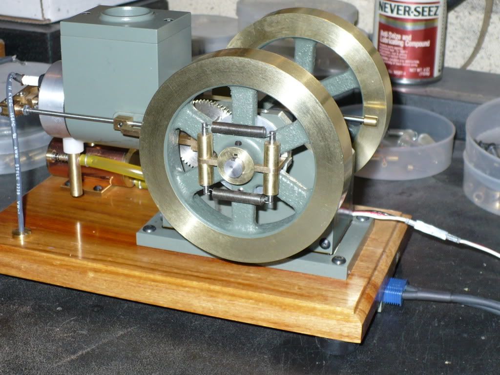
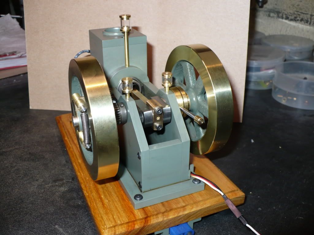
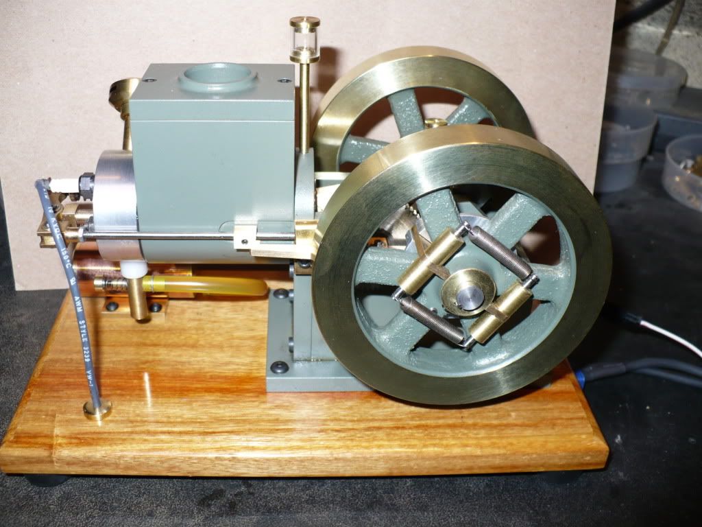
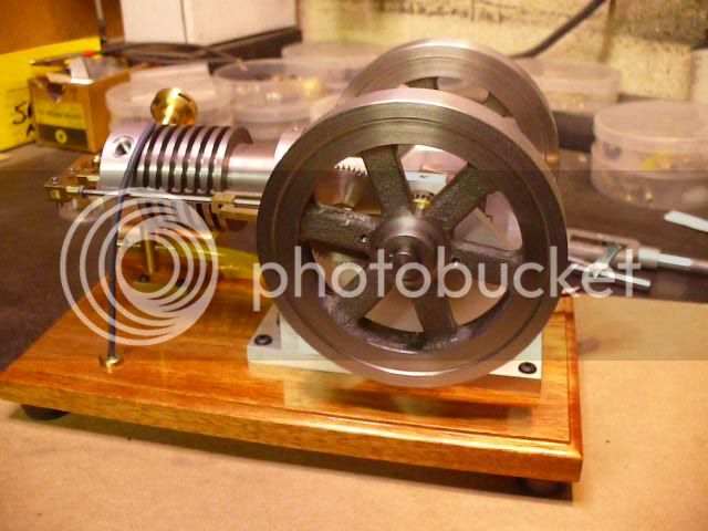
#361 The picture below shows were I'm at with build #2. My spark plugs and clips came in two days after ordering them, so that's what I'll start with tomorrow.

P1050546.jpg


To paint, or not to paint, that is the question..... :noidea:

-MB

 
Hello MB,

It seems every time I have a question you answer it before I can post it! I was going to ask how you used that new set of duMont broaches - whether with an arbor press or some other route and you answered in this recent post. Previously I was going to ask about your ignition setup and of course you went into excellent detail there. Thanks for this great information.

I'll be ordering a set of those broaches - just don't like using set-screws to hold the flywheels.

I know you've been told before on many occasions, but let me say it again - great build series, really a course in how to build model engines. You need to compile this and publish a book - I'll buy at least one!

Best,
Mike
 
Hi Mike, thanks for the compliment. I'm glad to hear that my build thread is helpfull.

My first pair of flywheels could only be broached part way in the mill due to the vise's jaw carriage getting in the way, So I finished up using a 1/2 ton arbor press. The entire job cannot be done in the small arbor press due to a lack of clearance under the ram. Also, the press needed to be hanging over the edge of the bench for broach clearance, or I could have bolted it down and drilled a hole through the bench top.

It was much easier to just use the lathe since it was still set up with outside jaws used to machine the last side of the flywheels.

If you don't have an immediate need for the small broach 'set', you can buy just the 1/16" broach and a 5/16" collard bushing. If the need arises you can always add a bushing or broach.

http://www.shars.com/product_categories/view/2030201/HSS_Standard_Keyway_Broaches_with_Shims

-MB
 
Good news again! Engine #2 is in running order! woohoo1 woohoo1

It took a quite bit of time late last night to get everything adjust to where the engine would run and start on one our two flips of the flywheel. After the engine ran non-stop for about 10 minutes I started to get vapor bubbles in the fuel line at the carburetor. I added a Delrin insulator just like I did on the first engine and it solved the problem.

I had a minor compression leak on the exhaust valve. I couldn't see why it was leaking so I took a very light cut on the valve face and that solved the leak. This might have been caused by the run out on my inexpensive 3/32" collet, who knows, but the second time around using the same collet it worked. I just finished running the engine on a full tank of fuel with only one issue, the needle valve setting is way too sensitive, and will move on its own causing the engine to start faltering till its set back to the good running position. On a full tank of gasoline It ran for about 45 minutes and their was an noticeable increase in compression after the long run just like on build #1.

Later today I'll take the engine apart and start prepping it for a paint job. With the amount of time I have invested on this project, another day or two doesn't matter. :D

-MB
 

Latest posts

Back
Top