MB building Upshur Farm Engines.

Home Model Engine Machinist Forum

Help Support Home Model Engine Machinist Forum:

This site may earn a commission from merchant affiliate links, including eBay, Amazon, and others.
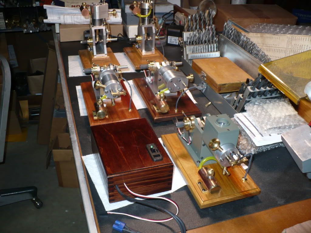
#325 For today's post I'll show how the pig tails with Futaba connectors are attached to the hall sensors, and mounted into the adjustable sensor carrier with epoxy.

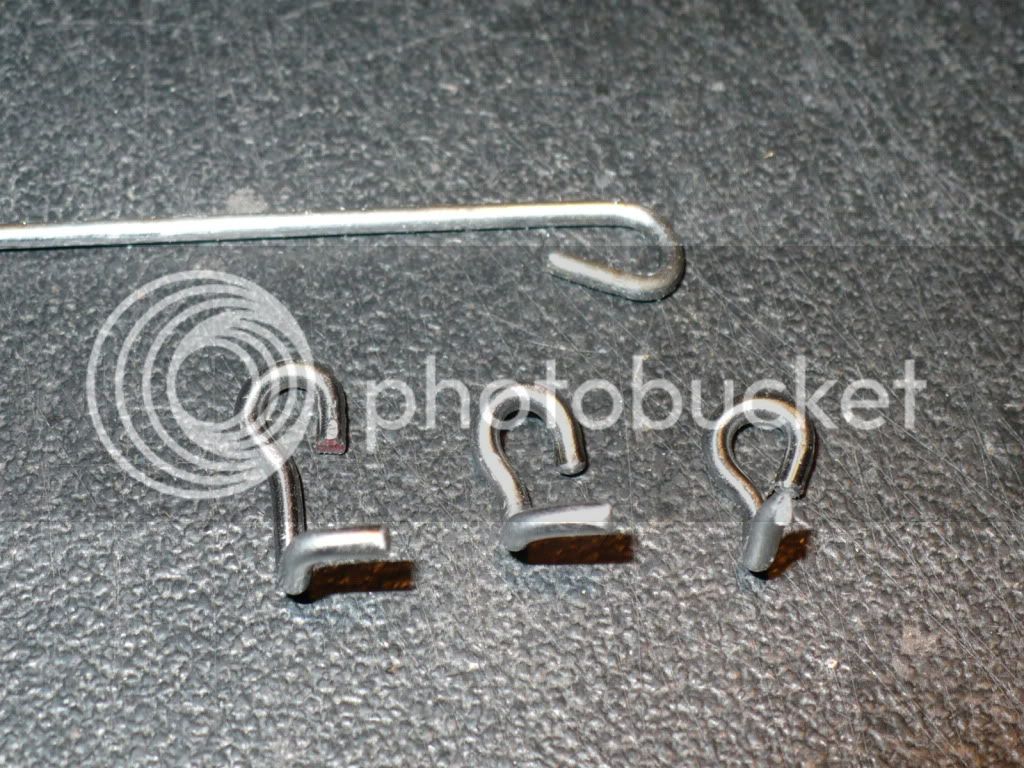
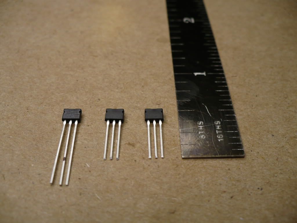
I shortened the prongs on the Hall Sensors by cutting them down to 3/8". This will place the solder joints out side of the carrier allowing for a full support of the prongs inside the added block. The added solder on block was channeled out with an end mill in a previous post.

P1050360.jpg


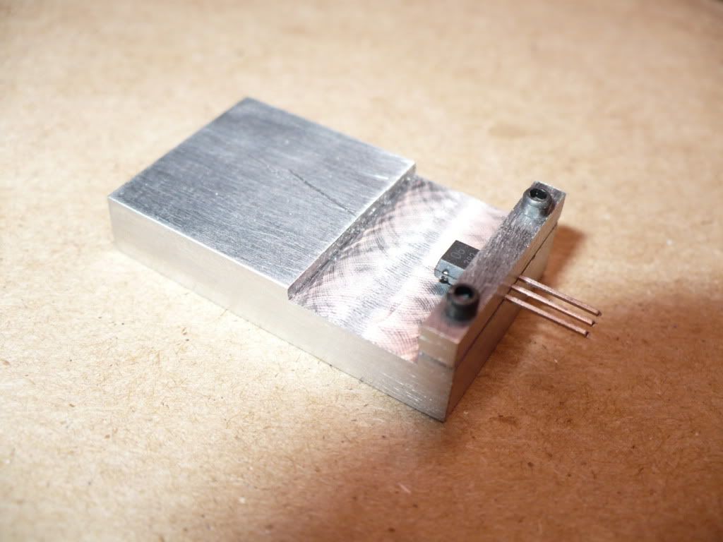
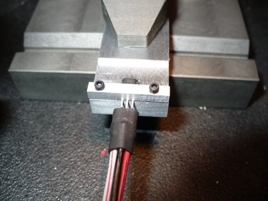
#326 I made a small aluminum combination heat sink and support fixture to minimize the danger of over-heating the sensor, and to hold it steady during the process of soldering on the wires. The hold down bar is .110" x .110" held down with 2x 0-80 cap screws.

P1050369.jpg


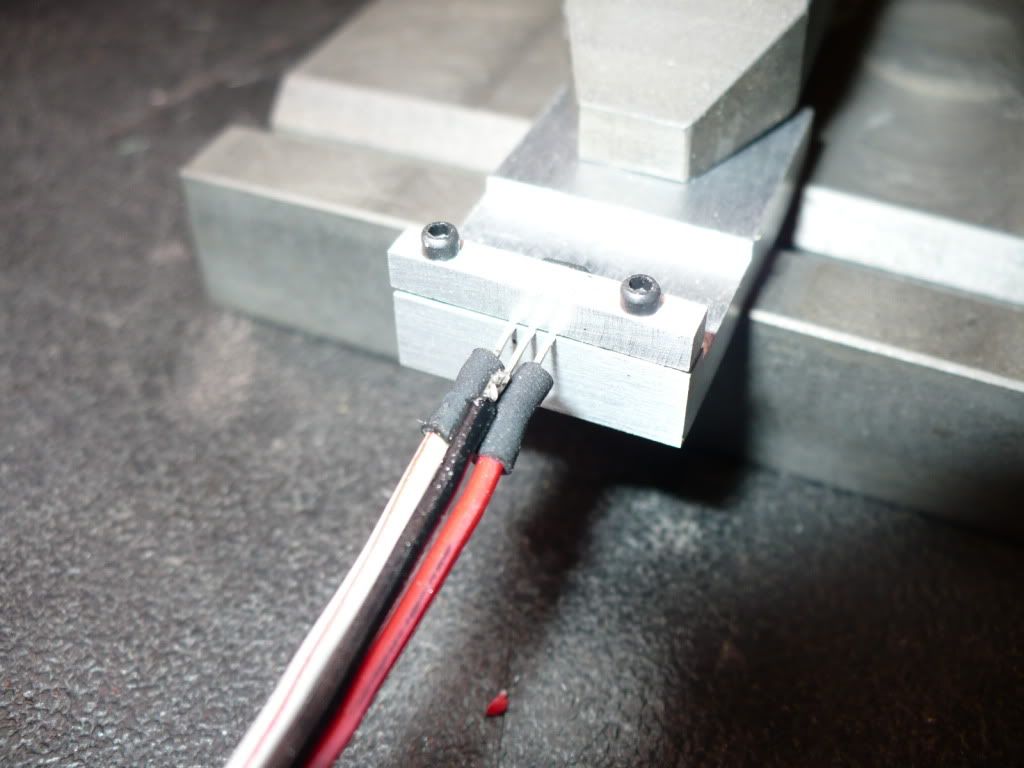
#327 I had to criss-cross the red and black wires to make the proper connections on the hall sensor. I ordered and used 22 ga. wires with the connectors already attached. The wires turned out to be too thick for the close proximity of the prongs on the sensor. It was necessary to solder the center wire on top, and to solder on the outside wires from underneath to have enough clearance. After the soldering was complete I slide two short pieces of shrink tube over the out side solder joints and shrunk them with a lighter. The center solder joint bare and will be protected by the insulation on both side wires.

P1050378.jpg


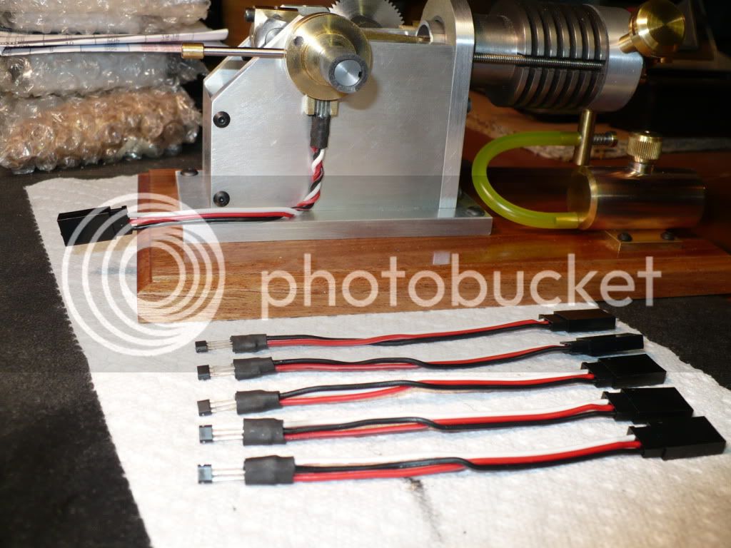
#328 To finish up the assembly a larger and longer piece of shrink tube was slid into place and shrunk to complete the assembly. The shrink tubing should be on the wires prior to soldering. I learned this the hard way on the first one and had to un-solder the connections to get it in place and ready on the wires.

P1050381.jpg


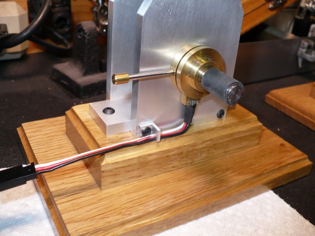
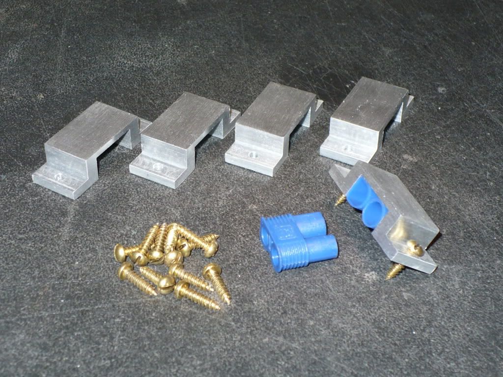
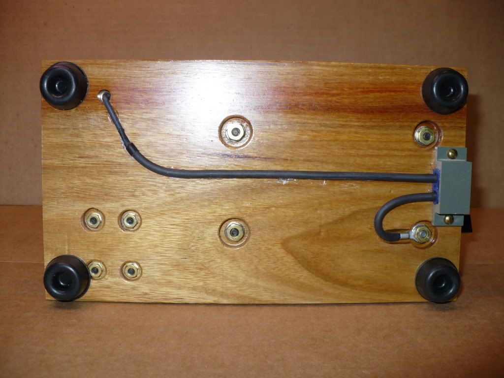
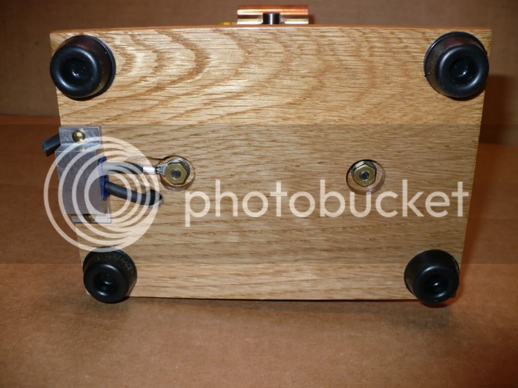
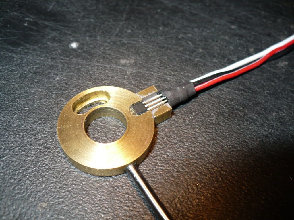
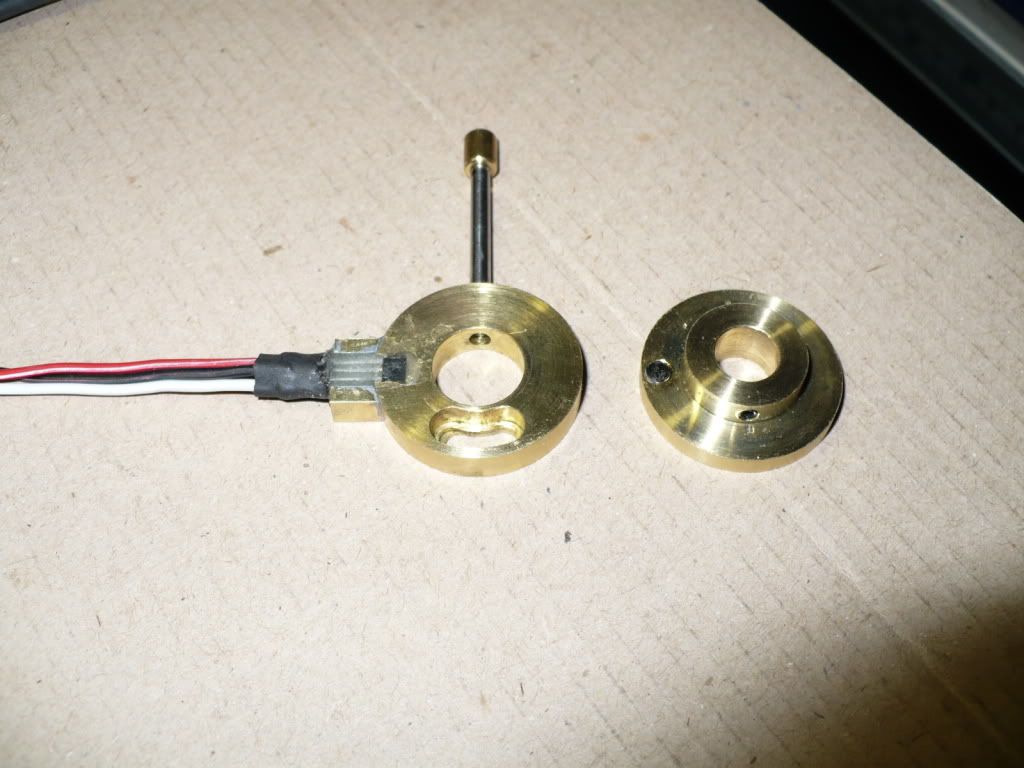
#329 I had previously made up an extra carrier for the sensor, and I also made up an extra sensor assembly in case a sensor fails. This will make the replacement quick and simple. In the picture below you can see one installed. I will need to cover the epoxy and prongs that are showing through with some thin brass shim stock, or some brass colored paint.

P1050389.jpg


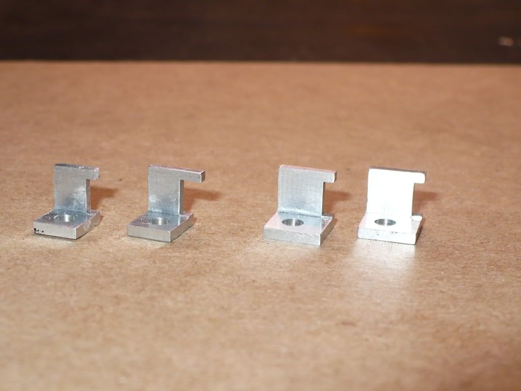
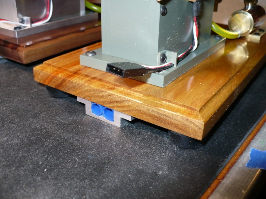
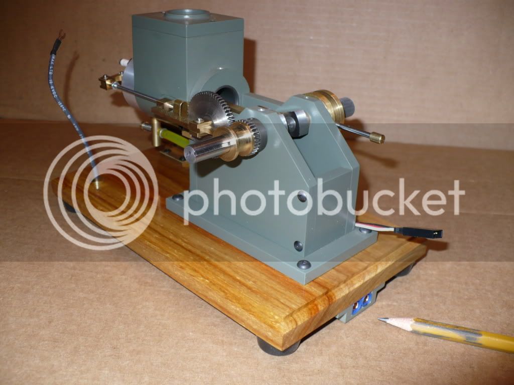
#330 Here's how the assembly looks prior to adding the epoxy. The area around the prongs is wider and deeper than the area around the head of the sensor. This will all be filled with epoxy to encapsulate the prongs and prevent any bending that could lead to sensor failure.

P1050394.jpg


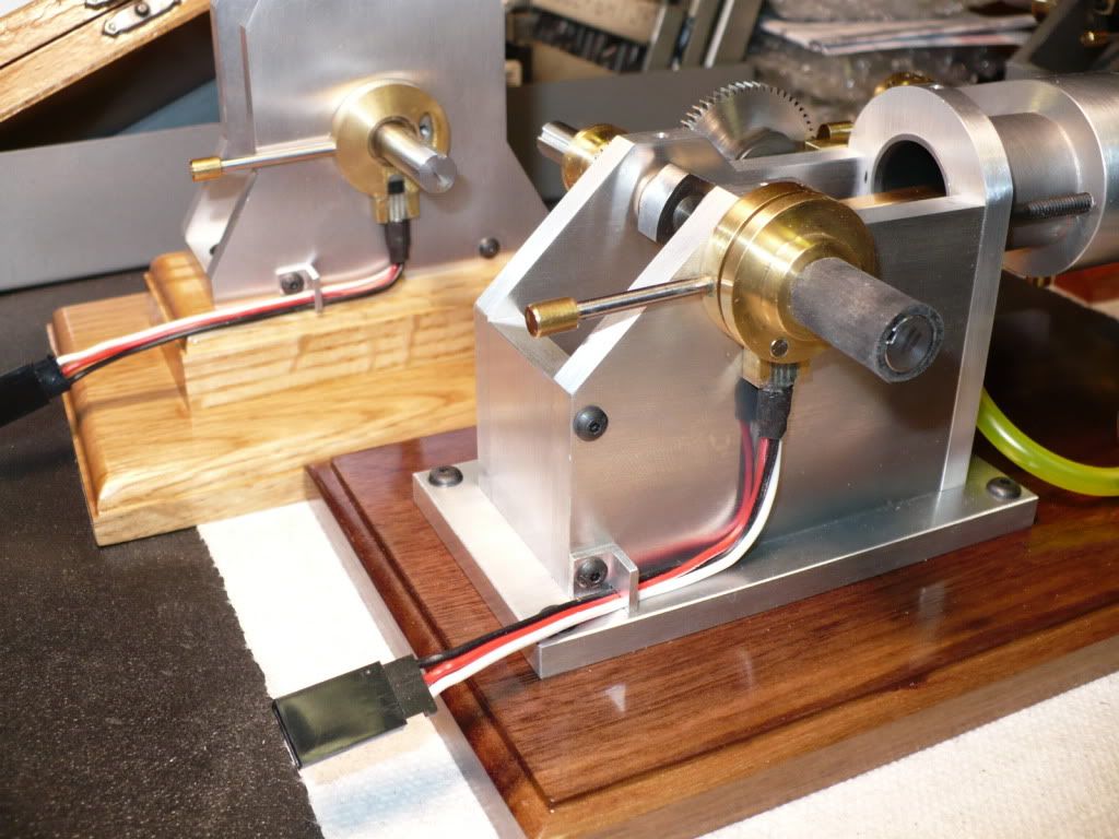
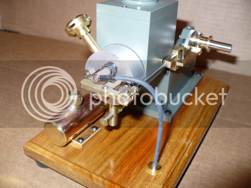
#331 This last picture shows the second hall sensor assembly set in epoxy. I temporarily wired the ignition system to test the sensors and all 6 are firing a plug beautifully! I decided to stop at this point and take a break by posting my progress.

P1050404.jpg


Fire in the hole! Rof} Rof}

-MB
 
Nicely done, MB. I like that combination heat sink and holder. Any special reason for the .110 width of the hold down bar?

Rudy
 
Hello MB,

This has been a great addition to the build progress - I was just wondering how those Hall effect thingies were mounted and you show the entire series!

I'm collecting all your post on this to save as a pdf for my reference when I build the Upshur.

Best,
Mike
 
rudydubya said:
Nicely done, MB. I like that combination heat sink and holder. Any special reason for the .110 width of the hold down bar?

Rudy

Hi Rudy. The fixture was an eye-ball job based on the width of the 0-80 screw head. The dimensions are not critical, just use your own judgment. I measured the width of the hold down bar after machining and presented the information in case anyone wanted to make and use the fixture. I cut my prongs down to 3/8". With the dimension I presented the prongs could be cut much shorter if needed. I went down to the shop and took a few measurements, on my particular installation the bar could have been up to .230" wide, and It would have still allowed enough room to slide the shrink tubing up to the hold down bar. It's important to leave the sensor in the heat sink/fixture during the process of shrinking the tubing. Shrinking takes longer than the soldering, and there's much more time for the heat to migrate towards the head of the sensor and cause damage.
I used a 45W pencil point soldering iron on the leads, and a disposable cigarette lighter for the shrinking.

-MB
 
Hi Metal Butcher,

Just want to say wow, what a great and very well documented build you doing here :bow: :bow: :bow:

Regards Jeroen
 
Hi, MikeA.

Hi, Jeroen.

Thanks For the compliment's. :)

I'm heading back down to the shop.

-MB
 
#332 I finished mounting all of the Hall Sensors in epoxy on the adjustable Sensor Carriers, and mounted the assemblies on the engines. It became apparent that the wire harness needed to be restrained from shifting towards the flywheel while running the engine. I didn't want to drill any additional holes on the frame to secure the wires, so I turned my attention to making a bracket of some sort utilizing the existing screws on the frame.

A formed bracket made from 1/16" wire under one of the screws would be a simple solution and worth trying.
The first one was too big. The second one was too small, and the third one broke. After starting on the fourth one I stopped. It was time to re-think a mounting bracket before wasting any more time on the bent wire idea!


P1050409.jpg


#333 The best solution would be to machine up a bracket. It would have to be as small as possible, and mount under the existing screw towards the back of the frame plate, and also made of aluminum so it would blend in somewhat with the frame plate. After taking measurements, It became apparent that the two vertical versions would need slightly different brackets due to the different routed edge's on the wood bases. But, the three horizontal versions could all use the same bracket. I drew up my idea of how the brackets would look and machined them up.

The two on the left are for the two vertical versions. The bracket on the far left is for the square edge routed base, and the bracket on the right side of the pair has a longer pin since the routed edge is rounded over, and the wires could slip out from under the bracket.

The two on the right are for the three horizontal versions. A third one (not shown) was painted 'Trout Green' and was wet when I took these picture. Other than the paint, all three are identical.

P1050422.jpg


#334 The engine in the back ground has the longer pin on the bracket to meet with the rounded over edge on the wood base. And the one in the front is one of three identical ones used on the horizontal versions.

P1050426.jpg


#335 The engine in the picture below is the vertical version with a square routed edge on the wood base, and uses a bracket with a shorter pin.

Its hard to believe that these five simple brackets took five hours from conception to final installation!

P1050429.jpg


#336 The Tygon fuel line I ordered has an I.D. of .113", and fits well on the .125" fuel tank and carburetor nipples. I wanted to be assured that the connections would be leak free since I'll be dealing with highly flammable gasoline. I tossed all sorts of ideas around before settling on a simple solution. By adding a single coil of spring with a slightly small I.D. than the O.D. of the tubing, it would compress the tubing slightly making for a much tighter connection.

I found the perfect size spring and cut off single loops. The loops are installed over the tubing prior to pressing it on the nipples. They add about .010" compression, making a very positive seal between the tubing and the nipples.

P1050437.jpg


#337 Here's how the 'hose clamps' look installed. Clean, simple, and effective. I like it! :)

P1050442.jpg


The florescent yellow color of the fuel line looks just as bright as it does in the picture. Its the right stuff, but...yuck! :rant:

-MB
 
MB,

These engines are very inspiring. I am currently working on my first engine (Elmer's #42) and am amazed at the pace that you are moving forward. The surface finish on your parts is excellent. What coating did you use on the copper section of your fuel tanks?

Please continue to post the detailed process pictures!

-Nathan
 
Hi MB
That tube is a bit strong but nothing can detract from the class of your motors
A fan :)
 
nds213 said:
MB,

These engines are very inspiring. I am currently working on my first engine (Elmer's #42) and am amazed at the pace that you are moving forward. The surface finish on your parts is excellent. What coating did you use on the copper section of your fuel tanks?

Please continue to post the detailed process pictures!

-Nathan

Thanks Nathan!

I didn't use any coating on the fuel tanks, its a sanded surface that I polished lightly with Flitz metal polish. I usually leave a surface with a sand papered finish, or a machined finish to control the glare. If I want to slow down the tarnishing, I use a 'poly" type of paint sealant used on car finishes.

http://www.flitz.com/p-16-flitz-polish-paste.aspx

http://www.acehardware.com/product/index.jsp?productId=1420358&clickid=prod_cs

-MB
 
metalmad said:
Hi MB
That tube is a bit strong but nothing can detract from the class of your motors
A fan :)

Thanks for the compliment, and I'm glad that your enjoying my thread!

If I can find a good 'clear' substitute for the yellow Tygon tubing it will only take me a few minutes per engine to change it out.

-MB
 
MB,

Is there a way that you could use a hard line from PM Research for the fuel line?

-Nathan
 
The wire clips and fuel clamps are nice, Rick. I never would have though of cutting up a spring for hose clamps. They look very clean.
If you would rather have a different color for the fuel line, an RC shop will have natural silicone line. It is not colored, looks kind of clear.
 
nds213 said:
MB,

Is there a way that you could use a hard line from PM Research for the fuel line?

-Nathan

Hi Nathan. Using copper tubing is possible, and I have seen it done. However in my case it would be difficult since the carburators and fuel tanks are all finished up, and as drawn on the plans.

I would rather use clear flexible fuel line for ease of assembly. And if I need to take a head off, disconnecting the fuel line is very easy. If I want to experiment with switching carburetors around, it would be difficult since each engine is slightly different with fuel line length and tank location.

-MB
 
Deanofid said:
The wire clips and fuel clamps are nice, Rick. I never would have though of cutting up a spring for hose clamps. They look very clean.
If you would rather have a different color for the fuel line, an RC shop will have natural silicone line. It is not colored, looks kind of clear.

Hi Dean. Thanks for the tip. I am going to a hobby shop tomorrow, and will take a look at what they have. The fittings on the carbs and fuel tanks are .125" O.D.. So I better bring a piece 1/8' rod allong for a test fit before buying.

-MB
 
Unfortunately silicon tubing is not compatable with gasoline. I swells up after a few hours of exposure.
Small engine repair shops usually have a clear that is compatable with gasoline and will sell you a foot or so.
Locally, I have bought clear in the chain saw section at Ace Hardware. They sell it by the foot. It does not swell, but gets hard after a few months of exposure to gasoline so has to be replaced if you take it often. It is only about 60 or 70 cents per foot, so not a big deal. They had three sizes when I was there last and the middle size is probably right for 1/8 inch barbs.
Gail in NM
 
Hi Gail, thanks for reminding me about the silicone in-compatibility with gasoline. I think the silicone works with air plane fuel though. I'm going to the hobby shop tomorrow anyway, so I'll ask just in-case they have a tubing that's compatible with gasoline.

I remember disusing this subject on a thread a while back...somewere... but just like my memory it's long lost. :D

Tygon was the right stuff, that's why I bought it. Too bad its an ugly florescent yellow. Looks like a cheap fishing lure. Rof}

-MB
 
#338 I made 5 simple aluminum brackets to hold the female EC3 connectors solidly to the under side of the bases. The brackets were attached with 2 wood screws. I snapped the head off of the second one and afterward pre-drilled for the screws with a small bit held in a pin chuck. Fortunately the was enough of the screw sticking out of the wood to get a good grip on it with a pair of pliers. The brackets are a tight fit with only .020" air space between the bottom of the brackets and the bench top. Thicker rubber feet on the four corner would have helped, but I couldn't find any.

P1050448.jpg


#339 The brackets were styled to match the rest of the build. This picture shows how a miss-matched part looks. It needs a coat of 'Trout Green' to make it blend in!

The hard part will be to solder and assemble all of the E-flite EC3 connectors, and to rout and attach all the wires under the bases. After that the next step will be to assemble the battery powered remote ignition box. All these pesky little details take a lot of thought and time to work out and assemble.

P1050451.jpg


-MB
 
#340 I spent the last few days assembling the E-flight connectors, and the wiring on the underside of the engines. All five are done with the exception of soldering on the spark plug clips. I only ordered one along with the basic CDI system to see if they would be satisfactory. and forgot all about ordering the rest. With luck my order should arrive in a few days.

I tacked the wires in place with a super glue jell. A fine bead of clear silicone will be added on both sides of each wire to make them more secure.

P1050456.jpg


#341 Here's how an assembled connector looks. After the connector and wiring was in place satisfactorily, I removed the connector bracket and coated the inside of the bracket with clear silicone and installed it back in place with the two wood screws. This will keep the engine mounted female plug from shifting while plugging in the wired male plug from the ignition box.

P1050457.jpg


#342 Here's a picture of how the spark plug clip looks installed and clipped on a spark plug. Since the clip from S/S works just fine I ordered more to complete the wiring of all five engines.

P1050460.jpg


#343 The two vertical versions were much easier to wire. The wires going up to the spark plug are on the same side as the Hall sensor Futaba plugs, and the hot and ground EC3 plugs.

P1050462.jpg


#344 I also managed to assemble the remote CDI ignition box. I used a inexpensive wood box purchased on e-Bay. It was already stained, so all I needed to do was put on a few coats of sealer and polyurethane finish. I mounted the power switch on the lid of the box for easy access regardless of the boxes position. On the left side of the switch is a clear LED that glows bright green when the ignition is powered up.

I used the basic $55 system from S/S.

http://www.cncengines.com/ic.html

P1050463.jpg


#345 When I tried to plug in the switch I found out that the Hong Kong seller had sent me one wired with RJ plugs instead of the Futaba that I ordered. Since the purchase was 4-5 months ago, and ordering a replacement would take too long, I cut off the plugs and soldered the connections.

When the ignition box is not in use, the wires can be coiled up and stored inside the box.

P1050466.jpg


#346 To use the ignition box, the wires are uncoiled and slipped into two slots cut into the lower half of the box just below the lid.

P1050468.jpg


#347 With the wires out and secured in the notches the lid can be closed. I need to find and buy a small latch to secure the lid.

P1050470.jpg


#348 Here's a group picture of my progress to date. There's only a few minor details left to finish, and then I'll start machining the flywheels.

P1050474.jpg


-MB


Very nice "Family Portrait" there MB. ;D ;D

You're sure doing a bang up job on this. :bow: :bow:


Ron
 

Latest posts

Back
Top