MB building Upshur Farm Engines.

Home Model Engine Machinist Forum

Help Support Home Model Engine Machinist Forum:

This site may earn a commission from merchant affiliate links, including eBay, Amazon, and others.
I like the red, too! Glad you got your pics back, Rick.
 
#383 Today I finished up assembling Engine #4, the Vertical F-Head with optional hit-n-miss governor. As usual I had a tough time with those pesky little E-clips, and spent a good amount of time chasing down the ones that flew away and ended up on the floor! I wasn't very fond of the red color last year, but its starting to look good. Its amazing how the full screen close-up shots show off dust that I cant see with my tired old eyes.

The next step is to see if I can get it to run. Maybe I'll try tomorrow, this way I can enjoy looking it over without the mess that the oiling will cause. :D

P1050616.jpg

#384
P1050618.jpg

#385
P1050621.jpg

#386
P1050623.jpg

#387
P1050625.jpg

#388
P1050626.jpg

#389
P1050627.jpg

#390
P1050630.jpg

#391
P1050632.jpg

#392
P1050635.jpg


One more engine left to assemble

-MB
 

Your engines are beautiful MB!

I like the different configurations.
 
Looking great MB
Pete
 
Lovely work, MB. What are you going to do to top this series?

Chuck
 
Hello MB,

Magnificent work. I have thoroughly enjoyed following your build(s) and always look forward to your next post. I hope the remaining assembly and initial starting and sorting out goes as smoothly as possible.

Thank you for taking the time and effort to share this with us. I certainly appreciate your efforts.

Kind regards,
Mike

P.S. Thanks for getting your pictures back on-line. I was kicking myself for not copying some of them a putting them in a folder when I saw that they were gone a few days back. :wall:
 
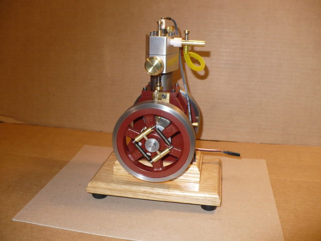
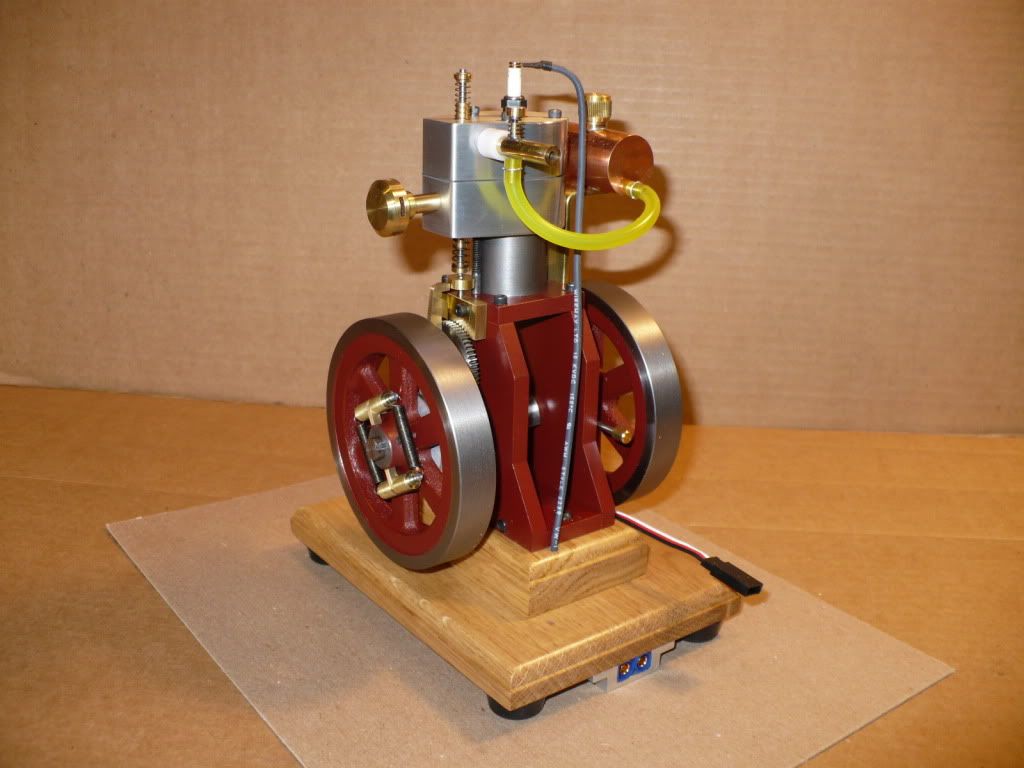
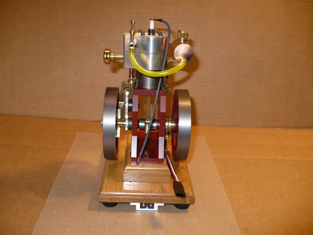
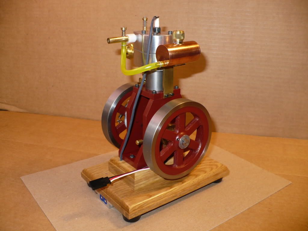
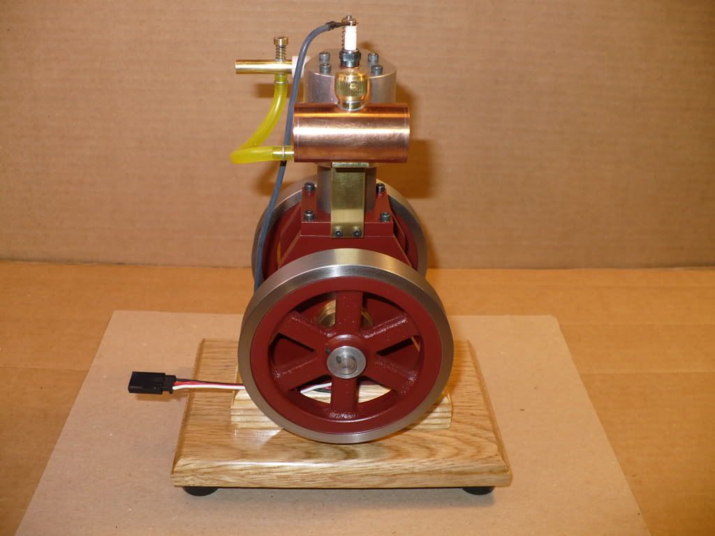
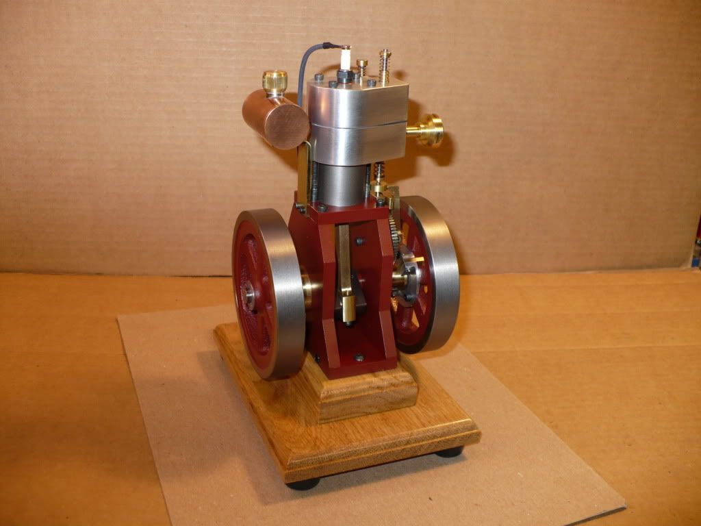
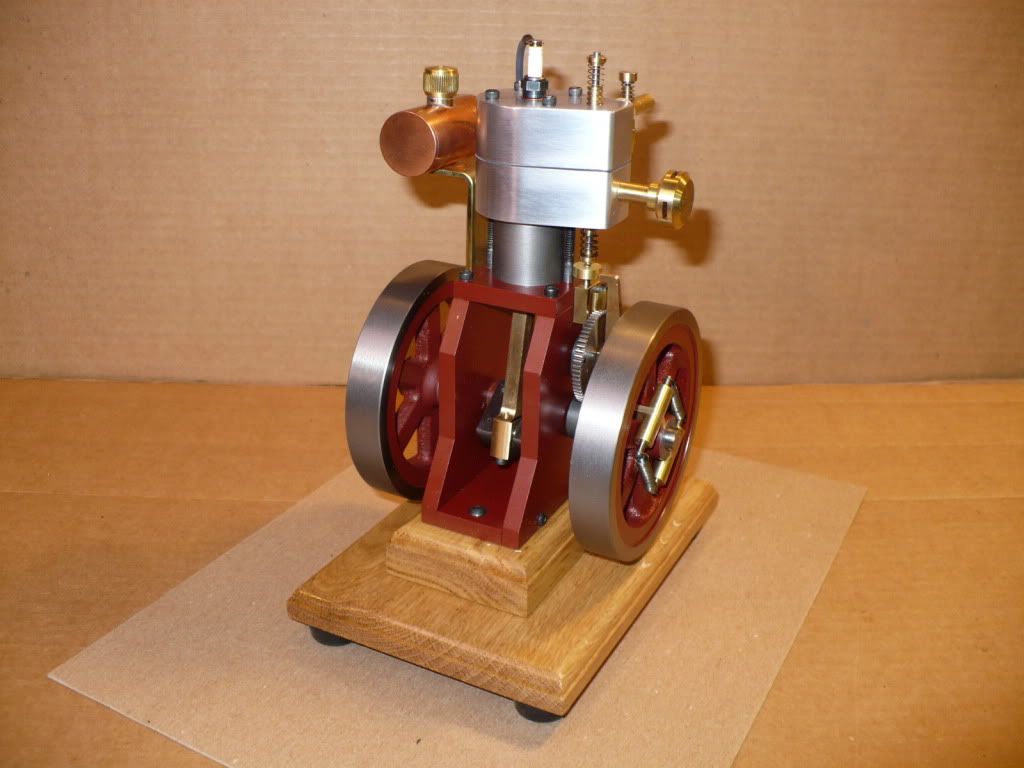
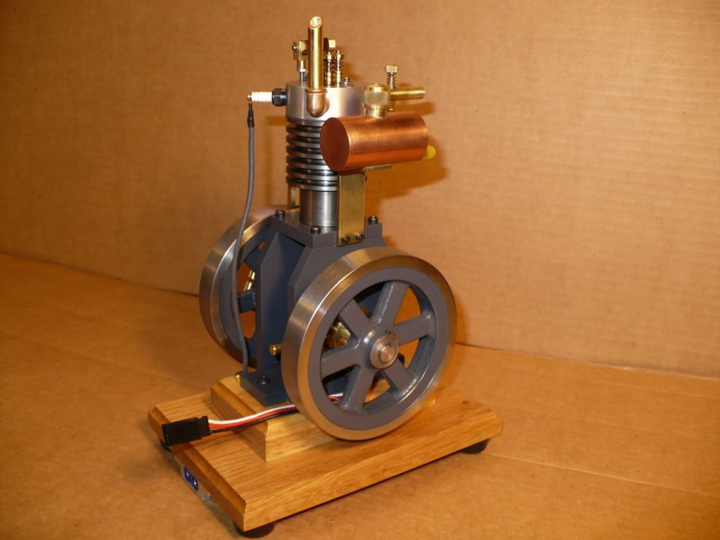
#393 I posted this same information earlier on my #3 video thread. I copyied & pasted it here on my build thread, where it may benefit a future builder.

I was having a problem with multiple sensor failure on engine #4, and solved the problem by insulating the entire sensor and its prongs with shrink tubing. It worked! The engine is starting and running great.

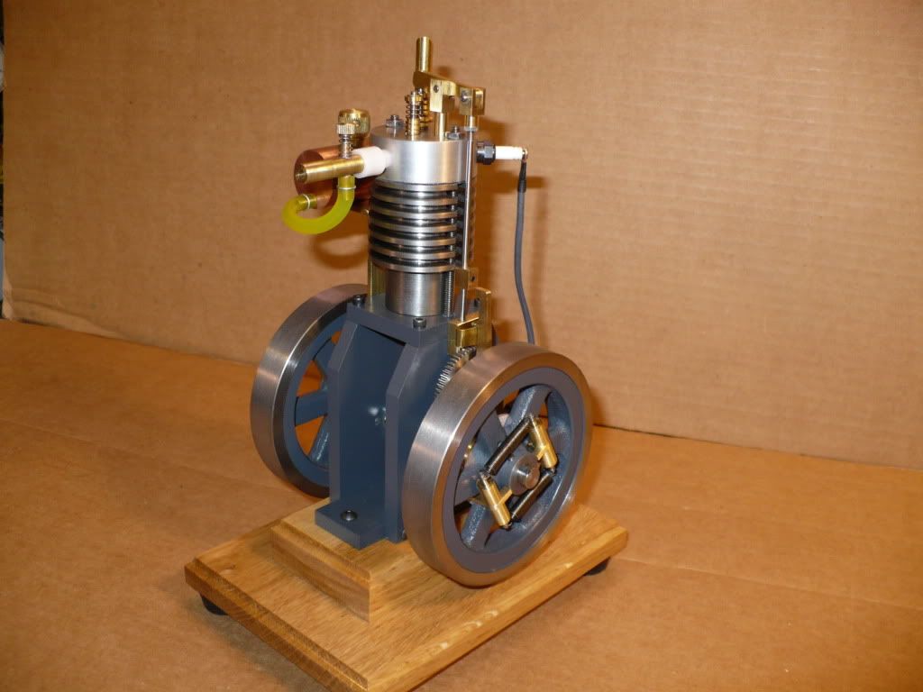
I made the same insulation change on this engine (#3) and the erratic running and shutting down behavior it was displaying for no apparent reason has gone away. I started it several times this morning and ran it without any issues.

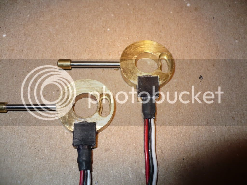
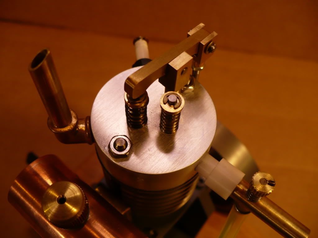
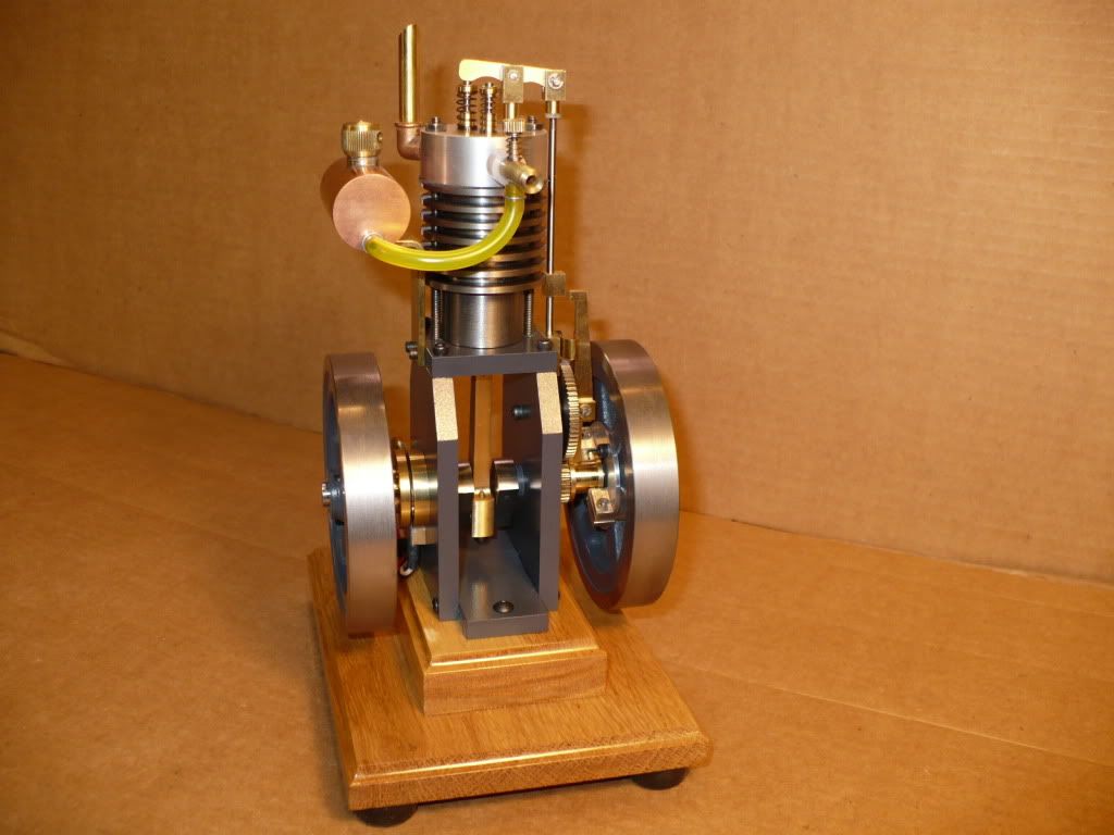
The lesson learned with this experience is to insulate from the solder joints all the way up-and-over the entire sensor chip, past the top by 1/16" or slightly more, and seal the open end with a silicone sealant. Once it sets up you can mount the sealed sensor in any type of mount including metal, and mount it in place using whatever glue you like with out any problem.

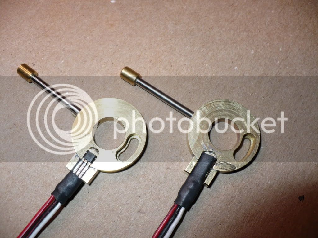
The carrier on the left shows the potentially flawed way I originally set up the sensors and filled the gaps with a 2-part epoxy. This is the most likely cause of the sensor failures I encountered. On the right is the new method I used to completely insulate the sensor before it was glued in place.

So far, two engines have this improvement and continue to run with out any of the problems I encountered with the original mounting method.

P1050637.jpg


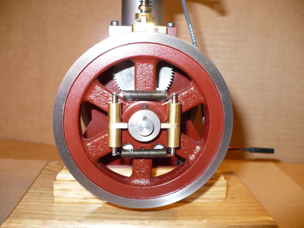
#394 I used super glue jell to 'pot' the insulated sensor, and added a 3/8" x 3/8" x .030" piece of plastic to hold it in place while the glue set up. Using a thin piece of plastic over the top made the assembly a little easier and added another layer of insulation.

P1050641.jpg


-MB
 
#395 Engine #5, The Vertical Air Cooled Hit-N-Miss version is fully assembled and ready for its maiden run! It took me the better part of the day. The problem being build #3 & #4 sitting on my other bench gassed up and ready to run. They have been a major a distraction all day. I fire one up and let it run, hook up the CDI to the other one and let it run, open the windows in the shop and go up to let it air out a bit, and repeat the cycle after adding a part or two to build #5. :Doh:
P1050660.jpg

#396
P1050666.jpg

#397
P1050667.jpg

#398
P1050668.jpg

#399
P1050671.jpg

#400
P1050674.jpg

#401
P1050675.jpg

#402
P1050677.jpg

#403
P1050678.jpg

#404
P1050680.jpg


-MB
 
I have been following along from the start. Now that you are coming to a close here I just wanted to thank you for posting the pics and all i can say is..

Outstanding!!!!!!!!!!!!!!!!!!!!!!!!!!!!!!!!
 
Another full on beauty, Rick. You sure know how to make a great looking engine look even better
with a bit of wood work. You have a good eye for esthetics to go along with your machining skills.

Dean
 
I have to say you have done a super job :bow: :bow:
And have a beautiful set of engines to take pride in :bow: :bow:
I don't know if I could pick a favorite they all are so beautiful!!!!!!!
 
I think the vertical is my favorite. Very clean lines, nice colors, great machine work, altogether very pleasing. What are the dimensions of the clevis on the end of the push rod that attaches to the rocker arm? Also, what size pin did you use? I'm thinking of using your rocker arm design for my radial compressed air engine, but might have to scale it down some.

Chuck
 
cfellows said:
I think the vertical is my favorite. Very clean lines, nice colors, great machine work, altogether very pleasing. What are the dimensions of the clevis on the end of the push rod that attaches to the rocker arm? Also, what size pin did you use? I'm thinking of using your rocker arm design for my radial compressed air engine, but might have to scale it down some.

Chuck

Thanks Chuck! The clevis was made from 1/4 x 1/4" square brass bar stock. I set up a 2" long piece sticking out the side of my mill vise and used a 1/8" slitting saw to cut the 1/4" deep slot for the 1/8" thick rocker arm. I cut it off a 1/2" long and turned the round boss .150 long x .200" diameter using a square collet in the lathe. I drilled for the 3/32" push rod (it gets threaded 3-48) from the boss end all the way through to the slot and tapped it 3-48. I drilled and reamed a 3/32" hole for the pivot pin centered and 1/8" from the slotted end of the clevis.

The pivot pin and the threaded push rod are 3/32" drill rod. The pivot pin was grooved on both ends .020 wide x .010" deep for E-clips. The diameter of the groove should be .074". I don't have the ability to measure a thin groove like this, so I use a marker pen on the pivot pin and advance the groove cutter till it touches, zero out my indicator and go in .010". After I check the fit with an E-Clip I make a minor adjustment to the depth of cut on the next groove if needed.

Enco has the 3/32" E-Clips, E-9 is the industry # and the order # is 325-2834.

-MB

 
Hello MB,

Yet another success! Must be getting a bit boring for you (NOT!)

I have one question - is there anyway to reduce the shaking around when these are in the H&M mode? Any way to improve the balance perhaps?

Best,
Mike
p.s. - I'm still plugging along on my single version of the Upshur, (although I have several engines worth of 'spare parts'!)
 
MikeA said:
Hello MB,

Yet another success! Must be getting a bit boring for you (NOT!)

I have one question - is there anyway to reduce the shaking around when these are in the H&M mode? Any way to improve the balance perhaps?

Best,
Mike
p.s. - I'm still plugging along on my single version of the Upshur, (although I have several engines worth of 'spare parts'!)

Hi Mike! Thanks for the compliment. My engines have a jump that makes a hammering sound on a bench top. There are a few things that might help to reduce this.

A lighter piston rod made of aluminum.
Counter weights on the crank webs.
Counter weights on the flywheels.
A larger, thicker, and heavier wood base, maybe a painted steel base?

It only takes a little finger pressure to stop it from hammering on the bench, but its a nuisance issue worth addressing.

-MB
 
I may have found the answer to a hit and miss engine "jumping around" by accident. I mounted my engine on a peice of wooden 2 x 8" spruce wood, (see avatar) and routed a bunch of grooves in the underside of the wood for the electrical wiring. After the wiring was all tucked up in place, I filled the grooves with slilcone from a tube with my caulking gun. I let it set up overnight to solidify, and the next morning I found that the silicone was about 1/32" "proud" of the wooden base. That bit of silicone keeps everything very stable when the engine is running. It has enough "give' to soak up any vibration from the engine, and a high enough co-efficient of friction to keep the board from sliding around when the engine runs.----Brian
 
Hello MB, Ray and Brian,

Please understand I'm proceeding a bit 'blind' on this but I think Rick put his finger on it with the need for some balancing of the flywheel vs. the reciprocating mass (piston, gudgeon pin, small end of the con rod and part of the balance). I've noted on the plans for the Farm Boy he takes a cut for balance out of the side of the flywheel opposite the crank throw and am wondering if that would be any help.

I'm thinking of drilling perhaps 4 - 6 holes on the inside of the flywheels at the perimeter. This is strictly SWAG at best.

I like the idea of the silicon on the base, may try that as well - it can't hurt! :D

Best,
Mike
 
Something that works well for me is Non Slip shelf liner for the kitchen shelves. It is about 3/32 inch thick (2mm) and has a high coefficient of friction. It is soft and dampens vibrations very well. Just cut a piece a little larger than the base of the engine and place it under the engine. It really quiets the mechanical engine noise down from the vibrations transmitted through the base to a solid surface such as a table as well as keeping the engine from walking around.

It is also very useful to have pieces to set on the mill table or lathe bench to set things like measuring tools on. It protects the tools from the hard surface and keeps them from "walking" arround if there are vibrations. Protects the bench top or machine tool paint from scratches and dings too when you set a cutting tool down.

I first found this material at a RV supply where it was sold to keep dishes from rattling around in the cabinet when driving. That was years ago. Now you can find it in the shelf paper section of supermarkets. It is inexpensive so you can just replace it when it gets dirty.

Gail in NM

Non Slip.jpg
 

Latest posts

Back
Top