
You are using an out of date browser. It may not display this or other websites correctly.
You should upgrade or use an alternative browser.
You should upgrade or use an alternative browser.
MB building Upshur Farm Engines.
- Thread starter Metal Butcher
- Start date


Help Support Home Model Engine Machinist Forum:
This site may earn a commission from merchant affiliate
links, including eBay, Amazon, and others.
- Joined
- Dec 28, 2008
- Messages
- 1,731
- Reaction score
- 9
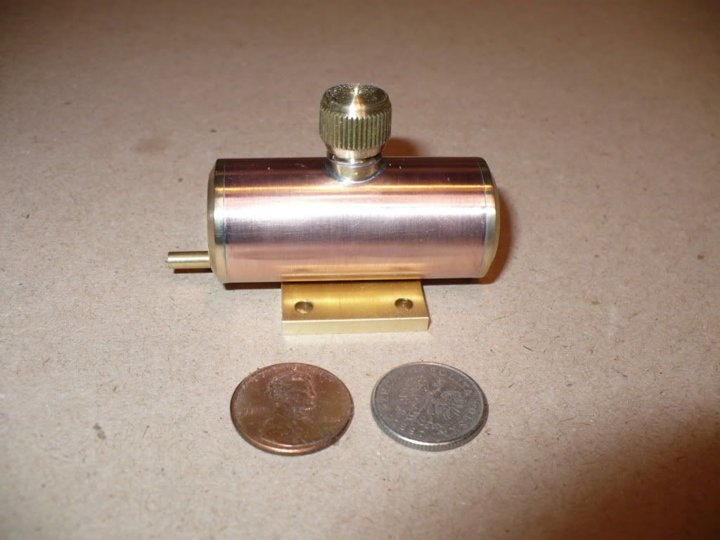
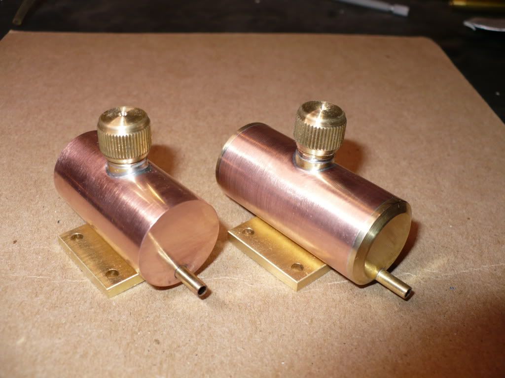
#290 for that last several days I have been working on ideas for the gas tank construction. I made parts from aluminum, brass, and copper. Most of the test parts were not satisfactory and ended up in my recycle bins. Below is a picture of the semi finished parts and a temporarily assembled tank to illustrate what I decided will be used. I would have preferred using an all brass construction, but it turned out that I didn't have the appropriate tubing on hand. Placing an order online would have been a bit cost prohibitive and would have added another delay to the project.
The end caps need to be drilled for fuel line nipple. Since the plans do not show how to mount the tanks on the vertical versions, or how to mount the tanks on the horizontal versions I need to come up with some ideas of how to do this.
It seems that soldering everything together will be tricky at best. I wonder if Loctite would hold up to gasoline, it would make the assembling trouble free.
#291 The nipple for the gas cap was threaded 3/8-24, and the section that goes through the tank was reduced to 5/16". To make the transition to the copper pipe a 3/8" brass rod was drilled 5/16", a radius was added with an end mill, and the bushing was cut off on the lathe. Using the bushing makes the nipple self aligning and gives a neat look to the assembly. The gas caps were made by modifying the profile on standard drain caps found on household water shut off valves.
"Don't worry "Honey" I'll have the water back on in a few days." Rof}
#292 The assembly looks clean simple and neat. I'll try to keep it that way by applying the solder from the inside, and before I add the end caps.
When I go shopping tomorrow, I'll stop at Home Depot. :idea:
-MB
- Joined
- Dec 28, 2008
- Messages
- 1,731
- Reaction score
- 9
#293 For today's post I'll show the progress made over the last three days. Due to the center line height of the needle valve on the carburetor, the tanks for the horizontal versions (3 engines) need to be mounted almost flat on a wooden mounting base. This limited my choices. Rather than strapping the tanks directly to the wood I decided to make brass mounting plates. Using a cradle with the tank strapped on would certainly look much better. But, I decided on simplicity to stay in line with the spirit of Hamilton's design.
Here I'm drilling the 4-40 clearance holes in the 1/8" thick mounting plates.
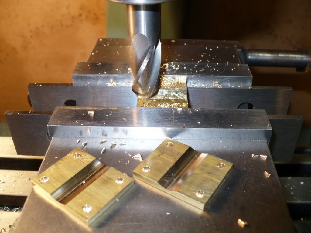
#294 To make the soldering easier I milled a line-up trough on the plates. The diameter of the tanks is 7/8", and the ball end mill I used is only 5/8". It should work to line up the assembly. I would have preferred to use the proper size end mill but I have to use what I have on hand and make it work.
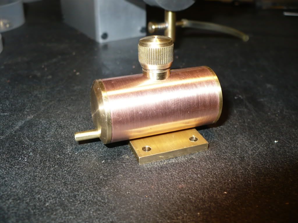
#295 Below is a picture of a temporary assembly to see how the tanks will look. In addition to keeping the tanks low It will be necessary to make a base plate for all three horizontal versions to hike-up them up. Lately it seems that every time I make a part, it creates a need for another part.
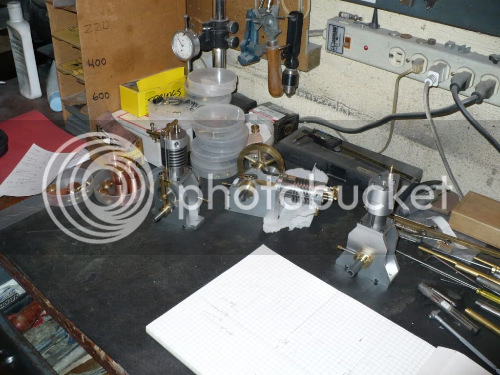
#296 This is a picture of the clutter and confusion I have on my work bench.
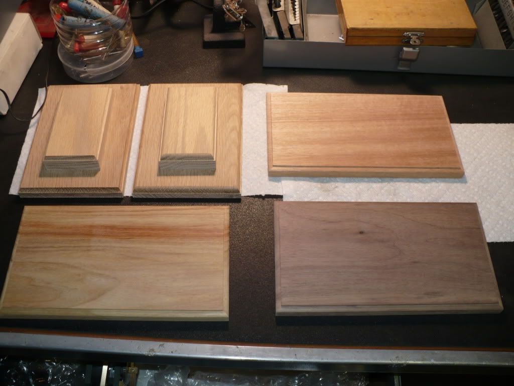
#297 Cutting the wood for bases is not my 'cup of tea'. Usually it chips out when cut and routed, or it ends up with burn marks. I got lucky this time around. The two, two-piece bases in the upper left corner are for the vertical versions. On the horizontal versions the center-line of the crank is 2" up from the base, and on the vertical versions it only 1-1/4". This means that the addition of a 3/4" sub-base is required due to the 3-1/2" fly wheel diameter. Using a slab of aluminum would be odd to say the least so I used 3/4" wood (oak) for the base and sub-base instead.
The three bases for the horizontal versions are Mahogony, Walnut, and Canary wood in a clockwise rotation.
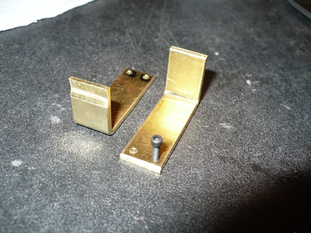
#298 On the Upshur web site the one vertical version shows the fuel tank mounted to a head bolt with a single strap. To avoid the need to remove the fuel tank if the head assembly needs to come off, I decided to make a separate bracket. Again, to keep in line with the spirit of the simple design I made the appropriate mounting bracket. It bolts to the cylinder base with two 2-56 screws, and I added the same milled line-up trough to simplify the assembly.
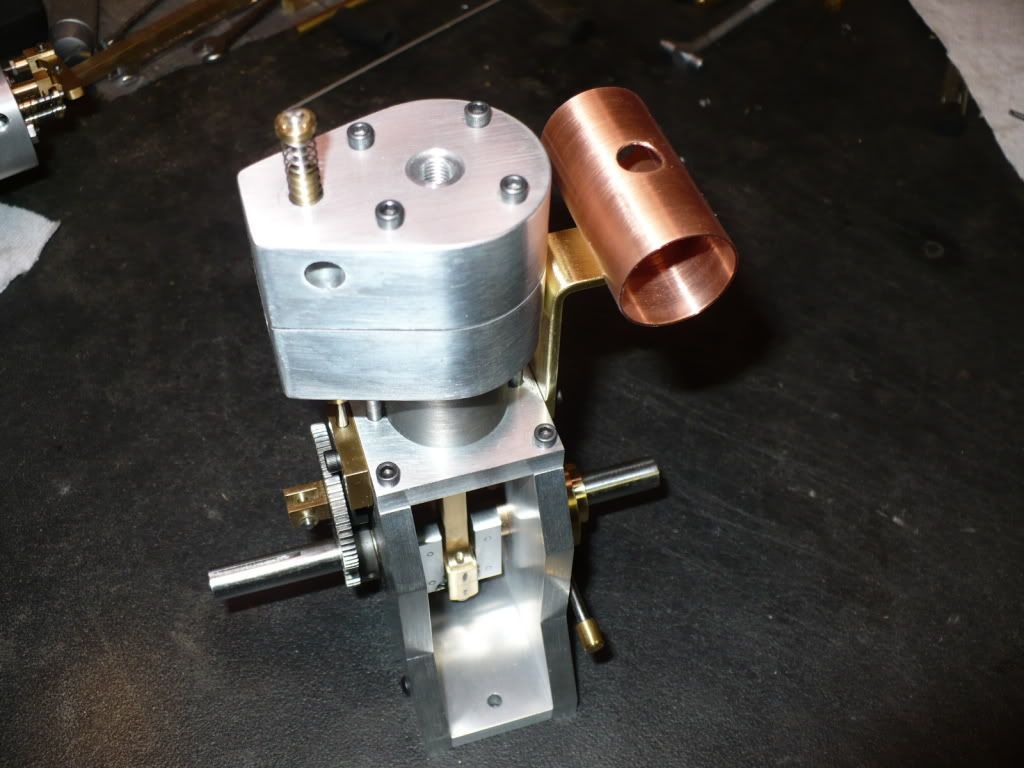
#299 I found out the tank can only be mounted on one side of the air cooled vertical version, and that the exhaust pipe won't clear it. I need to add another part to the list. A fitting is needed to re-direct the exhaust pipe.
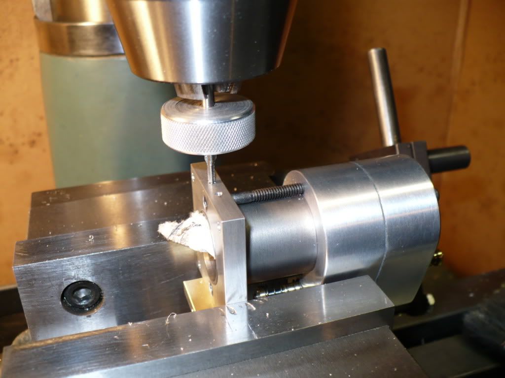
#300 "Oh my cheating ways!" I didn't want to take the head/cylinder assembly apart again, so I very carefully packed the bore with some paper towel and set it up in the mill to drill and tap for the 2-56 mounting screws. I took a bit of a risk and got away with it. I could have easily ended up with a major scratch or dent.
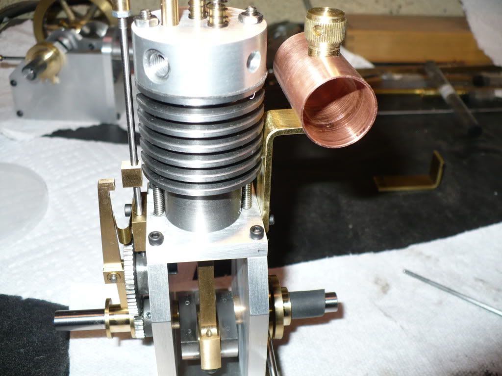
#301 Last picture. Here's how the tank will sit on the vertical 'F-Head' version. No clearance issue with the exhaust on this version.
Over the next few days I need make three metal sub bases for the horizontal versions, come up with a solution for re-directing the exhaust on the air cooled vertical, and come up with an assembly plan for the tanks and brackets. And I also need to make a choice on a finish system I'll use on the wood bases.
This project is far from over, and its turning out to be a little more complicated and time consuming than I originally thought. I always say "If it were easy it wouldn't be any fun!" ;D
-MB
Here I'm drilling the 4-40 clearance holes in the 1/8" thick mounting plates.
#294 To make the soldering easier I milled a line-up trough on the plates. The diameter of the tanks is 7/8", and the ball end mill I used is only 5/8". It should work to line up the assembly. I would have preferred to use the proper size end mill but I have to use what I have on hand and make it work.
#295 Below is a picture of a temporary assembly to see how the tanks will look. In addition to keeping the tanks low It will be necessary to make a base plate for all three horizontal versions to hike-up them up. Lately it seems that every time I make a part, it creates a need for another part.
#296 This is a picture of the clutter and confusion I have on my work bench.
#297 Cutting the wood for bases is not my 'cup of tea'. Usually it chips out when cut and routed, or it ends up with burn marks. I got lucky this time around. The two, two-piece bases in the upper left corner are for the vertical versions. On the horizontal versions the center-line of the crank is 2" up from the base, and on the vertical versions it only 1-1/4". This means that the addition of a 3/4" sub-base is required due to the 3-1/2" fly wheel diameter. Using a slab of aluminum would be odd to say the least so I used 3/4" wood (oak) for the base and sub-base instead.
The three bases for the horizontal versions are Mahogony, Walnut, and Canary wood in a clockwise rotation.
#298 On the Upshur web site the one vertical version shows the fuel tank mounted to a head bolt with a single strap. To avoid the need to remove the fuel tank if the head assembly needs to come off, I decided to make a separate bracket. Again, to keep in line with the spirit of the simple design I made the appropriate mounting bracket. It bolts to the cylinder base with two 2-56 screws, and I added the same milled line-up trough to simplify the assembly.
#299 I found out the tank can only be mounted on one side of the air cooled vertical version, and that the exhaust pipe won't clear it. I need to add another part to the list. A fitting is needed to re-direct the exhaust pipe.
#300 "Oh my cheating ways!" I didn't want to take the head/cylinder assembly apart again, so I very carefully packed the bore with some paper towel and set it up in the mill to drill and tap for the 2-56 mounting screws. I took a bit of a risk and got away with it. I could have easily ended up with a major scratch or dent.
#301 Last picture. Here's how the tank will sit on the vertical 'F-Head' version. No clearance issue with the exhaust on this version.
Over the next few days I need make three metal sub bases for the horizontal versions, come up with a solution for re-directing the exhaust on the air cooled vertical, and come up with an assembly plan for the tanks and brackets. And I also need to make a choice on a finish system I'll use on the wood bases.
This project is far from over, and its turning out to be a little more complicated and time consuming than I originally thought. I always say "If it were easy it wouldn't be any fun!" ;D
-MB
Rick---You are doing amazing work, and you have got to the point in your build where everybody has commented and now remain silent. I know, I reach that point in many of my builds where no one responds, and then I wonder if anybody is watching or if anybody cares. We all care very much, and we are all cheering you on. Keep the faith---your posts are really great, and we are all watching.----Brian
I second what Brian said. For me it reaches a point in builds of this caliber that you run out of words to say unless there is a specific question to ask. But rest assured we are still here, watching and soaking it up.
Ron
- Joined
- Dec 28, 2008
- Messages
- 1,731
- Reaction score
- 9
Hi Guys. Thanks for posting a concern on my behalf. It never crossed my mind that there might be a lack of interest in my project. I decided with my very first build thread shortly after joining HMEM, that If just one member is inspired, than any effort to post my progress and pictures would be worth while.
Last year my projects were short, and I built 10 very simple engines (one every 2 weeks) in a 5 month period.
This year my project is taking a long time, much longer than I anticipated. I never expected anyone to keep posting over and over on the same build thread. I'm aware that there is a good amount of members still interested in my project that have already said what they wanted to say. My only real concern is a disappointing out come to the project.
Hang in there every one, I have more than a month of shop time left, and the end of my project is getting near!
-MB
doc1955
Gone
- Joined
- Aug 26, 2009
- Messages
- 1,261
- Reaction score
- 164
And things are looking really GOOD!Metal Butcher said:Hang in there every one, I have more than a month of shop time left, and the end of my project is getting near!
-MB
It will be a treat when you get them running!
N_I_C_E W_O_R_K !!
Metal Butcher said:Hi Guys. Thanks for posting a concern on my behalf. It never crossed my mind that there might be a lack of interest in my project.
With almost 14,000 views I have to believe that there are a few people taking a look. Most wont post because the folks before have said what they would have said, but we are watching!!
- Joined
- Dec 28, 2008
- Messages
- 1,731
- Reaction score
- 9
Thanks everyone for all your support and the uplifting comments!
I just came up from a very productive but tiring day down in the shop, In plain English, I'm whipped!
I made the three aluminum bases that I felt would add to the overall look and stability of the horizontal models. They bolt to the original frame plates from underneath, and they will sit directly on the wood. Four corner bolts will be used to secure the added base plates to the wood bases. I think Hamilton tried to keep the engines as simple as possible by omitting this little unnecessary detain. I like the looks of the addition, and feel that it was a worth the extra effort. The most time consuming part of making the aluminum bases was of course the file work. It takes a lot of time to get all the surfaces smooth and flat, with slightly champhered, but crisp corners.
I got "Honey's" expert opinion, and she said that without the added aluminum bases, the engines looked like they were missing something, and I have to agree.
I also managed to drill the holes and counter bore the wood bases from underneath for washers and nuts. The bases were to large for my milling vise and needed to be hand held for the drilling and milling operations. A bit of a nerve racking way to go, but it turned out well.
I'll include the bases in my next picture post early next week.
-MB
Metal Butcher said:I changed my plan and decided to try making a washer from Delrin (Acetal) to see if it might work.
Good idea, can see why the spring washer gave fits, didn't like the slot at all.
Robert
- Joined
- Dec 28, 2008
- Messages
- 1,731
- Reaction score
- 9
Foozer said:Good idea, can see why the spring washer gave fits, didn't like the slot at all.
Robert
That's correct Robert. The use of a spring washer in a stepped groove is destined to fail. Since the washers have a curvature, any rotational shift will drop the high sides of the spring washer down into the step. Once that happens it becomes loose and starts to scrape on the corner of the step. The thicker Delrin washer is flat, and it does not display any tendency to rotate, providing an adjustable grip with smooth movement.
-MB
- Joined
- Dec 28, 2008
- Messages
- 1,731
- Reaction score
- 9
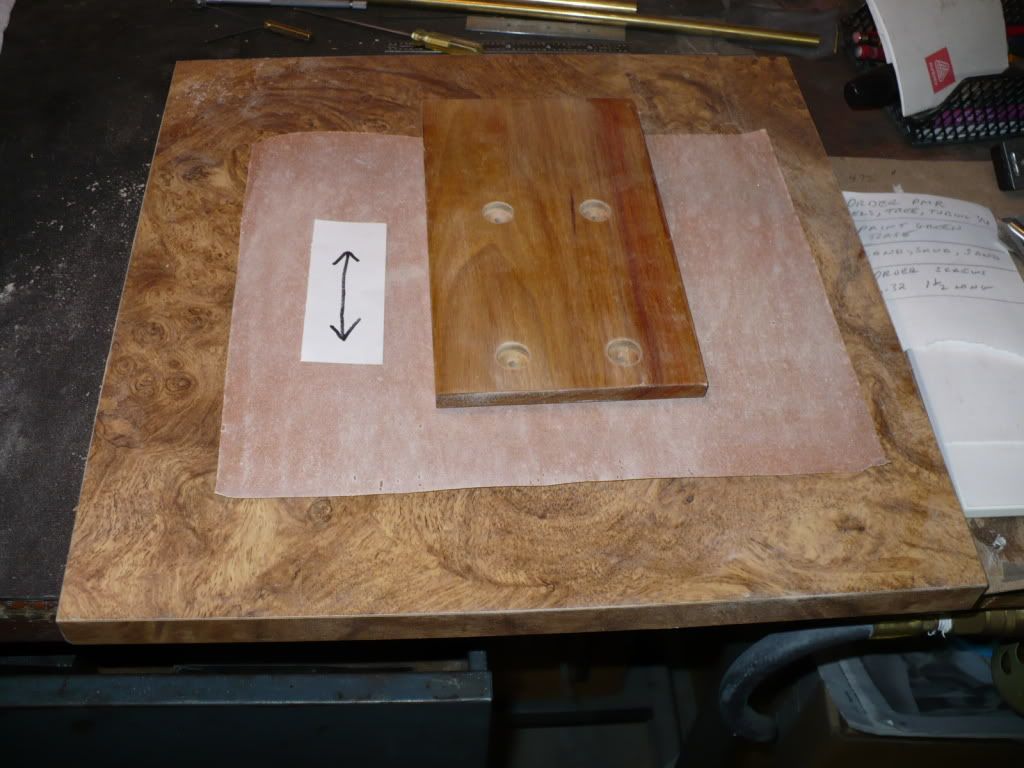
#302 Over the last few days I have been applying coats of a wax free shellac sanding sealer to the wood bases. Each coat was sanded off before another was applied. The purpose of all the coats is to fill in and seal the grain. The finish will be three coats of Varathane Profesional semi-gloss. A few years back I found out a that wood must be sanded with the grain. In the picture below I show the 'block sanding' style I use with a Formica covered board to level the woods surface. The sides are done the same way. For the routed part of the edges I use a short piece of scrap metal wrapped with sand paper.
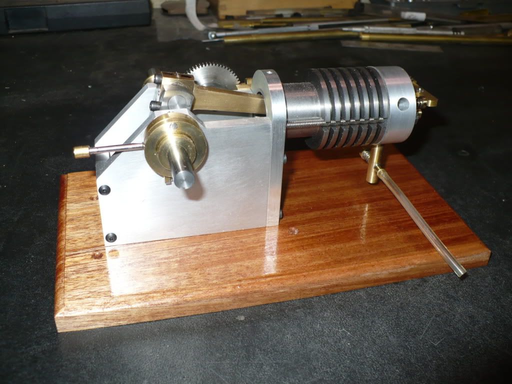
#303 In this picture you can see how the frame of the engine looks sitting directly on a wood base. Mounting the engine this way would leave the center-line of the carburetor needle to low for the fuel level at the top of the gas tank.
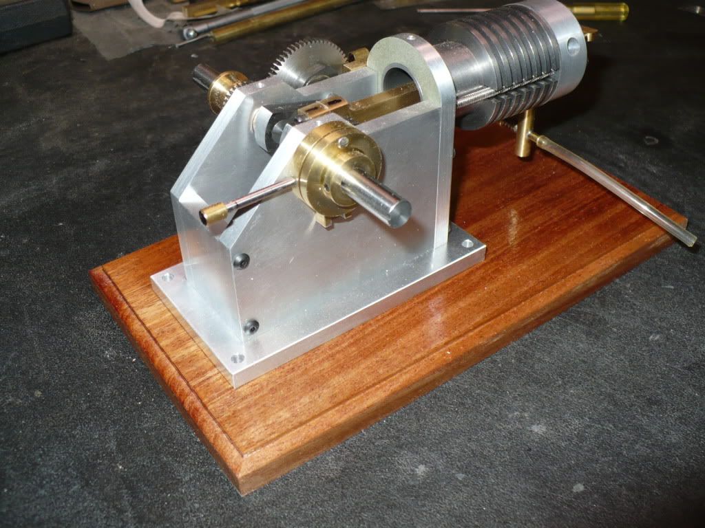
#304 In this picture I added an aluminum base to raise the carburetor up, and at the same time add a minor cosmetic detail to the engine's frame. The engine base was a detail that I felt was missing.
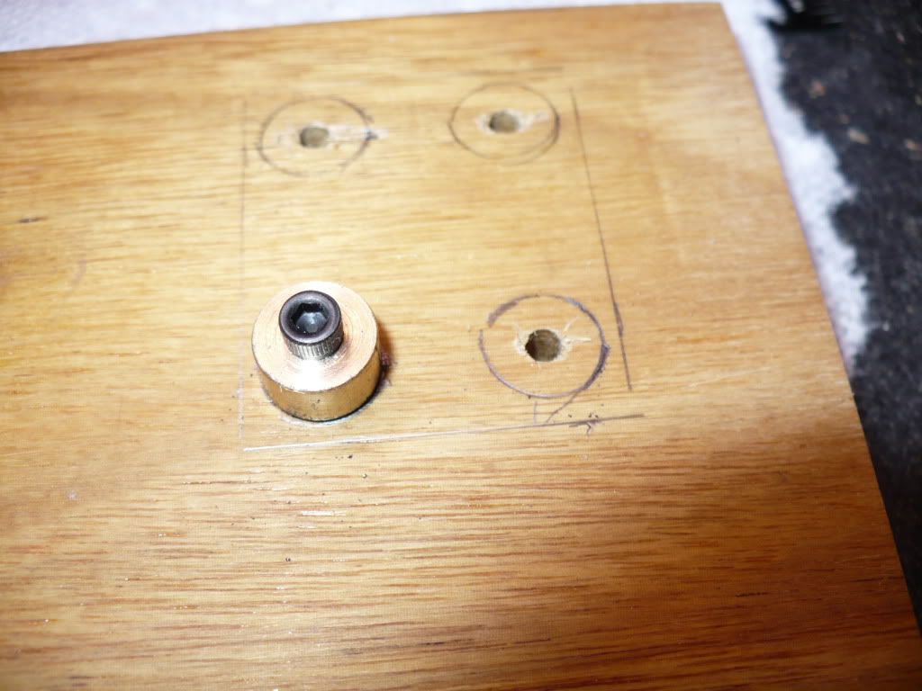
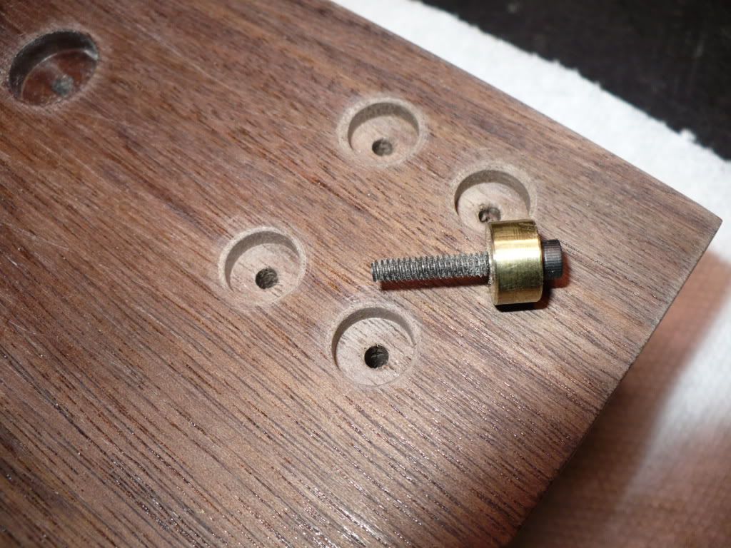
#305 I used an end mill to create a counter sink under the wood bases. This will conceal the nuts and washers that will go on the bolts, that will secure the engines and gas tanks on top of the wood bases.
My milling vise is too small to hold the bases so I had to eye ball the locations for the end milled areas. To make this easier I made a brass button to pencil mark the locations making the end mill line up a bit easier.
#306 Here's a base already milled out for the gas tank mounting bolts. I went .150" deep with a 3/8" end mill to allow plenty of clearance for a 4-40 nut and washer. The engine mounting holes and countersinks were done previously. For those I used a 1/2" end mill and went .200" deep for 6-32 nuts and washers.
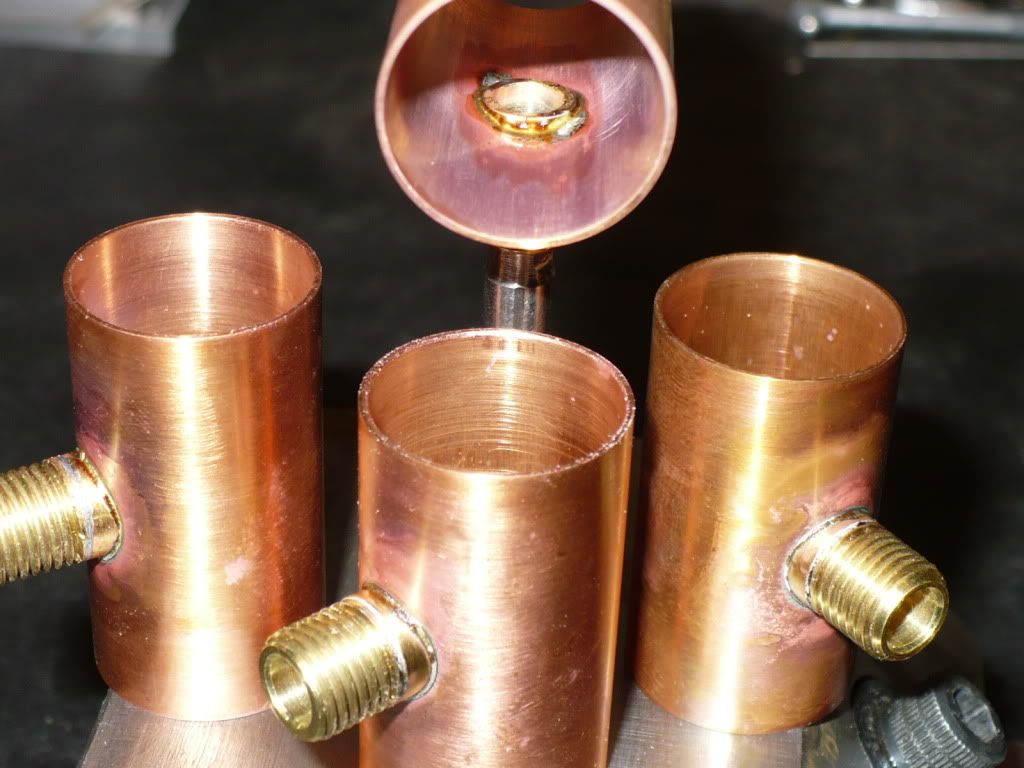
#307 I started the assembly of the fuel tanks by soldering the gas cap nipples on first. I used small pieces of 60/40 soft solder placed on the inside of the tank, and applied the heat to the nipple from the out side. The solder is attracted to the heat and pulls through the joint using this method.
If you use this method with the intention of adding the end caps latter, its best to use a high temperature soft solder or a high temperature silver solder, for the first soldered on part to avoid melting the solder used on the nipple when you add the end caps. I didn't remember this, and one of the threaded nipples let loose and had to be re-soldered as a last step. The repair made a mess and created a wider spread of the visible solder joint. This can be seen in a picture further along in this post.
In the back ground one assembly is cooling down. I set the nipple over a stepped rod held in a vise to hold it up while I soldered it together.
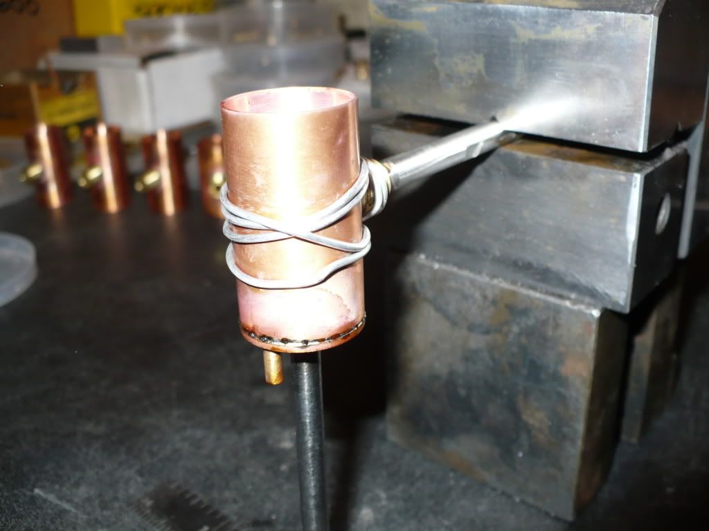
#308 Using the same set up shown in the previous picture, I stood the vise on end to solder on the end cap with the fuel line nipple pressed in place. I used a snug fitting rod from underneath, to hold the end cap up and in place. After all the contact surfaces were fluxed I set small pillows of solder around the inside perimeter of the end cap and applied heat from the out side and all around till a hint of solder came through the joint.
I wrapped the assembly with aluminum wire before soldering as a safety precaution. The last thing you want is a hot piece of pipe landing in your lap!
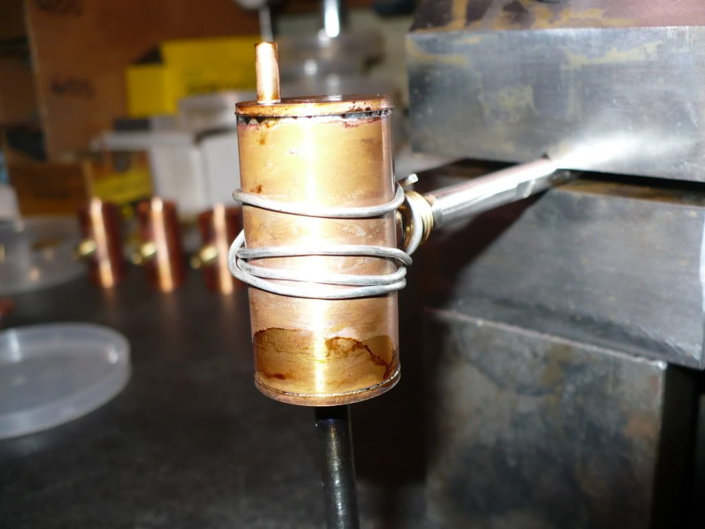
#309 After good cooling the assembly was preped with sanding and flux, and installed with a 160 degrees rotation on the fixture rod. An end cap was prepped with flux and solder pillows, and then installed from underneath supported with a steel rod.

#310 Again the heat was applied just till the first hint of solder could be seen. With the soldering finished the tank is ready for the final clean up and finishing steps.
#311 The soldering of the five tanks is finished. It took the better part of the day with most of my time spent waiting for the cool downs.
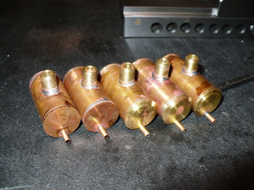
#312 Here's how a tank looks after a little sand papering. I would love to copper plate these to hide the solder joints. Maybe by next time around, when I find the time to research this idea.
#313 The filler neck nipple shifted (melted) and had to be re-soldered on one on the left.
-MB
#303 In this picture you can see how the frame of the engine looks sitting directly on a wood base. Mounting the engine this way would leave the center-line of the carburetor needle to low for the fuel level at the top of the gas tank.
#304 In this picture I added an aluminum base to raise the carburetor up, and at the same time add a minor cosmetic detail to the engine's frame. The engine base was a detail that I felt was missing.
#305 I used an end mill to create a counter sink under the wood bases. This will conceal the nuts and washers that will go on the bolts, that will secure the engines and gas tanks on top of the wood bases.
My milling vise is too small to hold the bases so I had to eye ball the locations for the end milled areas. To make this easier I made a brass button to pencil mark the locations making the end mill line up a bit easier.
#306 Here's a base already milled out for the gas tank mounting bolts. I went .150" deep with a 3/8" end mill to allow plenty of clearance for a 4-40 nut and washer. The engine mounting holes and countersinks were done previously. For those I used a 1/2" end mill and went .200" deep for 6-32 nuts and washers.
#307 I started the assembly of the fuel tanks by soldering the gas cap nipples on first. I used small pieces of 60/40 soft solder placed on the inside of the tank, and applied the heat to the nipple from the out side. The solder is attracted to the heat and pulls through the joint using this method.
If you use this method with the intention of adding the end caps latter, its best to use a high temperature soft solder or a high temperature silver solder, for the first soldered on part to avoid melting the solder used on the nipple when you add the end caps. I didn't remember this, and one of the threaded nipples let loose and had to be re-soldered as a last step. The repair made a mess and created a wider spread of the visible solder joint. This can be seen in a picture further along in this post.
In the back ground one assembly is cooling down. I set the nipple over a stepped rod held in a vise to hold it up while I soldered it together.
#308 Using the same set up shown in the previous picture, I stood the vise on end to solder on the end cap with the fuel line nipple pressed in place. I used a snug fitting rod from underneath, to hold the end cap up and in place. After all the contact surfaces were fluxed I set small pillows of solder around the inside perimeter of the end cap and applied heat from the out side and all around till a hint of solder came through the joint.
I wrapped the assembly with aluminum wire before soldering as a safety precaution. The last thing you want is a hot piece of pipe landing in your lap!
#309 After good cooling the assembly was preped with sanding and flux, and installed with a 160 degrees rotation on the fixture rod. An end cap was prepped with flux and solder pillows, and then installed from underneath supported with a steel rod.
#310 Again the heat was applied just till the first hint of solder could be seen. With the soldering finished the tank is ready for the final clean up and finishing steps.
#311 The soldering of the five tanks is finished. It took the better part of the day with most of my time spent waiting for the cool downs.
#312 Here's how a tank looks after a little sand papering. I would love to copper plate these to hide the solder joints. Maybe by next time around, when I find the time to research this idea.
#313 The filler neck nipple shifted (melted) and had to be re-soldered on one on the left.
-MB
- Joined
- Aug 8, 2009
- Messages
- 930
- Reaction score
- 12
Metal Butcher said:It took the better part of the day with most of my time spent waiting for the cool downs.
-MB
I have this problem too, but its got nothing to do with machining.
Nice looking tanks, Hombre....
-Trout
Similar threads
- Replies
- 356
- Views
- 55K