
You are using an out of date browser. It may not display this or other websites correctly.
You should upgrade or use an alternative browser.
You should upgrade or use an alternative browser.
MB building Upshur Farm Engines.
- Thread starter Metal Butcher
- Start date


Help Support Home Model Engine Machinist Forum:
This site may earn a commission from merchant affiliate
links, including eBay, Amazon, and others.

Rick---Those adjustable blocks are a great idea. I had actually designed something similar on my Kerzel, because its a real bear to get everything positioned just right for the hit and miss effect. Unfortunately, on the kerzel there is simply no EASY way of making one adjustable. I ended up filing a bit off the step in the lever, then realizing I'd filed off too much and had to silver solder the step back up again. I went through that bit of foolishness about 4 times before I found its "sweet spot".----Brian
- Joined
- Dec 28, 2008
- Messages
- 1,731
- Reaction score
- 9
jim hay said:Hi MB
I will try to upload the pics we talked about , concerning the governor latch out. have a good one Jim
Jim your engine looks great! :bow:
Thanks for posting the great close-up picture. As you know the plans don't show a way to build the F-Head as a hit-miss engine. Your picture shows how you overcame the normal rotation of push rod. The rotation would make it impossible to use a solder on, or set screwed stop block.
-MB
- Joined
- Dec 28, 2008
- Messages
- 1,731
- Reaction score
- 9
Brian Rupnow said:Rick---Those adjustable blocks are a great idea. I had actually designed something similar on my Kerzel, because its a real bear to get everything positioned just right for the hit and miss effect. Unfortunately, on the kerzel there is simply no EASY way of making one adjustable. I ended up filing a bit off the step in the lever, then realizing I'd filed off too much and had to silver solder the step back up again. I went through that bit of foolishness about 4 times before I found its "sweet spot".----Brian
Thanks Brian. The adjustable stop blocks I designed will only work on the versions that use a non rotating push rod. They are kept from from rotating by using a locking clevis at the rocker arm pivot point.
On the F-Head versions the clevis,and the lock out arm shown in the plan set won't fit.
It will take a little redesigning to adapt the governor parts needed to make the F-Head verstions work as hit-n-miss engines.
The project seems to get more and more complicated as it progresses.
-MB
- Joined
- Dec 28, 2008
- Messages
- 1,731
- Reaction score
- 9
ozzie46 said:Great work MB.
I started 5 engines once. 3 got finished. Still need minor work on all of them so I guess really NOT finished. ::
Ron
Hi Ron. If they are a Upshur's, then its interesting to hear that you are also building 5 engines. What in the world is it that possessed us to build more than one engine at a time? Was it the picture of multiple builds on Hamiltons web site? Was it the plan set that offered too many variations? Was it a subconscious desire to put on an impressive show? Was it a decision driven by an insatiable need to impress our selves? :shrug:
Or are we just plain crazy! I'm leaning towards crazy, as far as I'm concerned! scratch.gif Rof} Rof}
-MB
- Joined
- Dec 28, 2008
- Messages
- 1,731
- Reaction score
- 9
#262 Hi guys. Yesterday I made all of the head gaskets using 1/16" Felpro rubber fiber material. The were cut out using gasket punches and an Exacto knife. The two mounting holes on each head were punched through using a drilled piece of scrap aluminum for support, and then the drill was reversed in the chuck and used punch press style. Its not the best way to treat a drill bit but it is a quick method that punches a clean hole. I save my dull clearance size drill bits for this purpose.
Today I worked on completing the installation of the valves and guides. To prevent damage to the small valve guides I made a simple fixture that would apply pressure on the shoulder of the guide rather than on its vulnerable drilled and reamed end. In addition to the press fit I coated the parts with #609 Loctite out of habit. If I were relying on the Loctite to hold them in, the use of #620 high temperature Loctite would be a better choice.
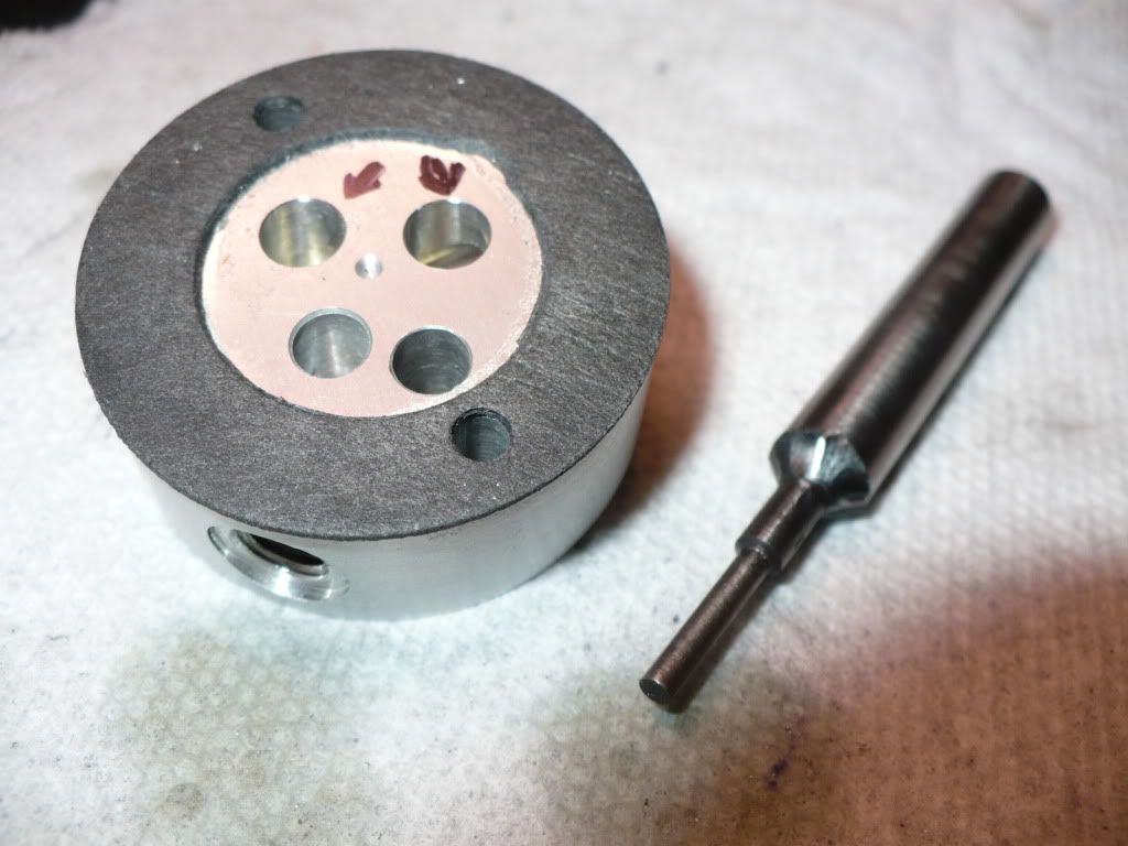
#263 With the valve guides in place they become a precision guide for a valve seat cutter. This is the best method to cut a seat that is concentric and perpendicular with the bore, since its the very same bore that will guide the valve stem. What system could be more perfect. Now that I've tried this method I can say this is a very simple, easy, and fool proof way to go. All it took was about six light twists to cut a perfect seat. The valve stems fit so well that lapping seemed pointless. However, I did lap them with some Flitz metal polish, and a few light twists just to be sure. I cut the seats about .015" wide, and that's all I need. The arrows point to the finished valve seats.
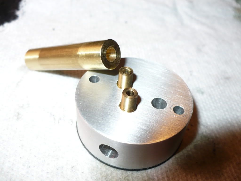
#264 Below is a view of one of the 5 heads with the valve stems in place. I made the valve stems using brass for the heads and found out that the higher temperature of the exhaust valves might cause thermal shock loading to the brass. So To be on the safe side I made up new exhaust valve assemblies with steel heads. Since the intake valves will run at a lower temperature the brass heads should be fine.
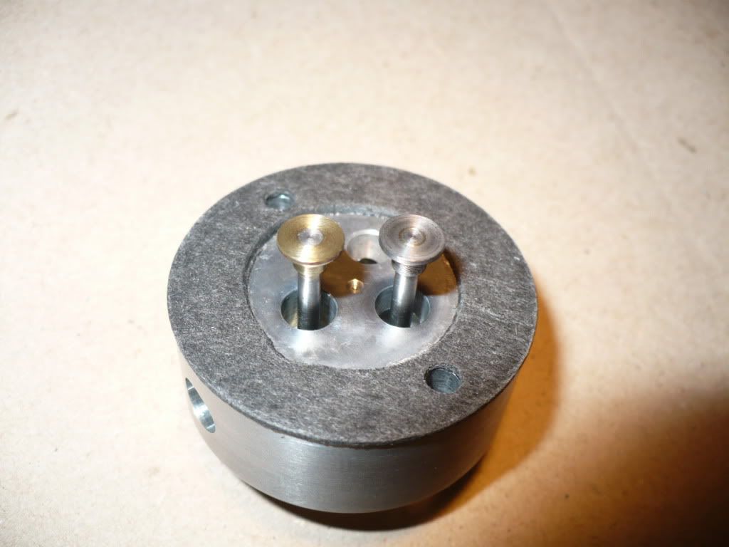
#265 I took my time, and spent a very pleasant day assembling all of the the valves. It doesn't get better than this. I spent a great deal of time analyzing and worrying about this very critical area of I.C. engine building. The first time is always the hardest when dealing with the unknown.
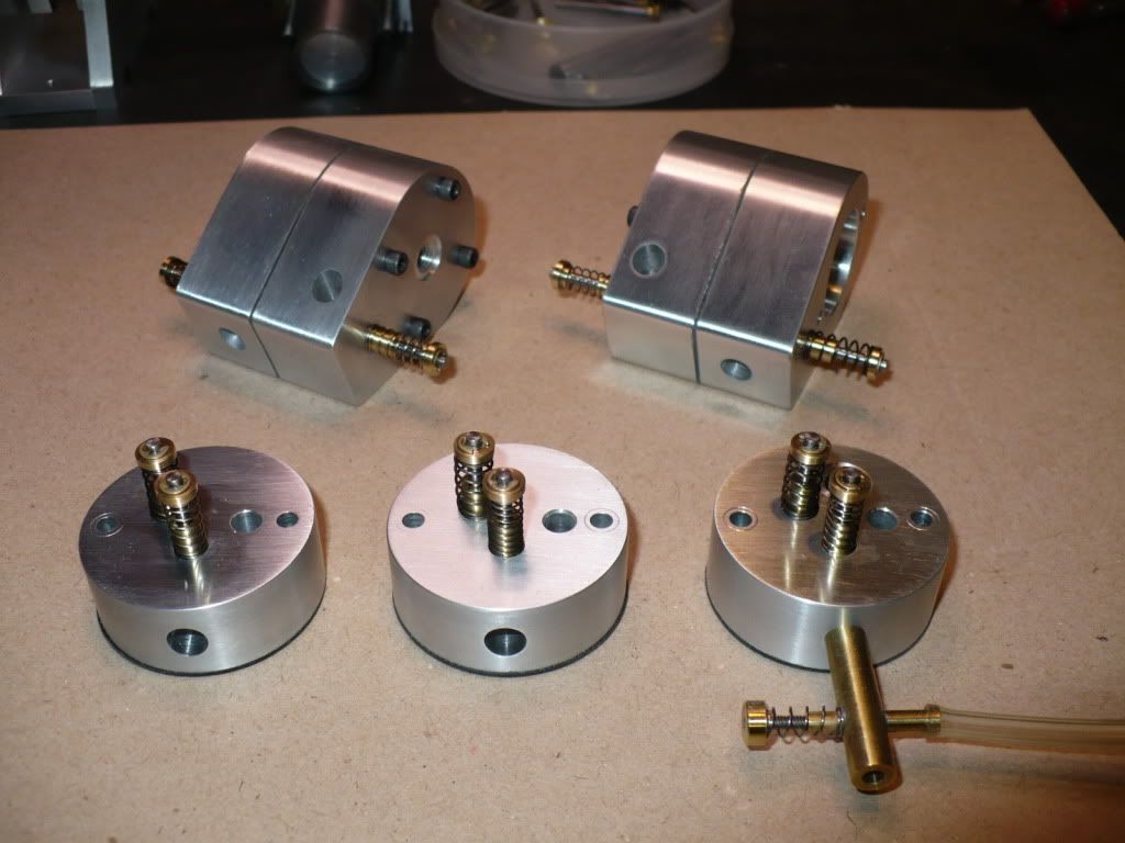
#266 This is not even half of the parts for this project. I have more in a bench drawer and six boxes of parts and components scattered about the shop. Finding a particular part can be quite a challenge!
-MB
Today I worked on completing the installation of the valves and guides. To prevent damage to the small valve guides I made a simple fixture that would apply pressure on the shoulder of the guide rather than on its vulnerable drilled and reamed end. In addition to the press fit I coated the parts with #609 Loctite out of habit. If I were relying on the Loctite to hold them in, the use of #620 high temperature Loctite would be a better choice.
#263 With the valve guides in place they become a precision guide for a valve seat cutter. This is the best method to cut a seat that is concentric and perpendicular with the bore, since its the very same bore that will guide the valve stem. What system could be more perfect. Now that I've tried this method I can say this is a very simple, easy, and fool proof way to go. All it took was about six light twists to cut a perfect seat. The valve stems fit so well that lapping seemed pointless. However, I did lap them with some Flitz metal polish, and a few light twists just to be sure. I cut the seats about .015" wide, and that's all I need. The arrows point to the finished valve seats.
#264 Below is a view of one of the 5 heads with the valve stems in place. I made the valve stems using brass for the heads and found out that the higher temperature of the exhaust valves might cause thermal shock loading to the brass. So To be on the safe side I made up new exhaust valve assemblies with steel heads. Since the intake valves will run at a lower temperature the brass heads should be fine.
#265 I took my time, and spent a very pleasant day assembling all of the the valves. It doesn't get better than this. I spent a great deal of time analyzing and worrying about this very critical area of I.C. engine building. The first time is always the hardest when dealing with the unknown.
#266 This is not even half of the parts for this project. I have more in a bench drawer and six boxes of parts and components scattered about the shop. Finding a particular part can be quite a challenge!
-MB
MB,
I haven't worked with miniature IC engines before. Being a decades old diesel mechanic, the engines I'm familiar with weigh in a little heavier than these works of art. But if these little ones are anything like the big ones...
Can I suggest wider valve seats? You want a thick edge on the valve, a wide enough seat for good contact, and long enough dwell closed for the heat to transfer into the head, or the exhaust valves will burn. :'(
You're work is too beautiful to see that happen. Your work and your presentation are over the top. :bow:
Please get the heat out of those valves. I can't wait to hear these puppies spin up some RPM.
Cherokee---These engines are intended to be a very low revving engine running at a more or less constant speed. Conventional wisdom is that the narrower the valve seats are, the better. Since during the "Miss cycle" the exhaust valve remains open and fresh air is pulled in thru the intake and expelled out over the exhaust valve without any ignition occuring, these valves run very cool so don't depend on heat transfer thru the seat area to cool the valves.
Well, how about that? I like to learn something new every day. Thanks Brian. Tell the truth, I wasn't feeling too warm and fuzzy about the brass intake valve either, but if your running enough fresh air over the valves, the heat may not be a problem. Thm:
- Joined
- Dec 28, 2008
- Messages
- 1,731
- Reaction score
- 9
CherokeeJ, Thanks for taking an interest in my project, and for sharing you knowledge on how valves are cooled by heat transfer.
Brian, thanks for your reply (I was out doing some grocery shopping), I couldn't have explained it any better.
Mmmmm, chocolate pie, my favorite!
-MB
Brian, thanks for your reply (I was out doing some grocery shopping), I couldn't have explained it any better.
Mmmmm, chocolate pie, my favorite!
-MB
- Joined
- Dec 28, 2008
- Messages
- 1,731
- Reaction score
- 9
#267 I spent the last few days cleaning up overlooked marks and test fitting parts. I became disenchanted with all of the squeaky tight clearance holes that were drilled #35 and opened each one up with a #33 drill. Then I re-assembled all the parts and took everything apart again just to be sure I was happy.
Two things became apparent. The first is that I will be taking them apart again to drill a threaded hole for attaching an adjustable mount for the hall sensors which is still in the planing stage. And the second is that I need to plan a little more carefully in the future to ovoid wasting two or three days getting nowhere!
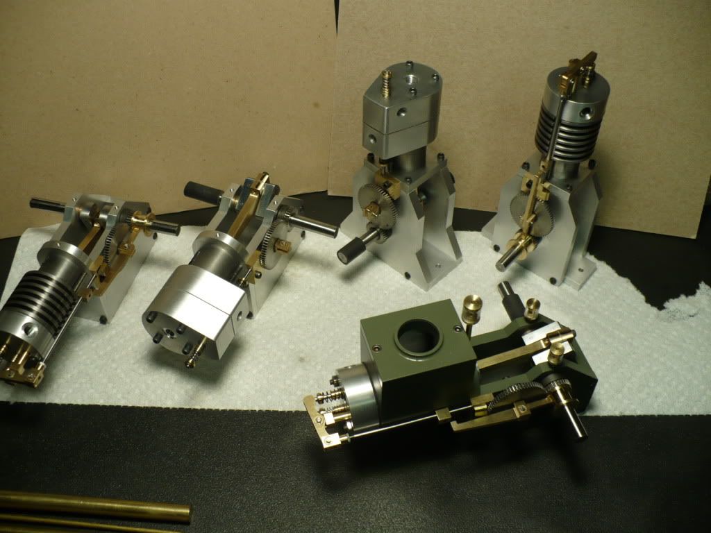
Below is a group shot of the five variations I'm building.
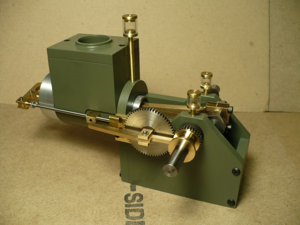
#268 Below is my modified version of the water cooled horizontal. I painted it my traditional color that I call 'Trout Green'.
I'm hoping this close-up will inspire one of our members who is working on his own version, in a secret shop some where on the west coast!
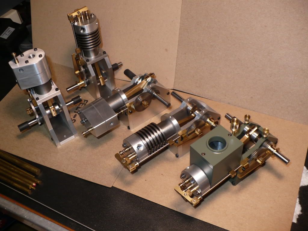
#269 Getting closer and closer. But there is still a few parts and problems, to finish and solve. I remember way back when I looked over the plan set and thought "This is gonna be a piece of cake!" Live and learn. :big:
-MB
Two things became apparent. The first is that I will be taking them apart again to drill a threaded hole for attaching an adjustable mount for the hall sensors which is still in the planing stage. And the second is that I need to plan a little more carefully in the future to ovoid wasting two or three days getting nowhere!
Below is a group shot of the five variations I'm building.
#268 Below is my modified version of the water cooled horizontal. I painted it my traditional color that I call 'Trout Green'.
I'm hoping this close-up will inspire one of our members who is working on his own version, in a secret shop some where on the west coast!
#269 Getting closer and closer. But there is still a few parts and problems, to finish and solve. I remember way back when I looked over the plan set and thought "This is gonna be a piece of cake!" Live and learn. :big:
-MB
zeeprogrammer
Well-Known Member
- Joined
- Mar 14, 2009
- Messages
- 3,362
- Reaction score
- 13
That's a beautiful set of engines. Awesome.
- Joined
- Dec 28, 2008
- Messages
- 1,731
- Reaction score
- 9
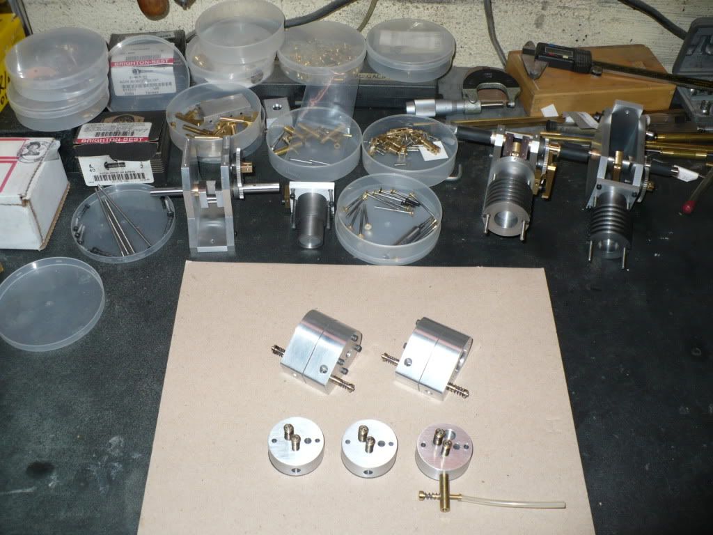
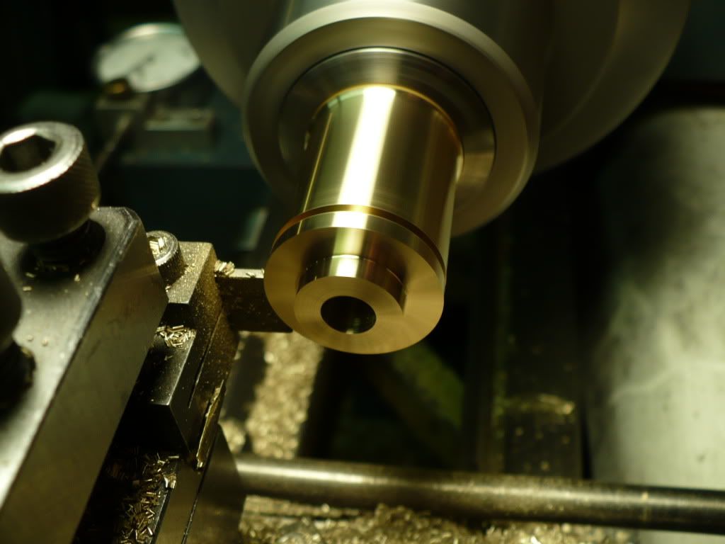
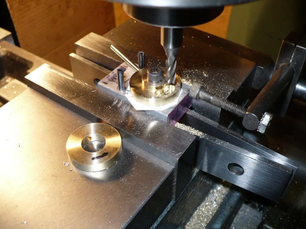
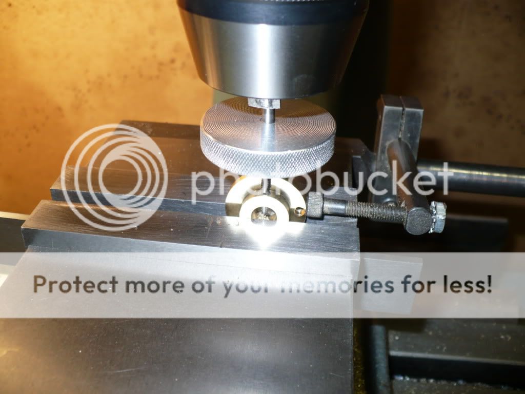
#270 For today's post I made the adjustable 1" carrier disc for the hall sensor, and the 1" carrier disc for the magnet that will rotate with the crank and trip the sensor. In the picture I'm cutting off one of the rotating discs that will carry a magnet.
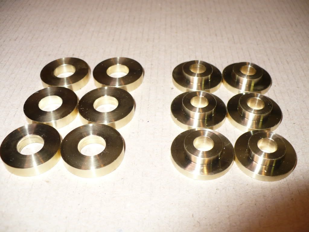
#271 On the left are the blanks that will become the discs for the hall sensors, and on the right are the blanks that will become the carrier discs for the magnets.
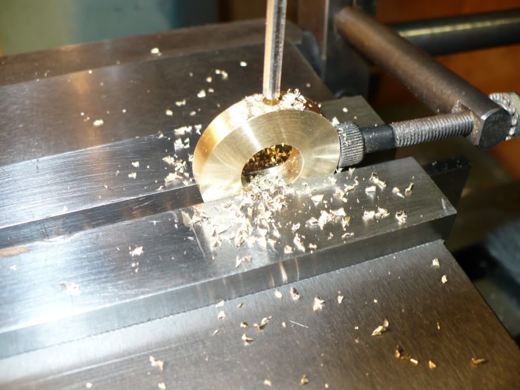
#272 The first step on the sensor disc was to drill and ream a hole for a rod that will be used for fine adjustments. A temporary rod will be inserted and used to fixture the discs in the next machining steps.
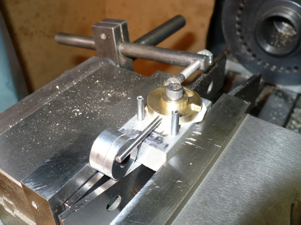
#273 I made a simple fixture to locate and rotate the sensor disc to mill out a slot for a captive screw that will allow movement of the disc for adjustments while the engine is running.
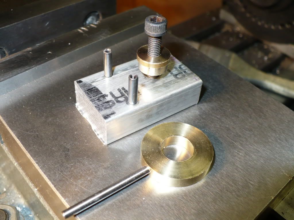
#274 The temporary rod is used to rotate the disc back and forth while the end mill is lowered slowly to a depth of the thickness of a cap screw head plus .020" for a .010 spring steel washer. The second step (not shown) was to use a smaller end mill and go all the way through for the threaded part of the cap screw.
#275 I used the same fixture with the aid of space blocks to center a shallow milled slot for the hall sensor. I milled it the thickness of the sensor plus .004" so that when its glued in place it will be just below the surface and out of harms way.
#276 I got lucky and a 5/32" end mill made a perfect width slot for the sensor. The sensors I'm using are HAL506UA-A from Symmetry Electronics, Corp.
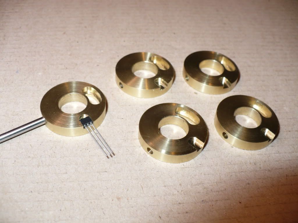
#277 I made another simple fixture by drilling and tapping a hole for a cap screw that fit the bore of the carrier disc for the magnet. This made it easier to drill and ream all of the .125" holes for the .1245" cylindrical magnets.
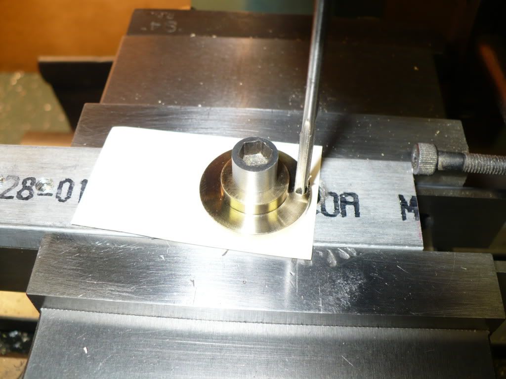
#278 I tapped the hub on the magnet carrier disc for a 4-40 set screw. The location was not important so I offset it by 90* from the magnet to avoid fighting with the hex wrench during the initial adjustment since these are very powerfull little magnets.
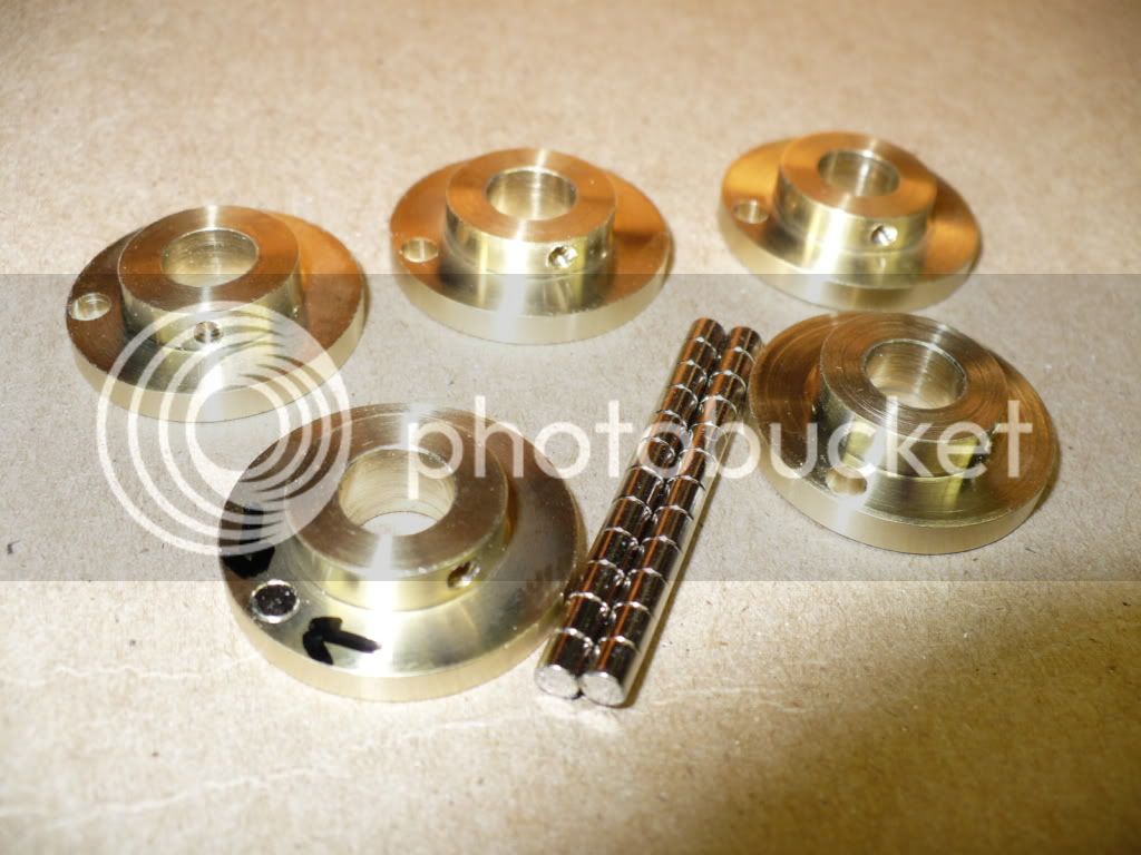
#279 The magnets I'm using on this project are cylindrical 1/8" x 1/8" D22-N52 from K&J Magnetics.
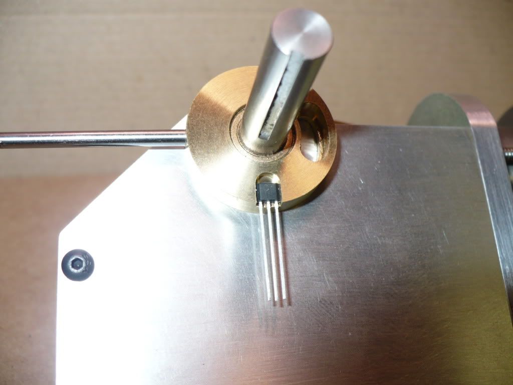
#280 This is the position the hall sensor will be mounted in. All of the engine side frames will have to come off to drill and tap for the mounting/adjusting screws.
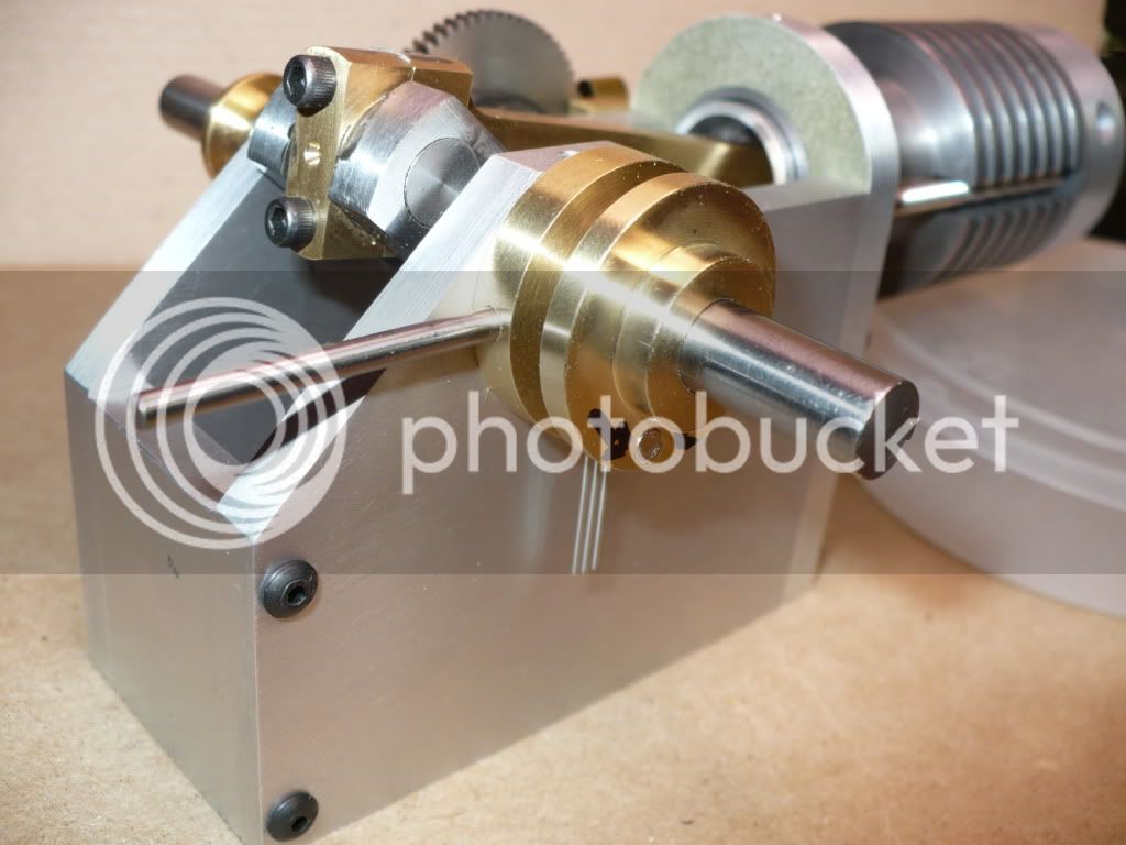
#281 The magnet carrier is being installed to give a better idea of how the system will go together and look.
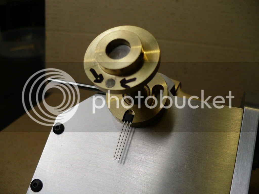
#282 Here's another view of my set up. The gap between the discs will be set at about .030". I might just machine up some .030" spacers to eliminate the spacing issue during the initial set up.
-MB
#271 On the left are the blanks that will become the discs for the hall sensors, and on the right are the blanks that will become the carrier discs for the magnets.
#272 The first step on the sensor disc was to drill and ream a hole for a rod that will be used for fine adjustments. A temporary rod will be inserted and used to fixture the discs in the next machining steps.
#273 I made a simple fixture to locate and rotate the sensor disc to mill out a slot for a captive screw that will allow movement of the disc for adjustments while the engine is running.
#274 The temporary rod is used to rotate the disc back and forth while the end mill is lowered slowly to a depth of the thickness of a cap screw head plus .020" for a .010 spring steel washer. The second step (not shown) was to use a smaller end mill and go all the way through for the threaded part of the cap screw.
#275 I used the same fixture with the aid of space blocks to center a shallow milled slot for the hall sensor. I milled it the thickness of the sensor plus .004" so that when its glued in place it will be just below the surface and out of harms way.
#276 I got lucky and a 5/32" end mill made a perfect width slot for the sensor. The sensors I'm using are HAL506UA-A from Symmetry Electronics, Corp.
#277 I made another simple fixture by drilling and tapping a hole for a cap screw that fit the bore of the carrier disc for the magnet. This made it easier to drill and ream all of the .125" holes for the .1245" cylindrical magnets.
#278 I tapped the hub on the magnet carrier disc for a 4-40 set screw. The location was not important so I offset it by 90* from the magnet to avoid fighting with the hex wrench during the initial adjustment since these are very powerfull little magnets.
#279 The magnets I'm using on this project are cylindrical 1/8" x 1/8" D22-N52 from K&J Magnetics.
#280 This is the position the hall sensor will be mounted in. All of the engine side frames will have to come off to drill and tap for the mounting/adjusting screws.
#281 The magnet carrier is being installed to give a better idea of how the system will go together and look.
#282 Here's another view of my set up. The gap between the discs will be set at about .030". I might just machine up some .030" spacers to eliminate the spacing issue during the initial set up.
-MB
doc1955
Gone
- Joined
- Aug 26, 2009
- Messages
- 1,261
- Reaction score
- 163
I just now am catching up on this thread and I am at a loss words just! Simply beautiful! To do a multi build of different engines I'm just amazed. I don't know how I've been missing this thread. I did fire off an e-mail to try and get a set of drawings Thanks for the info. Keep up the good work you are doing some dazzling work! :bow: :bow: :bow: :bow:
MB, your work is inspirational, just amazing..... :bow:
Strange that in the last few days I have been thinking about mounting the hall effect device and it's magnet and came up with the few ideas, but what you have just done is perfect and I am sure my Upsher will have something very similar... ;D
Dave
Strange that in the last few days I have been thinking about mounting the hall effect device and it's magnet and came up with the few ideas, but what you have just done is perfect and I am sure my Upsher will have something very similar... ;D
Dave
Similar threads
- Replies
- 356
- Views
- 54K