MB building Upshur Farm Engines.

Home Model Engine Machinist Forum

Help Support Home Model Engine Machinist Forum:

This site may earn a commission from merchant affiliate links, including eBay, Amazon, and others.
doc1955 said:
I just now am catching up on this thread and I am at a loss words just! Simply beautiful! To do a multi build of different engines I'm just amazed. I don't know how I've been missing this thread. I did fire off an e-mail to try and get a set of drawings Thanks for the info. Keep up the good work you are doing some dazzling work! :bow: :bow: :bow: :bow:

Thanks or the compliment doc! With out an audience its just practice. Knowing that my project is being followed and watched motivates me to give my best performance.

-MB
 
DaveRC said:
MB, your work is inspirational, just amazing..... :bow:

Strange that in the last few days I have been thinking about mounting the hall effect device and it's magnet and came up with the few ideas, but what you have just done is perfect and I am sure my Upsher will have something very similar... ;D

Dave

Hi Dave. Thanks for the compliment. I tossed ideas around for quite a while before coming up with this simple solution. I used a 3/16" disc for the sensor mount to have enough thickness to countersink the mounting screw. A 4-40 barley fits between the bore and the outer diameter, so you might consider using a smaller 2-56 screw or using a larger disc like 1-1/8 or 1-1/4.

The magnet disc is 1/8" thick at the major diameter to accommodate the magnet, and the hub width is .150" to allow plenty of room for a 4-40 set screw.

The Neodymium -52 grade magnets are slightly attracted to the brass, I don't know if this matters, but you might want to look into it, or consider using aluminum instead if this is any thing to be concerned about.

-MB
 
Hi MB,

Thanks for the info... I did ponder for a while about what material to use, I have reservations about using aluminium as this is has some weird magnetic properties when spinning and was not sure how that would affect the sensor. I have some white Delrin I may use, If made carefully (meaning neat) I don't think this should look out of place.

Dave
 
Metal Butcher said:
Thanks or the compliment doc! With out an audience its just practice. Knowing that my project is being followed and watched motivates me to give my best performance.

-MB
Boy do I know that feeling!

Now that I have found this thread I will now be watching. My next build I think I'm going to do away with the points and go with a set like you are doing.
You are doing some mighty fine work! :bow:
 
Really enjoying following along, MB. Beautiful and interesting work, as usual. What kind of ignition system will you be using with the Hall switches, and will you be locking out every other spark somehow, or firing each revolution? Sorry if you've already addressed that and I overlooked it.

Regards,
Rudy

 
rudydubya said:
Really enjoying following along, MB. Beautiful and interesting work, as usual. What kind of ignition system will you be using with the Hall switches, and will you be locking out every other spark somehow, or firing each revolution? Sorry if you've already addressed that and I overlooked it.

Regards,
Rudy

Hi Rudy. I haven't covered any details about the ignition system on my thread yet. I ordered a CDI system from S/S Machine and Engineering. And I don't know if the waste spark can be locked-out on mine or not. Or if I need to.

I ordered the 'Basic single spark CDI ignition system' for $55. For a single build the 'Complete' system for $105 may be your best bet. I opted to buy separate components from different sources like the magnets, hall sensors, etc, since I need to wire up 5 separate engines to run 'one at a time' using just one ignition. A sort of cost effective plug-and- play system using one CDI.

http://www.cncengines.com/ic.html

-MB
 
Thanks MB. I bought a CDI system from S/S late last year, installed it and am pleased with the performance and small size. Nice good spark too. I installed the magnet in the cam gear and stuck the Hall sensor on the end of a plastic arm screwed to the side of the frame. It's OK that way, but I have no practical way of adjusting the timing when it's running, and setting it when the engine is stopped is trial and error. I like the way you're setting yours up. Since I just zapped my Hall sensor (a not-so-rare moment of idiocy on my part) and will have to replace the sensor anyway, looks like a great option.

Rudy
 
Metal Butcher said:
Knowing that my project is being followed and watched motivates me to give my best performance.
-MB

Some of us would do our best even if no one ever saw it. I reckon you to be one of those guys, Rick.
These all look great! I mean, just saying the word "these" when referring to them is something. Five
at once, and each of them looks fantastic.

Dean
 
DaveRC said:
Hi MB,

Thanks for the info... I did ponder for a while about what material to use, I have reservations about using aluminium as this is has some weird magnetic properties when spinning and was not sure how that would affect the sensor. I have some white Delrin I may use, If made carefully (meaning neat) I don't think this should look out of place.
Dave

Hi Dave.

With your ability to do first class anodizing, the use of aluminum for your sensor mount and disc to carry the magnet opens up a lot of interesting possibilities. As we all know the sensors require a strong magnet to pass over them in a close proximity, so I don't think that an aluminum disc should cause any problem. Although I never knew that spinning Aluminum can create a magnetic field. I'd like to hear more on this subject. I was going to use aluminum myself, but decided that brass would add a nice touch.

The use of Delrin (Acetal) would look just fine. You would need to find a way to mount the sensor and magnet. Adhesives don't seem to stick to it very well, and the sensors (Hall) and magnets (neodymium) are rather delicate and might not hold up to a press fit installation. I'll be installing my sensors with a small drop of a super glue. And the slip fit magnets will be installed with Loctite. Any one will do.

-MB


MB, according to an Allegro applications note, "Cyanoacrylate ( "super glue" ) is not a good choice for gluing Hall-effect devices because it has a high rate of shrinkage when it cures. If the glue is applied to only one side of the device, this shrinkage can bend the device and cause severe stress. These glues also tend to be biodegradable and can dissipate in many common environments..." http://www.allegromicro.com/en/Products/Design/hall-subassemblies/ I think that's why Mr. Sholl at S/S doesn't recommend it either. http://www.cncengines.com/instruction%20sheet.pdf

Rudy
 
Hey, did I miss the part where you made the oilers? Don't make me go back through all those posts to find it, MB. ;D

I like the green one the best. :big:

I've been researching gear cutting lately and working on my flywheels in my secret shop. Both time consuming efforts. I spent twenty minutes trying to figure out exactly what "involuted" means.

-T
 
rudydubya said:
MB, according to an Allegro applications note, "Cyanoacrylate ( "super glue" ) is not a good choice for gluing Hall-effect devices because it has a high rate of shrinkage when it cures. If the glue is applied to only one side of the device, this shrinkage can bend the device and cause severe stress. These glues also tend to be biodegradable and can dissipate in many common environments..." http://www.allegromicro.com/en/Products/Design/hall-subassemblies/ I think that's why Mr. Sholl at S/S doesn't recommend it either. http://www.cncengines.com/instruction%20sheet.pdf

Rudy

Wow Rudy thanks for checking in on my thread and watching my back! Karma point for you!

Super glue seemed to be a quick and easy way to mount the sensors. I'll have to come up with an alternative adhesive. Maybe clear 100% silicone, or a two part epoxy would work.

Any ideas, any one?

-MB
 
Troutsqueezer said:
Hey, did I miss the part where you made the oilers? Don't make me go back through all those posts to find it, MB. ;D

I like the green one the best. :big:

I've been researching gear cutting lately and working on my flywheels in my secret shop. Both time consuming efforts. I spent twenty minutes trying to figure out exactly what "involuted" means.

-T

And The Trout emerges from his lair to pay a visit! I'm honored by your presence! How are you doing? What are you doing? Are you doing anything? Are you going to do anything?:shrug:

You missed my oilers? Shame on you! Of course you like the color! I kept my promise and painted one green! Remember? Thm:

Involuted....I know the definition!! ..."To return to a normal or former condition"- The Free Dictionary-by Farlex. scratch.gif

Now that we know what it means... were waiting... stickpoke

-MB
 
Metal Butcher said:
Any ideas, any one?

I use Super glue, the gel version. I know what was said but I have put in more than one this way and they all have worked well. The gel does cure slower so maybe it wont cause problems. I think the working time is 30 seconds or so, cant remember. Once they are stuck, they stay that way.

 
stevehuckss396 said:
I use Super glue, the gel version. I know what was said but I have put in more than one this way and they all have worked well. The gel does cure slower so maybe it wont cause problems. I think the working time is 30 seconds or so, cant remember. Once they are stuck, they stay that way.

HI Steve, that's interesting. Maybe the gel has a lower shrink rate? Or maybe the way you set yours in the glue it goes all the way around the sensor?

Are you using the same style sensor that I have?

-MB
 
Hi MB
I just gotta say mate
I love your work
Pete
 
Metal Butcher said:
Super glue seemed to be a quick and easy way to mount the sensors. I'll have to come up with an alternative adhesive. Maybe clear 100% silicone, or a two part epoxy would work.

Any ideas, any one?

-MB

MB, Steve's experience shows that superglue can be used successfully, I never doubted that, just knew it wasn't recommended. I like silicone for an adhesive, easy to apply and remove if need be. But when I can get around to replacing my blown sensor, I think I'll try epoxy applied where both the chip and the three leads going into it are immobilized, so an accidental tug on the leads from the connecting wires when I'm hooking things up or setting the timing won't stress the chip. Just a thought.

Regards,
Rudy
 
rudydubya said:
MB, Steve's experience shows that superglue can be used successfully, I never doubted that, just knew it wasn't recommended. I like silicone for an adhesive, easy to apply and remove if need be. But when I can get around to replacing my blown sensor, I think I'll try epoxy applied where both the chip and the three leads going into it are immobilized, so an accidental tug on the leads from the connecting wires when I'm hooking things up or setting the timing won't stress the chip. Just a thought.

Regards,
Rudy

Hi Rudy. I agree with what your saying. I'm sure that many sensors have been super glue mounted with trouble free results. The use of another adhesive may not be necessary, but it is something to consider and another choice.

The stressing issue is something that crossed my mind when I test fitted the sensor. With the chip glued in place and the prongs coming out of the chip covered with shrink tubing, any movement at all will create a stress point at the intersection of the prongs and the bottom of the sensor. One way to address this would be to shorten the long prongs coming out of the chip to reduce the stress. And another way would be to make the adjustable sensor disc shaped like a (much shorter) house key. This way the length of the milled area for the sensor and leads would be longer, and any movement would be at the wires, shifting the stress point (flexing point) away from the chip and its prongs .

-MB

 
#283 I had a minor set back that is the subject of the first part of today's post, and a concern about the mounting method for the Hall sensor that I address in the second part of today's post.

After not being able to find the appropriate size spring washers for the adjustable sensor carrier, I made my own out of spring steel. When I tried to add the bend (curvature) the first one broke. I managed the bend on the second one but it proved to be useless. The adjustment screw wouldn't work. It would either lock the disc in position, or the disc was to loose.

I changed my plan and decided to try making a washer from Delrin (Acetal) to see if it might work. I couldn't use a cap screw since the milled step in the slot was only .020 deeper then the thickness of the head on the screw. A button head screw would allow the washer to be more than .050" thick to give the needed compression. I had to reduce the head diameter to fit the slot that was sized for a cap screw. After making the Delrin washer I tried the idea out and found that it worked well. I had good control over the amount of restriction I could apply to the sensor disc.

P1050122.jpg


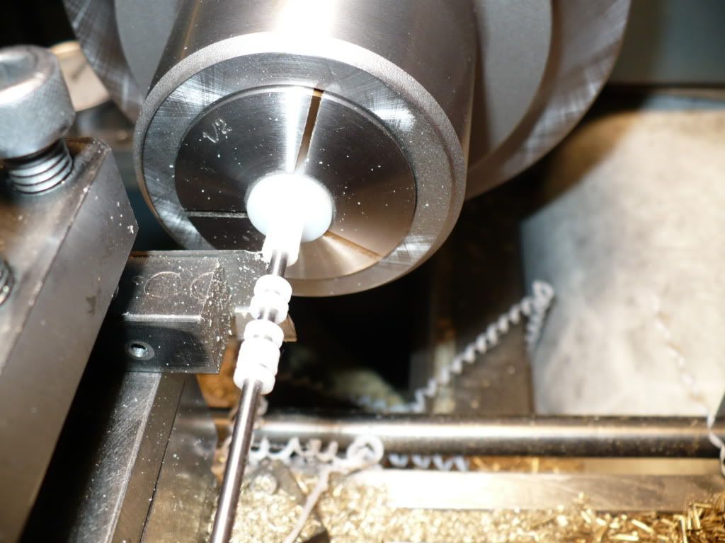
#284 To part off the rather small and thin Delrin washers I used a Razor blade as a cut-off tool. A small diameter rod mounted in the tail stock chuck was used to catch the washers as they were parted off. I used a slightly smaller diameter rod and watched my in-feed by going in to a pre-determined setting on my dial indicator to avoid running into the rod with my cutter. Sure beats bending over to pick one up off the floor.

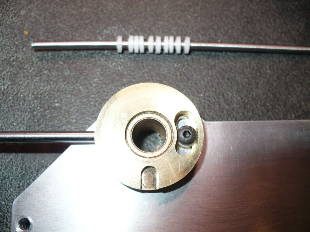
In the picture bellow you can see the Delrin washer sticking out from under the button head screw.

P1050131.jpg


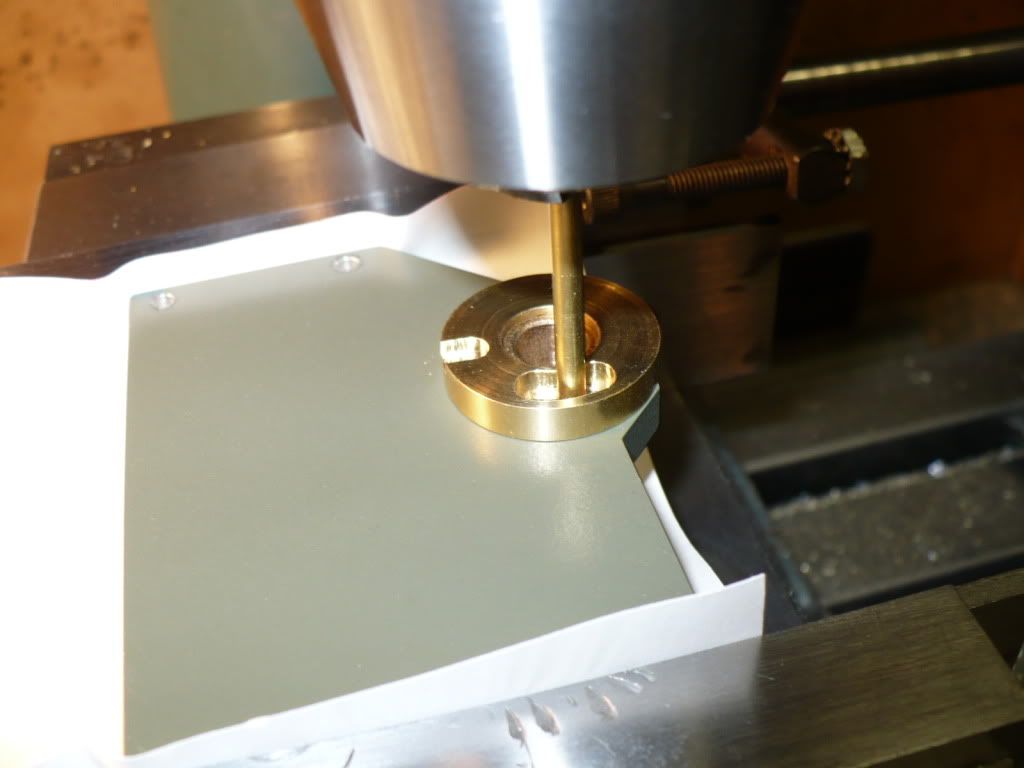
#285 Below I'm drilling and tapping one of the five frame plates. Each plate was set-up individually, and I double check the location by using a .125" rod just to be sure. Wrecking a frame plate at this stage of the project would have been too much to bear.

P1050132.jpg


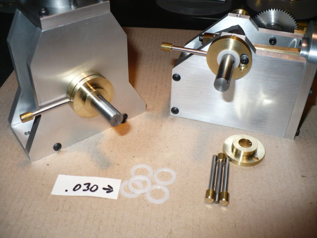
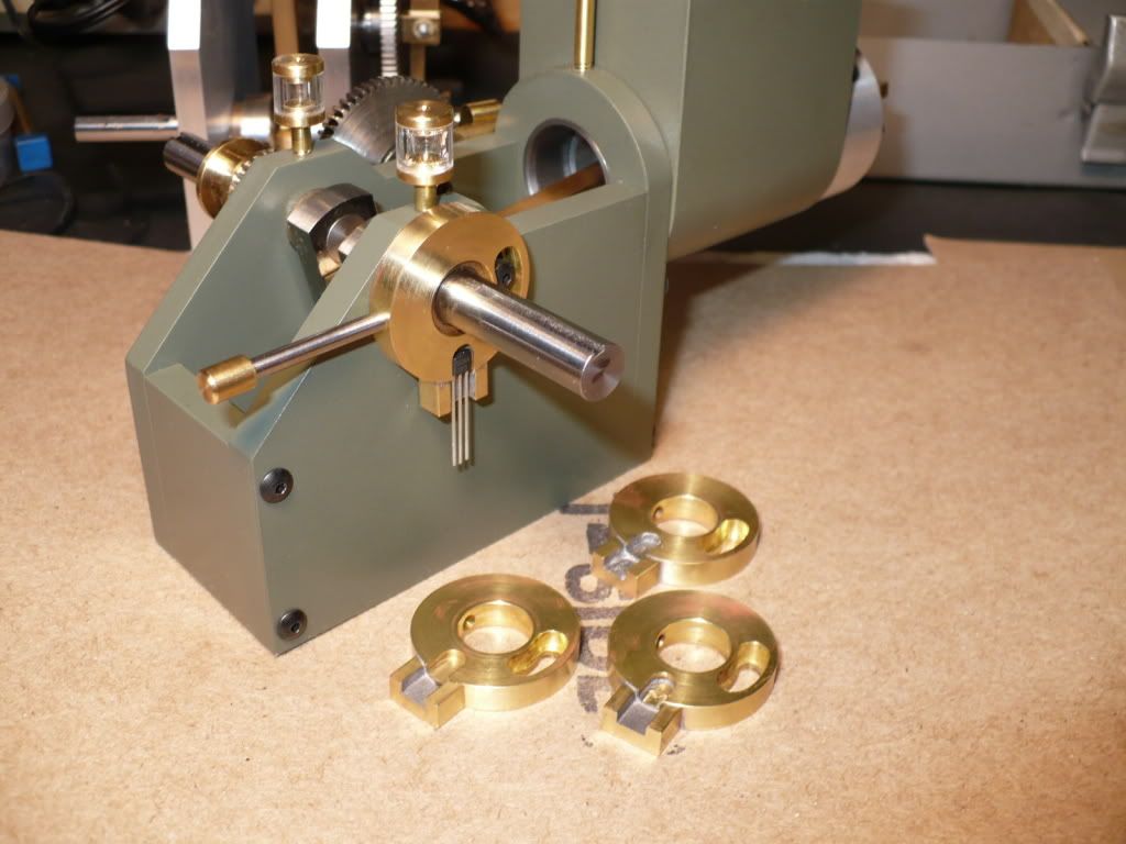
#286 I decided to try out my idea of using a spacer to gap the magnet away from the sensor. This will eliminate fiddling with the air gap space while adjusting the magnets position relative to the crank shaft.

I also made up the adjustment rods using drill rod with a brass barrel style end. I decided not to use knurling since its not needed and its absence affords a clean and simple look. When the flywheels are added to the engines, the rather long appearance of the adjustment rods will disappear.

P1050136.jpg


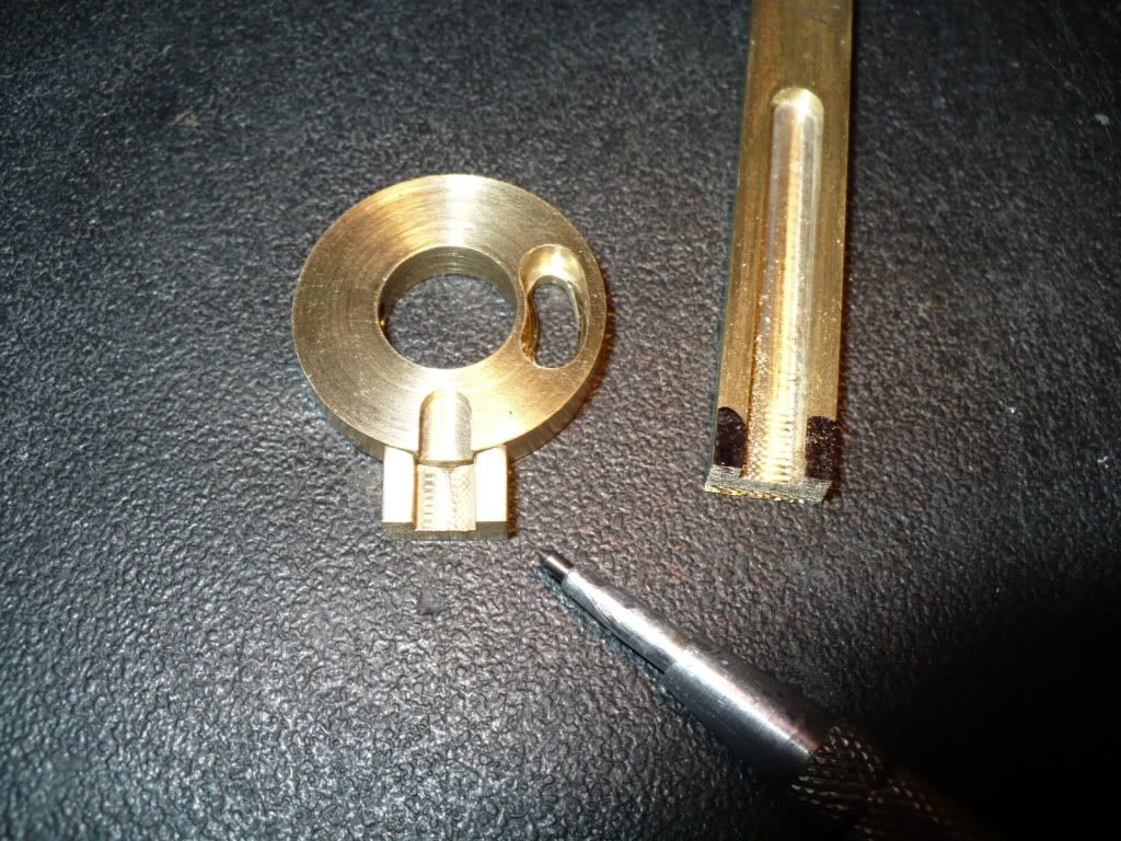
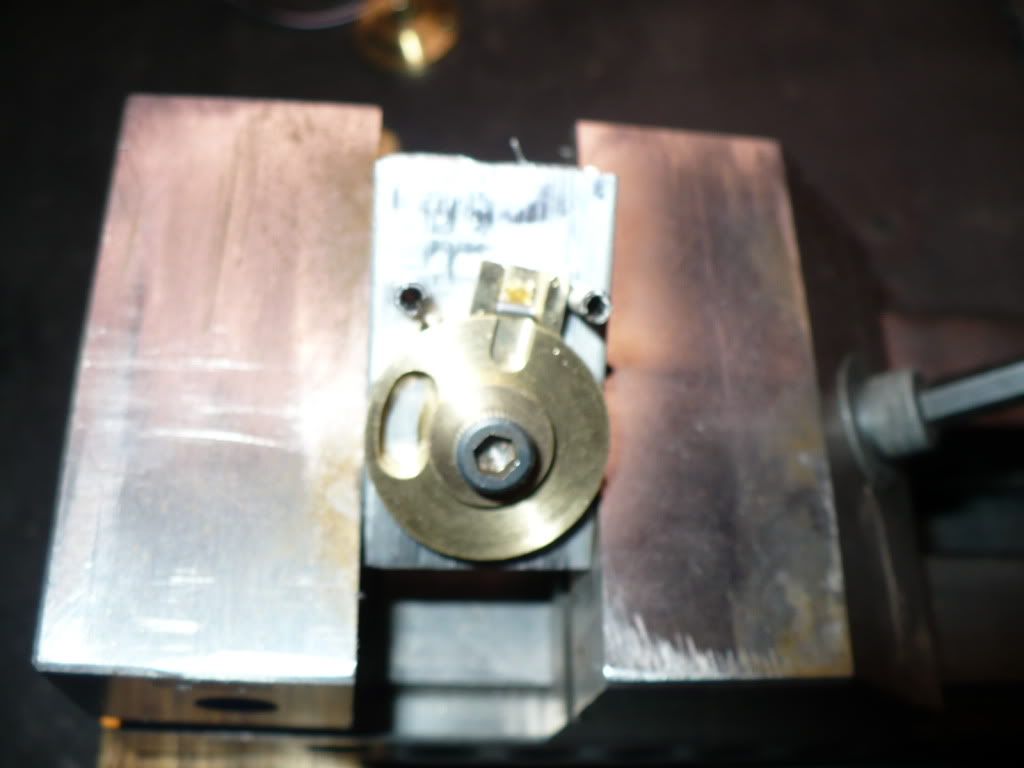
#287 I became increasingly concerned with the possibility of the Hall sensors becoming damaged by flexing-pressure applied to their pins during adjustments and handling. I mentioned this concern and solution in a previous reply on this thread. I didn't want to make up new discs, so I came up with a modification to achieve the same result by making the discs a build up of two parts.

I milled up some brass stock with a wider and deeper grove to accommodate insulated wires. The wires will be fixed in position with an appropriate potting compound such as silicone or epoxy. This will help eliminate the possibility of sensor damage.

P1050140.jpg


#288 I used the fixture that I made previously for the mill work on the sensor disc, as a soldering fixture. Sorry that the picture came out blurred, but hopefully you can see how it was used.

P1050143.jpg


#289 Below you can see the completed modifications. Two are already installed plus the three on the cardboard. I placed the solder on the added pieces which caused them to get tinned on the inside. Controlling the flow of solder can be difficult at times. Fortunately once the sensor is set in potting compound this little solder mishap will be out of sight and out of mind.

P1050147.jpg


-MB
 

Latest posts

Back
Top