Henry Ford Engine

Home Model Engine Machinist Forum

Help Support Home Model Engine Machinist Forum:

This site may earn a commission from merchant affiliate links, including eBay, Amazon, and others.
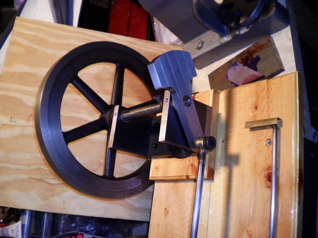
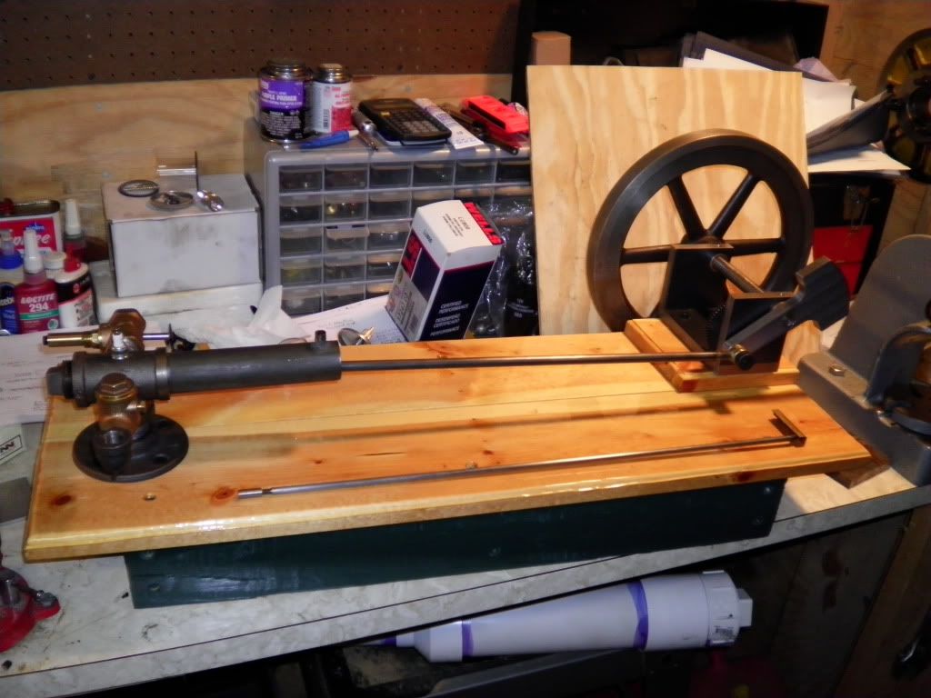
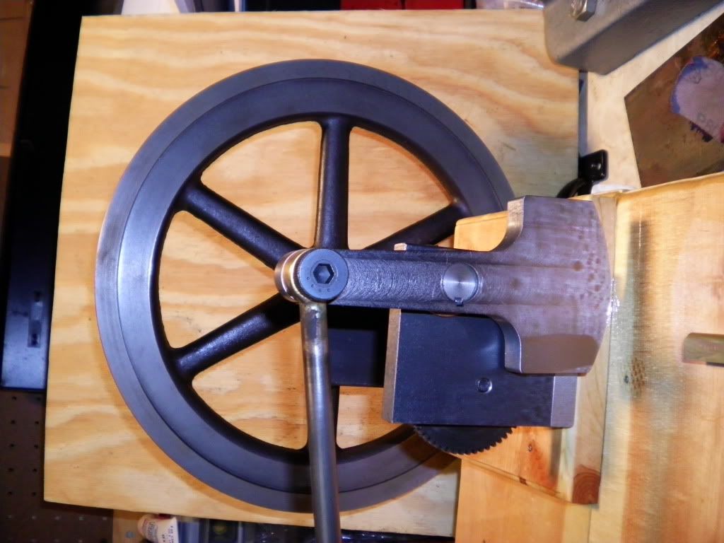
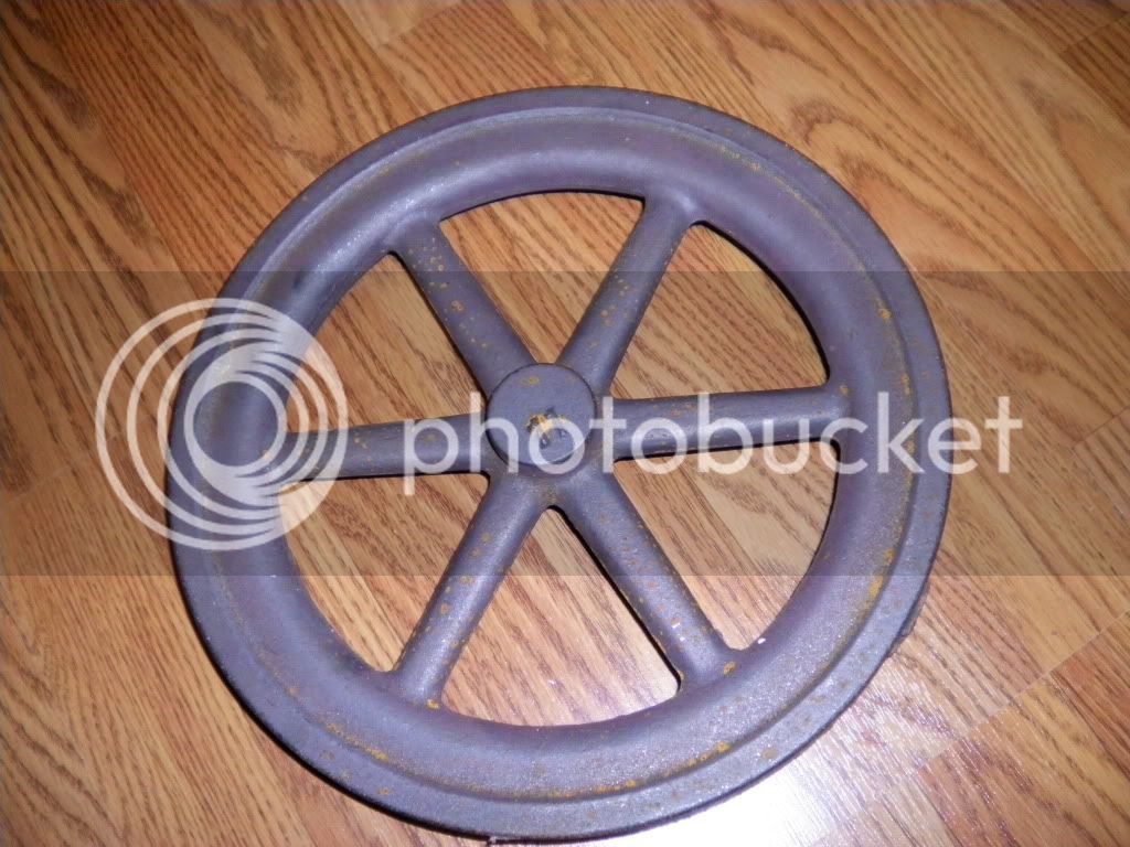
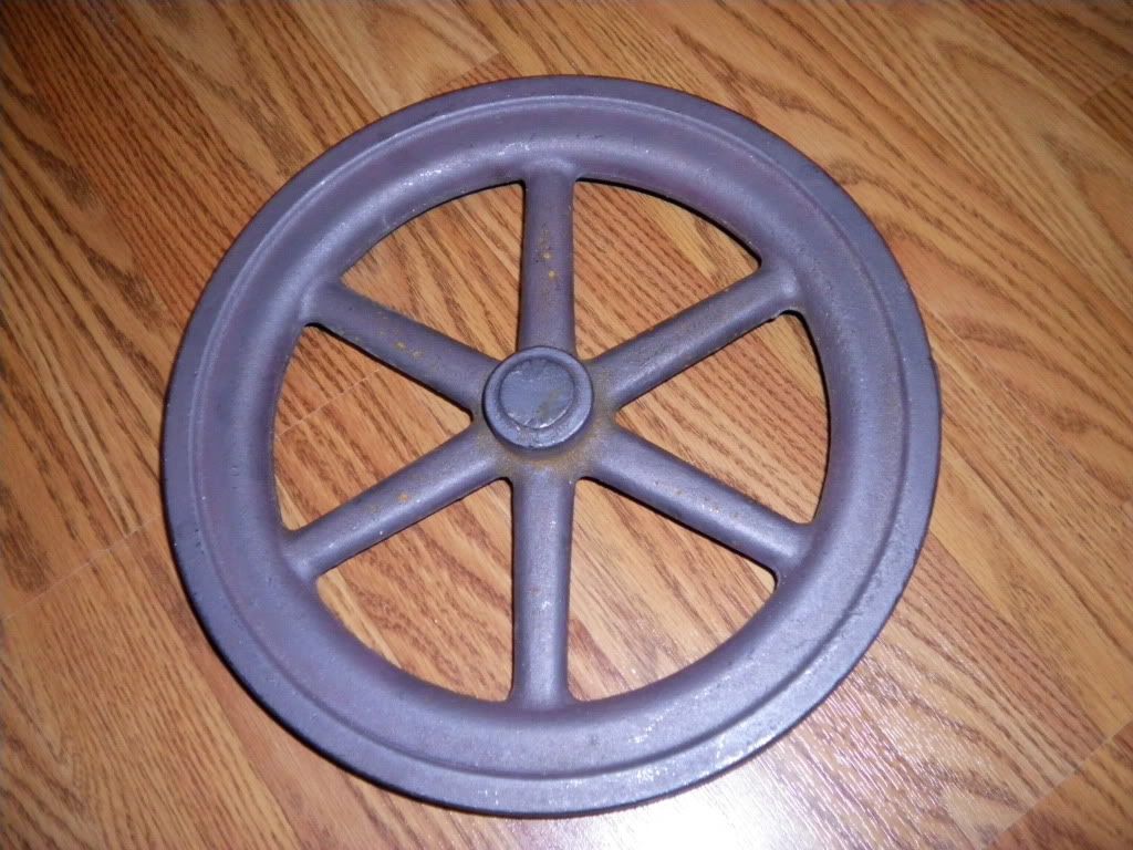
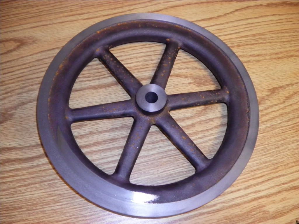
Here are pictures of the flywheel casting from Martin Model and Casting. I never machined anything this large before so hopefully I didn't screw it up. I turned the outside diamter to clean, faced it, drilled & bored to 0.625". I don't like how it cleaned up nice on one end of the flywheel and it kept cutting further down towards the center. I have the runout within .002 to .003 thousandths and don't want to risk taking any more material off.

I suppose I could mask the outer face and paint the spokes and it won't be as noticable. I'm just not happy with how the face came out.

flywheelcasting002.jpg


flywheelcasting001.jpg


flywheelcasting003.jpg


Chris
 
framealmostcomplete.jpg


This picture is not much different than the one above except it has been line reamed...and the crankshaft actually fit!!! And it spins freely!!!!!

Very exiting.

Chris
 
Here is the picture of the completed frame. I keyed the shaft and installed the gears. I also added a #3-48 set screw to the small gear.

The remaining pictures show the progress of the crank. I wanted to teach myself how to use the Prototrak and in a couple of days I finally got the program to work correctly. Now I have to mill off the rest. The next time I make this I'm going to fasten the crank down to a fixture plate so I don't have so much milling to do. Now that I can use the Prototrak I can make all kinds of crazy parts.

Next week will be the cam.

Chris

crank-5.jpg


crank-4.jpg


crank-2.jpg


framecompleted.jpg


crank-1.jpg


crank-3.jpg
 
Having some trouble with the wood base. Actually with the center height between the combustion chamber and the crank frame. It seems that I need to bring the combustion chamber down about a 1/2" for everything to line up properly. I can't fit the wood base in my mill but I guess I could ass a 1/2" spacer plate under the crank frame.

Has anyone else run into this issue when building the Henry Ford stationary engine? If so, what was your fix?

Thanks,

Chris
 
Chris, an idea would be to lower the combustion chamber.
Find another nipple that will thread in 1/2" more than the one you got.
Chase the nipple threads you have to get them to screw in further.
Tap the floor flange and or tee more to get them to screw in further.

Built a half size Ford engine using 1/2" tee. A problem had with the wood base was the crank frame and the floor flange both worked in the wood and rocked back and forth. Made steel plates and inlet in the wood base and drilled and tapped. Then bolted the top pieces to this. This solved my problem, you might not have this problem if using hardwood, my base was a softer wood, an old 2 by 6.


vascon2196 said:
Having some trouble with the wood base. Actually with the center height between the combustion chamber and the crank frame. It seems that I need to bring the combustion chamber down about a 1/2" for everything to line up properly. I can't fit the wood base in my mill but I guess I could ass a 1/2" spacer plate under the crank frame.

Has anyone else run into this issue when building the Henry Ford stationary engine? If so, what was your fix?

Thanks,

Chris
 
vascon2196 said:
Having some trouble with the wood base. Actually with the center height between the combustion chamber and the crank frame. It seems that I need to bring the combustion chamber down about a 1/2" for everything to line up properly. I can't fit the wood base in my mill but I guess I could ass a 1/2" spacer plate under the crank frame.

Has anyone else run into this issue when building the Henry Ford stationary engine? If so, what was your fix?

Thanks,
Chris

I had the same problem on my plumbing parts engine. I put a 1/2" spacer block under the crankshaft assembly. Worked fine.

ae7250cc.jpg


Chuck
 
Thank you Chuck. This is exactly what I am going to do tonight.

Another issue I have is that the cylinder is angled up slightly which doesn't help. I have a feeling the floor flange is uneven and that is being transferred up through the combustion assembly.

Thanks again Chuck.

Chris
 
vascon2196 said:
Thank you Chuck. This is exactly what I am going to do tonight.

Another issue I have is that the cylinder is angled up slightly which doesn't help. I have a feeling the floor flange is uneven and that is being transferred up through the combustion assembly.

Thanks again Chuck.

Chris

Yeah, those floor flanges are pretty rough. I screwed a short length of pipe nipple into mine, then chucked it up in the lathe and faced off the bottom of the flange to get it square and flat. That made everything square and parallel with the base.

Chuck
 
I was able to chase the flange threads a bit and torqued the nipple in a bit more. This helped with the height difference between the combustion chamber and crank assembly. I built a robust wooden base and coated the top with six coats of polyurethane. I used brass inserts to thread into the wood and then fastened everything down with socket cap screws. I still have to make the pusher rod support brackets, buy a 12V battery, on-off switch, and continue fumbling around with the oiler.

I cannot solder AT ALL, and after several attempts I am making a new stem for the oiler.

Here are some pictures of what I have so far.

Chris

FORDENGINE12-18-2010004.jpg


[IMG
FORDENGINE12-18-2010002.jpg
]
http://i761.photobucket.com/albums/xx257/vascon2196/Henry%20Ford%20Engine/FORDENGINE12-18-2010003.jpg[/IMG]

FORDENGINE12-18-2010005.jpg


FORDENGINE12-18-2010001.jpg


Coming along nicely Chris Thm:

Regards, Arnold
 
Does anyone have a good picture of the electrics for this engine. I am a mechanical guy and get nervous around this stuff. I just purchased a 12V battery, I have the 5-wire relay, and ignition coil. I do not have an "on-off" switch.

I don't know if I need a single pole or double pole or what?

There was an electrical schematic with the plans but it might as well been in chinese.

Thanks for any help.

Chris
 
The more I read, the more I want to build a henry ford engine too. I would probably like to make a scaled down version. I have several questions that would probably be best answered by purchasing the plans but until then: on the full scale version what is the diameter of the flywheel? The bore diameter and length of the stroke? I am assuming bore is 1" and wondering how small this engine could be scaled to. Does any one have any guess as to the compression ratio? I would think it is fairly low. When chuck said he likes to start his a lot that makes me want one even more. John ;D
 
Brian Rupnow said:
Are you running points and condenser?---if so, send me your phone number---brian

Hi Brian,

I don't think so. The plans call out for a 12V battery, relay, on-off switch, and ignition coil. I'm pretty sure I can figure it out if I stare at videos and pictures long enough but I prefer details.

Thanks,

Chris
 
jct842 said:
The more I read, the more I want to build a henry ford engine too. I would probably like to make a scaled down version. I have several questions that would probably be best answered by purchasing the plans but until then: on the full scale version what is the diameter of the flywheel? The bore diameter and length of the stroke? I am assuming bore is 1" and wondering how small this engine could be scaled to. Does any one have any guess as to the compression ratio? I would think it is fairly low. When chuck said he likes to start his a lot that makes me want one even more. John ;D

Off the top of my head I think the flywheel was 13 or 14 inches in diameter. The plans are in my shop which is 100ft into the woods covered in 8 inches of snow. :mad:

The bore diameter I think was 1-1/8" diameter with a 21 inch stroke.

Chris
 
I just looked at the second link in reply #2, and he is running with a model T "trembler" coil, which is a totally different animal from what you have. And even it has a cam and a set of breaker points. With a coil like you have, you need a set of points which are opened and closed by a cam to "break the circuit" in the primary coil windings, in order to induce a high voltage in the secondary windings of the coil to "fire" the sparkplug. And if you want the points to last longer than 20 minutes, you will have to run a condenser with the points to prevent the backsurge of current induced in the primary windings by the collapse of the field in the secondary windings from burning the points up.
 
jct842 said:
The more I read, the more I want to build a henry ford engine too. I would probably like to make a scaled down version. I have several questions that would probably be best answered by purchasing the plans but until then: on the full scale version what is the diameter of the flywheel? The bore diameter and length of the stroke? I am assuming bore is 1" and wondering how small this engine could be scaled to. Does any one have any guess as to the compression ratio? I would think it is fairly low. When chuck said he likes to start his a lot that makes me want one even more. John ;D

I originally scaled my engine down to a 5/8" bore and 2" stroke, with a 7.25" flywheel. However, it didn't have enough power so I increased the bore to 7/8" but left the stroke at 2". I used 3/4" plumbing parts.

Chuck
 
Brian Rupnow said:
I just looked at the second link in reply #2, and he is running with a model T "trembler" coil, which is a totally different animal from what you have. And even it has a cam and a set of breaker points. With a coil like you have, you need a set of points which are opened and closed by a cam to "break the circuit" in the primary coil windings, in order to induce a high voltage in the secondary windings of the coil to "fire" the sparkplug. And if you want the points to last longer than 20 minutes, you will have to run a condenser with the points to prevent the backsurge of current induced in the primary windings by the collapse of the field in the secondary windings from burning the points up.

Can I buy a condenser from McMaster Carr?

Chris
 
Since I don't have the specifics of your engine here in front of me, I can only offer this advise. Any 12 volt condenser will do, but if you want part numbers, go to my thread on building the Kerzel engine and read it through---I have a couple of good shots of the points and condenser, where I installed them on the engine, and the part numbers of the points and condenser. Points don't generally care to much whether its 6 volts or 12 volts going thru them. I can phone you and tell you how to hook it up, or do a cheap and dirty sketch and email it to you.---Brian
 

Latest posts

Back
Top