Henry Ford Engine

Home Model Engine Machinist Forum

Help Support Home Model Engine Machinist Forum:

This site may earn a commission from merchant affiliate links, including eBay, Amazon, and others.

vascon2196

Well-Known Member
Joined
Oct 2, 2009
Messages
1,026
Reaction score
312
Hello everyone...I am two weeks into building Henry Ford's first stationary I.C. engine. I've always wanted to build a I.C. engine and decided to build Henry's first and go from there. I am going to try and stay as true to the original design as possible changing only a couple of things. I am purchasing a nice flywheel casting instead of an old lathe handwheel and the ignition source will be an NGK-Cm6 spark plug instead of the homemade tungsten/brass version that Ford used.

Here are some pictures I have taken over the past two weeks.

Hope you like it.

Chris

ford002.jpg

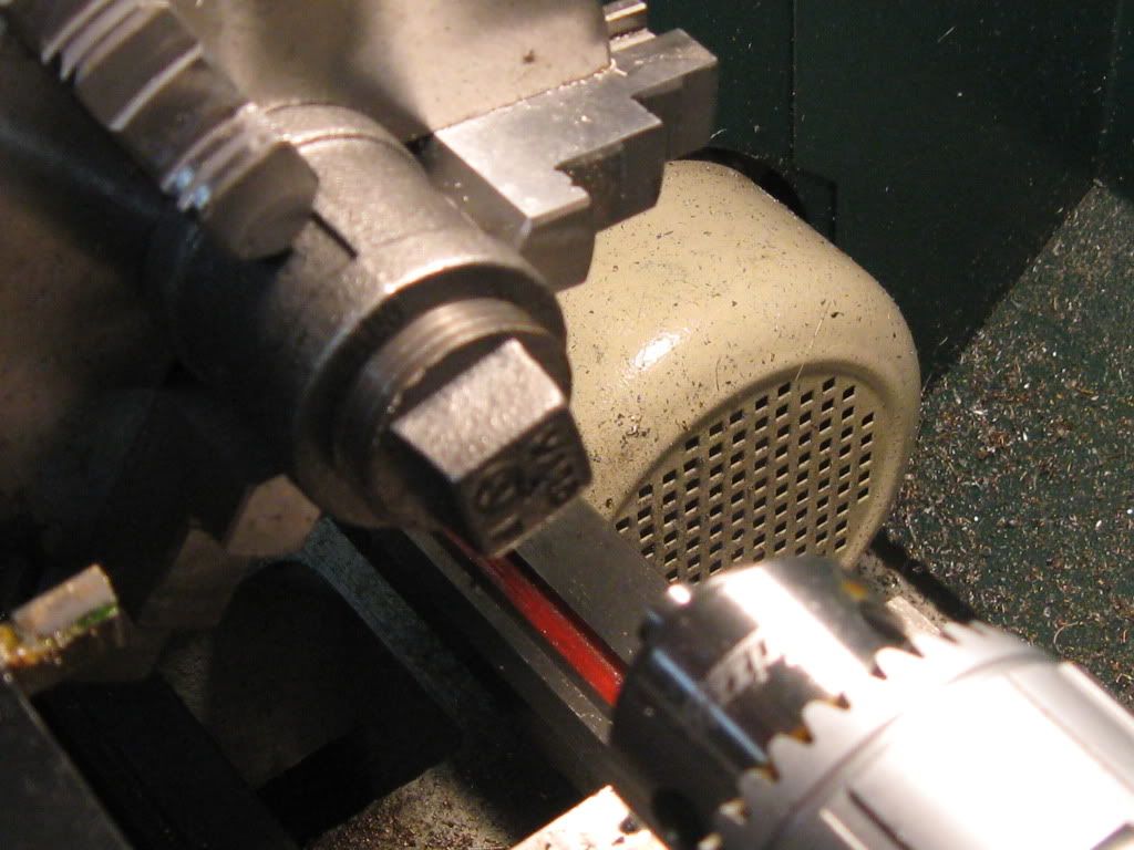
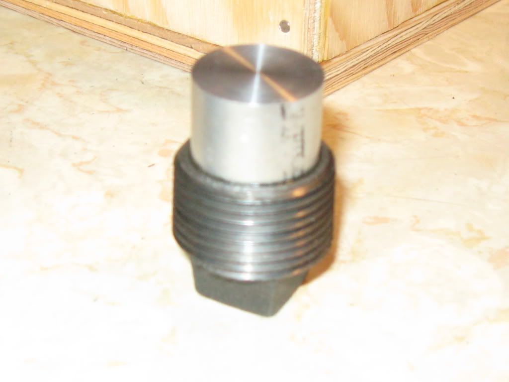
Centering the 1" pipe plug to help establish cylinder height

ford004.jpg

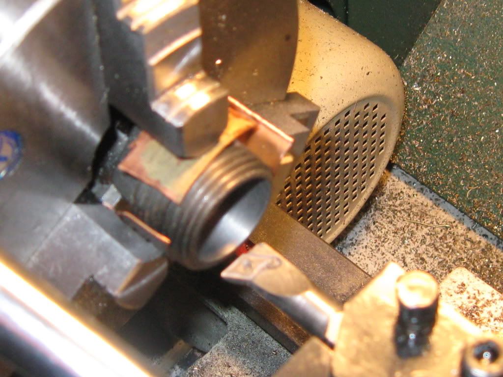
Boring back of 1" pipe plug to accept an aluminum plug

1inpipenippleboredforfreezeplug.jpg

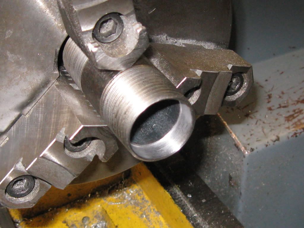
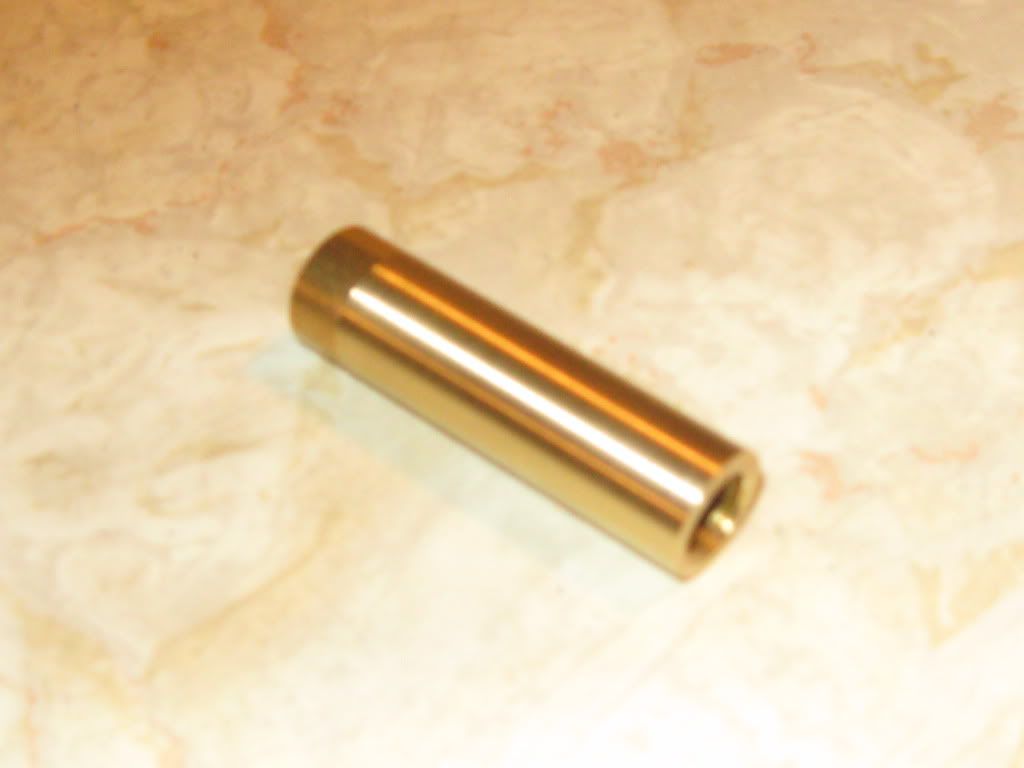
Boring one end of 1" pipe nipple to accept an automotive freeze plug

1inpipenipplewithfreezepluginstalle.jpg

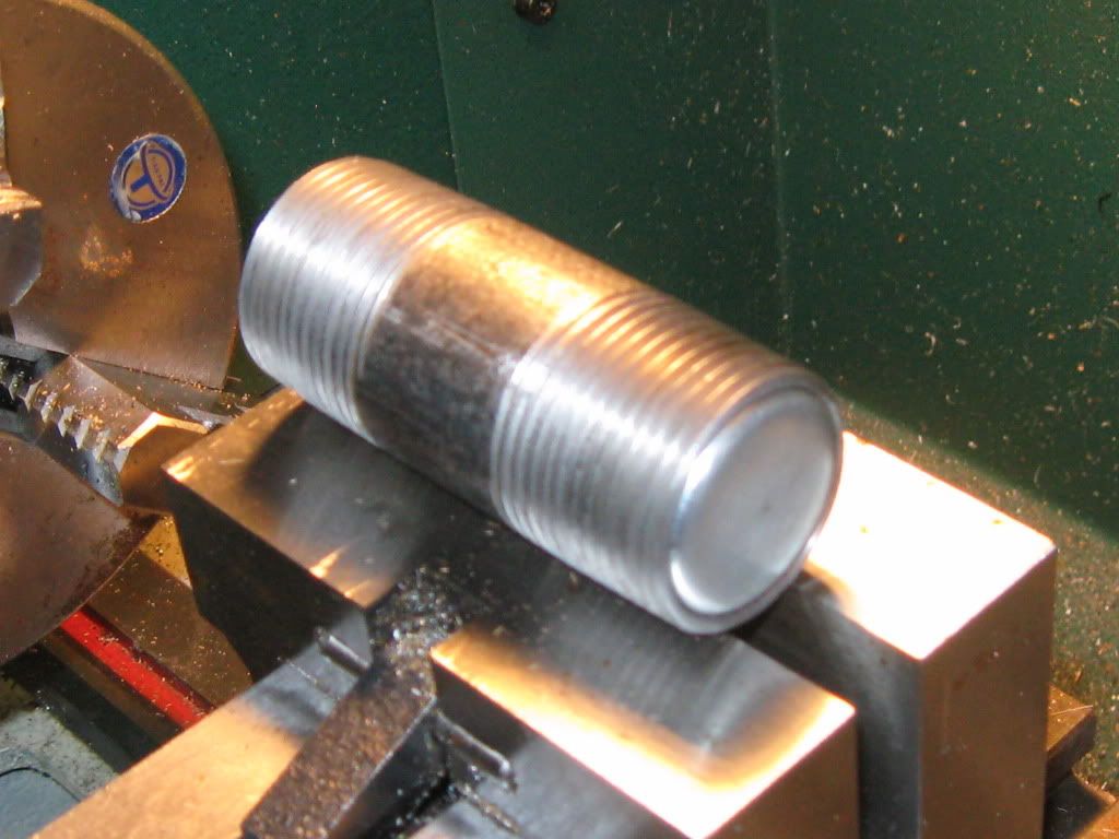
Finished 1" pipe nipple with freeze plug loc-tited in

1inpipeteeboredforcylinder.jpg

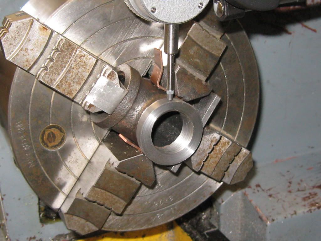
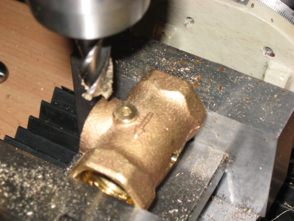
Centering 1" pipe tee in four-jaw and boring out for cylinder

ford001.jpg

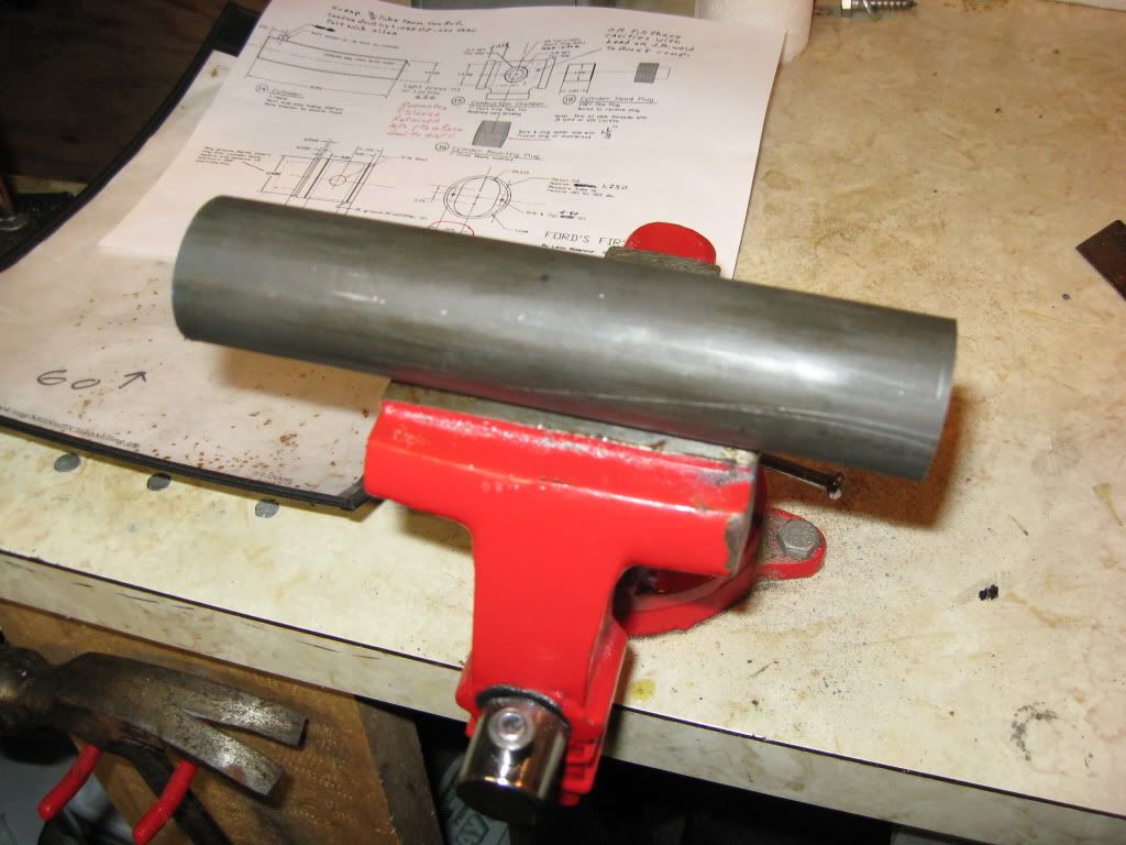
Cylinder cut oversize and ready for facing to finished length

pipetapstapdrills.jpg

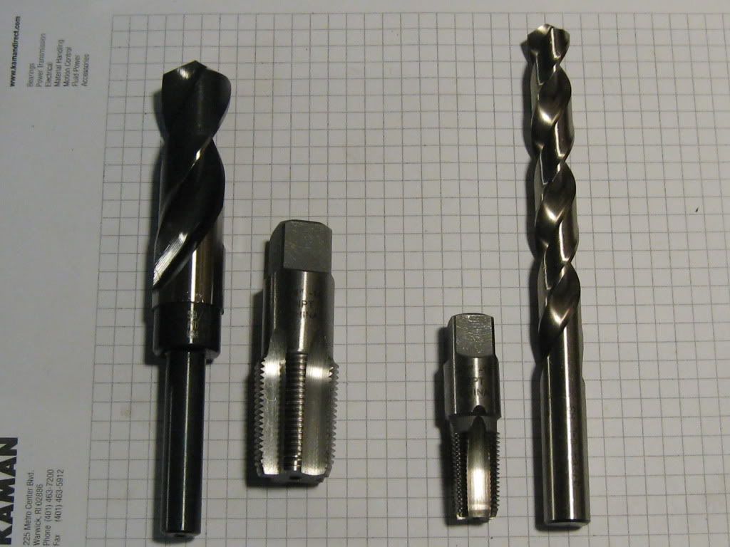
3/4" NPT and 3/8" NPT pipe taps and (expensive) tap drills
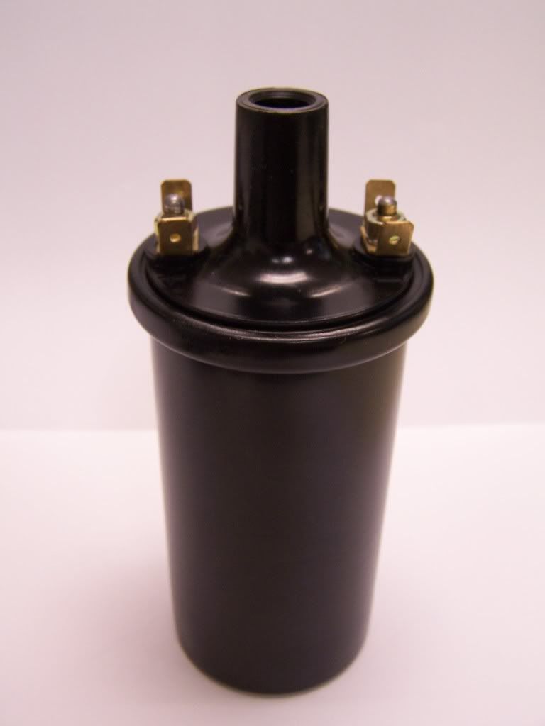
12VIGNITIONCOIL.jpg

12V ignition coil

stopwastevalve-1.jpg

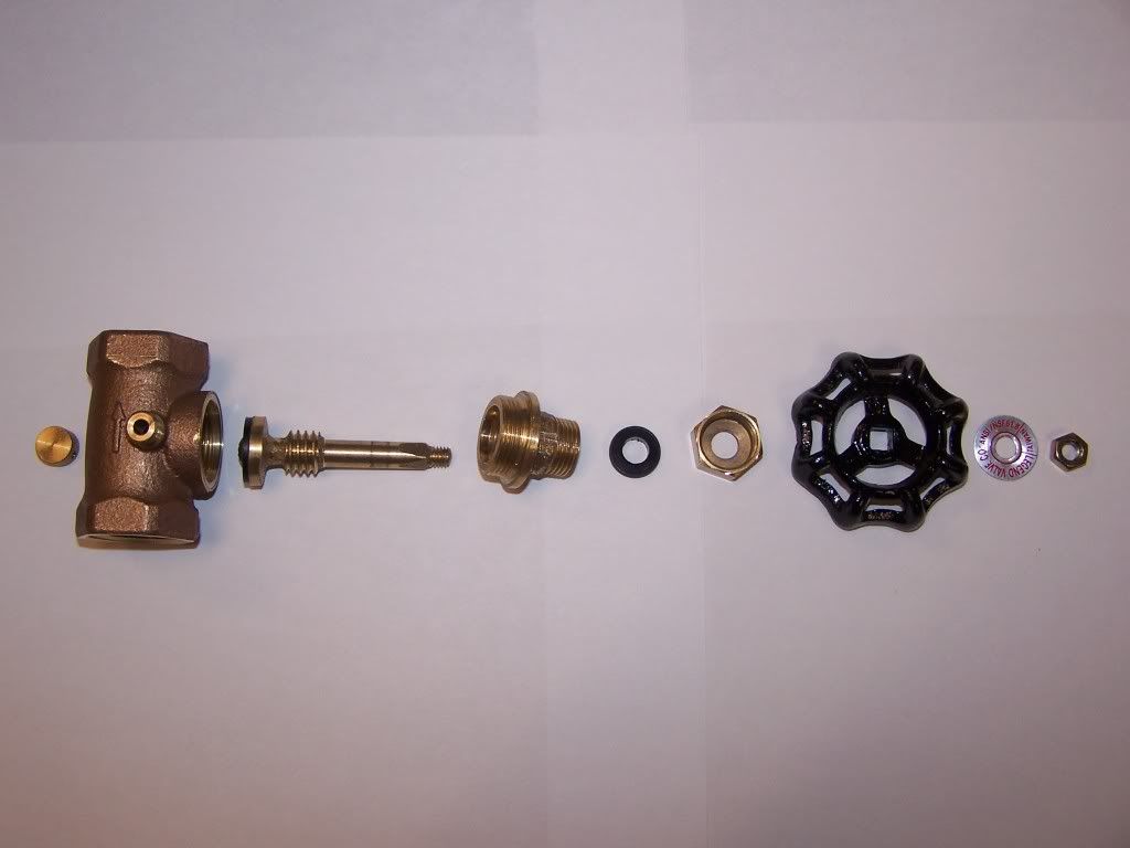
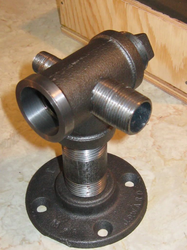
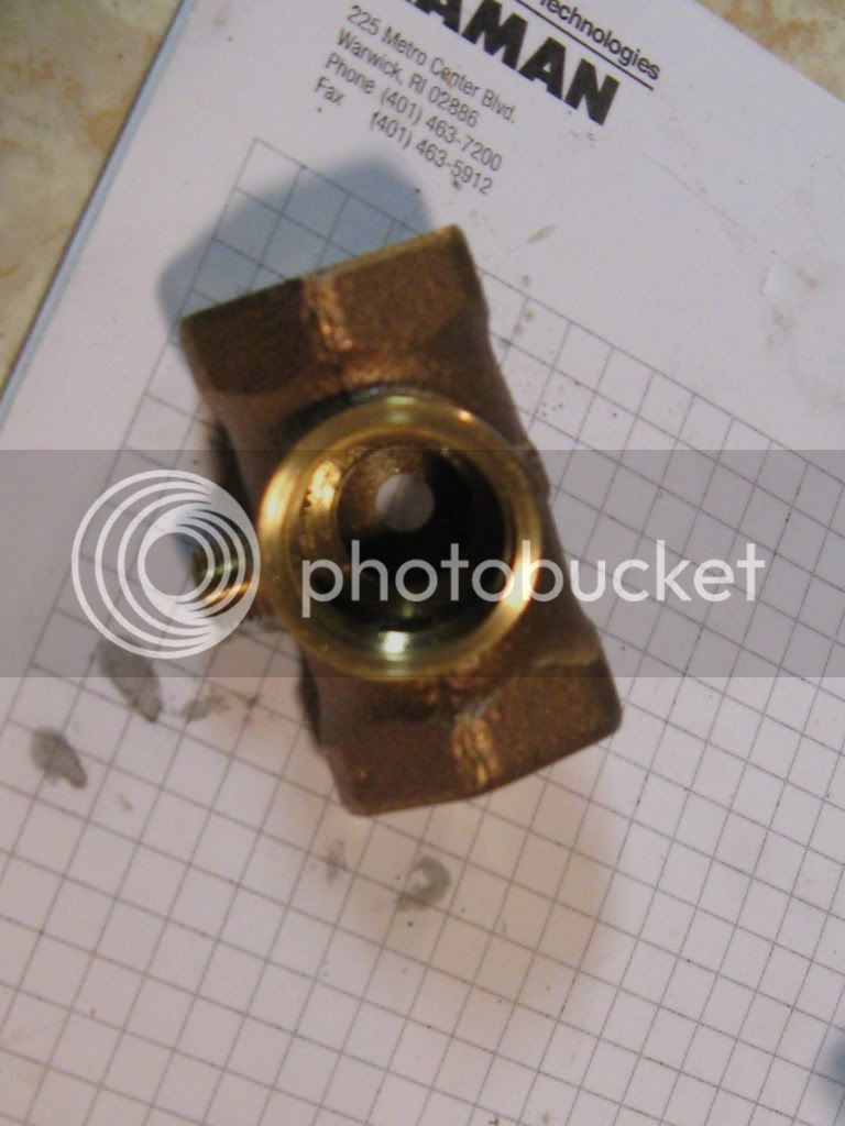
Globe valve / stop and waste valve dismantled

stopwastevalve-2.jpg

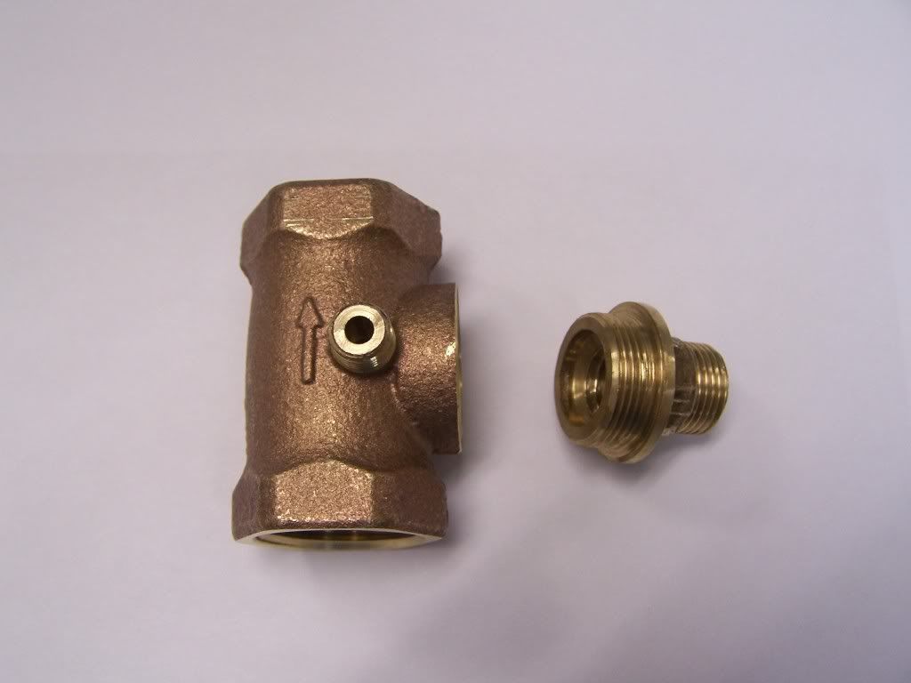
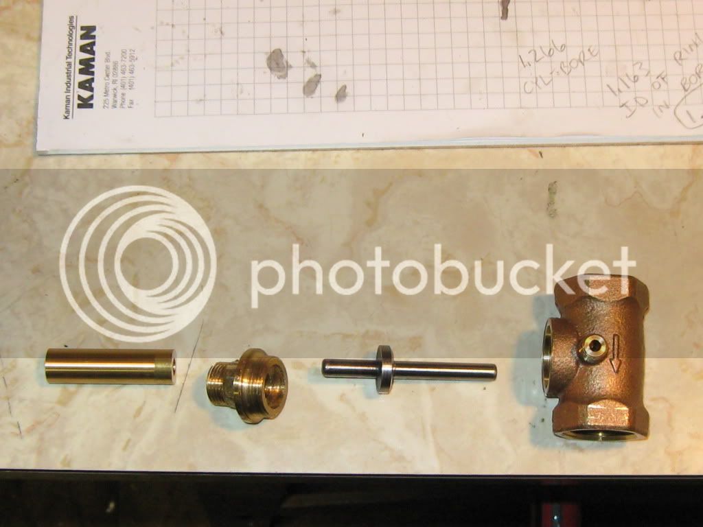
Valve body and valve bonnet ready for modifications

fordeng2.jpg

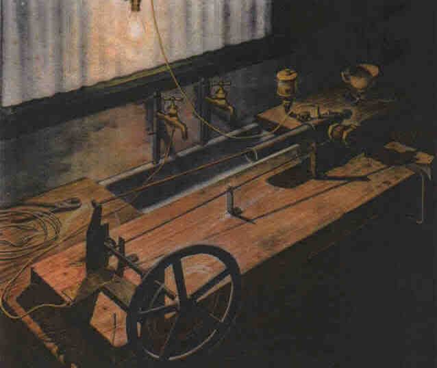
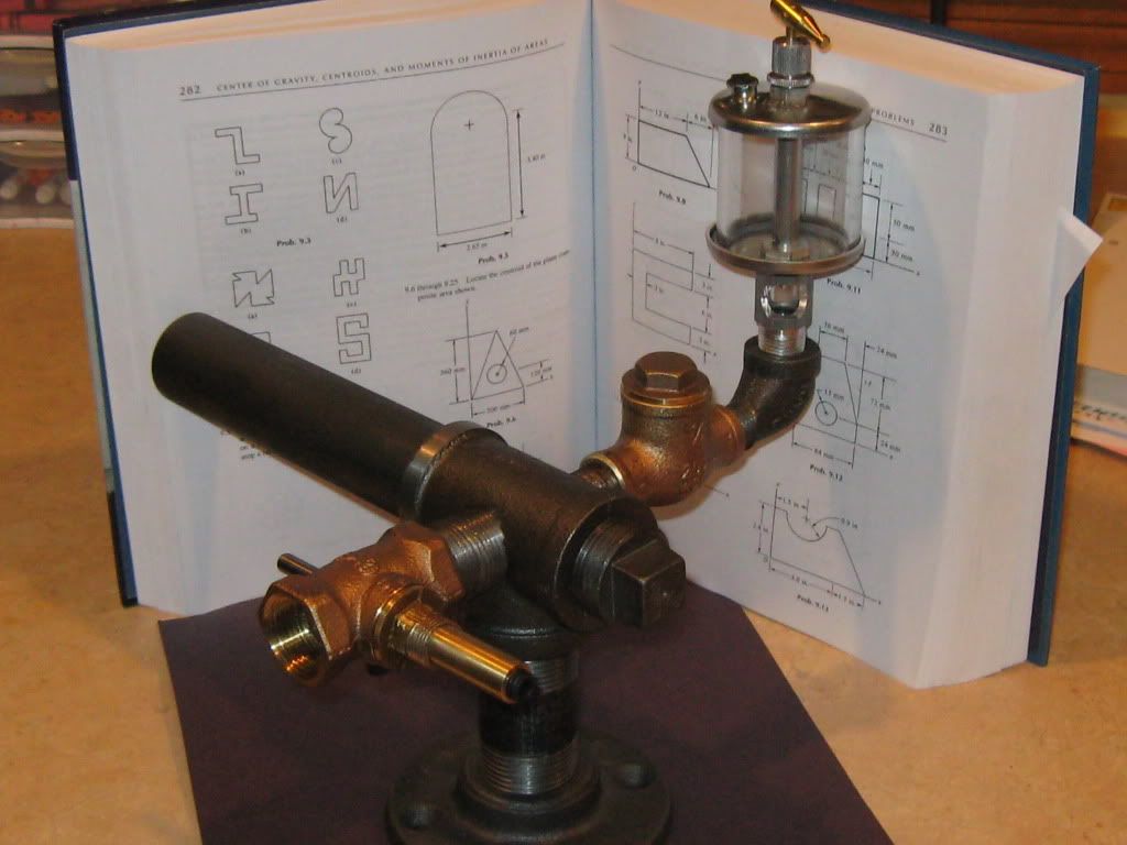
Here is the original engine I am going to TRY and replicate
 
It is 2-stroke, or 4-stroke?
Is there any more pics of the original?
Did henry build this himself?
Where did you find plans?
Is this considered a Ford engine?

Sorry for all the questions, but I am verry interested in this build.
kel
 
Kel,

I believe it is a 2-stroke. This engine was built by Henry Ford himself and run for the first time in his kitchen. The link I have attached will explain where to purchase the plans.

Here is a link to a website by someone who has built the engine. There are some great pictures attached along with where to purchase the plans. I also purchased the plans from Leon Ridenour in TN (865-584-9759) which included the plans, an instructional DVD, piston ring, and 2-gasoline screens all for $30.00.

http://www.oldengine.org/members/jbailey/frsteng.htm

Here is another link with more great pictures and a story of the engine.

http://nbutterfield.com/e.aspx


I hope this helped!

Chris
 
Thanks Chris.

Cool stuff.

kel
 
Actually, it's a 4 stroke. The cam turns at half the speed of the crankshaft and opens the exhaust valve every other crankshaft revolution. The intake valve is vacuum operated by the piston on the intake stroke.

Chuck
 
Here are some more pictures. Sorry for the lousy pictures...it's an old camera.

1pipeplugwithaluminumslugloc-tited.jpg

1" pipe plug with an aluminum slug loc-tited in place

valveguidecomplete.jpg

Completed valve guide

valvewithoversizediscpressedon.jpg

Valve rough turned and waiting for silver solder

dry-fittingthecombustionchambertoge.jpg

Having fun dry fitting everything together
 
vascon2196 said:
Here are some more pictures. Sorry for the lousy pictures...it's an old camera.

Oh sure, blame it on the equipment..... :big: :big:


BC1
Jim
 
An old friend once told me..."a good craftsman never blames his tools".

It's so true.

But that camera.......ugh... :p
 
It's been a while...my tooling inventory just isn't quite their yet. This project has cost a lot more than I thought but at least I have aquired some great tools that I can use on future projects.

Here are some of the latest build pictures.

exhaustvalvealmostfinished.jpg

Exhaust valve nearly complete

millingoffthreadedbossonstopwasteva.jpg

Milling off drain boss

sub-assemblycomingtogether.jpg

Exhaust valve sub-assembly coming together

Tonight I will be completing the exhaust valve sub-assembly by silver soldering the valve guide and adding the spring
 
That's coming along very well Chris Thm:

Regards, Arnold
 
dryfittingthecombustionchamber.jpg

Dry fitting the combustion chamber, intake, and exhaust

The piston is nearly complete.

The next big item will be the steel frame.

Chris
 
Chris, I'm following this build with a lot of interest. I am a total novice at building something that actually runs, although I've been messing around with doll house scale static models for some time, and still pretty novice at that, only a drill press for machine work. Finally got a lathe and eventually a mill drill, now trying to learn how to use them. I should have paid more attention in high school shop. Lately, I have found this web site and and have been pouring thru it. I'm finally thinking there is a spec of light at the end of the tunnel.
I decided to build a half scale Henry Ford, without plans, after I saw an article in Gas Engine Mag. Looked simple, "any fool can build this" I thought, and I really got fooled. Started about a year and a half ago and finally got it to run last fall. Got thru most of it on second or third tries. The only thing I gave up on was the exhaust valve. After ruining 4 globe valves I beat the hell out of my final try with a 10" adjustable wrench and ruined the cylinder in the process. I finally ended up making a crude valve cage housed in a 1/4" tee, made an entirely new cylinder and piston, this time it worked.
At any rate, I'm still very curious as to how you get all the pieces of this rather uncomplicated looking valve to line up. Do you have any pictures showing more details of it? I'm missing the boat here.
Thanks, GUS
 
Gus....thanks for your interest in this build. You should post some pictures of the scaled version...I'm sure others (including myself) would be interested in seeing it.

As for lining up the exhaust valve: I basically followed the instructions on the plans I purchased which also came with an instructional DVD on how to build this engine. First I took the original globe valve apart, leveled the valve body in the milling machine vise, and centered the machine spindle using the valve seat bore. For me this was the hardest part. Then I drilled and reamed a 1/4" hole through. Then I bored through the original valve seat with a 5/8" end mill. Then I torqued the valve bonnet in place, marked it, and using a 1/2" end mill....bored into the bonnet leaving a minimum shoulder to solder on the valve stem guide. All this was done without moving the globe valve.

When I have time, I will put a drawing together and post it. (hope this helps for now)

Chris
 
Chris, that pretty much explains my failures. I started on the valve bonnet and guide and tried to use the guide as a drill guide to bore thru the bottom of the valve. Every time the drill wandered off leaving the holes out of alignment. I used the original seat, which lined up pretty good, but had to clearance drill the bottom hole. Two of the valves would seal in a vertical position, but not horizontally. I also had to use a check ball in the intake, as I couldn't find a reasonably sized flapper valve.
Thanks
GUS


100_0653.JPG
 
Very cool Gus! Did you create a set of plans for this engine? Does it run good?

I like it....nice job.

Chris
 
Sweet project.

I was just reflecting the other day, on my way out of a hardware store, how many plumbing fixtures I've bought in my life without ever having used them for plumbing. In this case I cheated a bit, I was plumbing a compressed air system for the shop, but still, I've never done any domestic plumbing after all that. I've made telescope mounts and all sorts of other odd things, just never moved any water through a pipe.

Good to know Henry Ford made good use of plumbing fixtures too!

Cheers,

BW
 
Chris, no I didn't draw up plans, just a lot of rough sketches. I spent considerable time scaling various pieces from the photos in the magazine article.
And no, I wouldn't call it a good runner, but I'm happy to say it is a runner. It sputters and pops, runs at all different speeds with no coaxing and eventually floods out and dies, but I never had any problem with overheating, probably because of the flooding and maybe the brass body tee wicks off some of the heat. The needle valve I made meters the fuel quite well, but the engine always stalls if I try to lean it out. Best time running was 15 minutes or so. I'd have to say some of the sputtring problem is from the check ball bouncing around. I get much better results running it on Coleman fuel in lieu of gasoline.
I'm just recently playing around making new valves from 1/8 street ells with a valve body pressed in. They are quite simple and seem like they will work. I know that is getting away from the original design, but after reading Ckuck's build and finding that I already did a lot of things different than the original, what the heck.
GUS
BTW, Chuck, if you read this I followed your build, it was great.
 

Latest posts

Back
Top