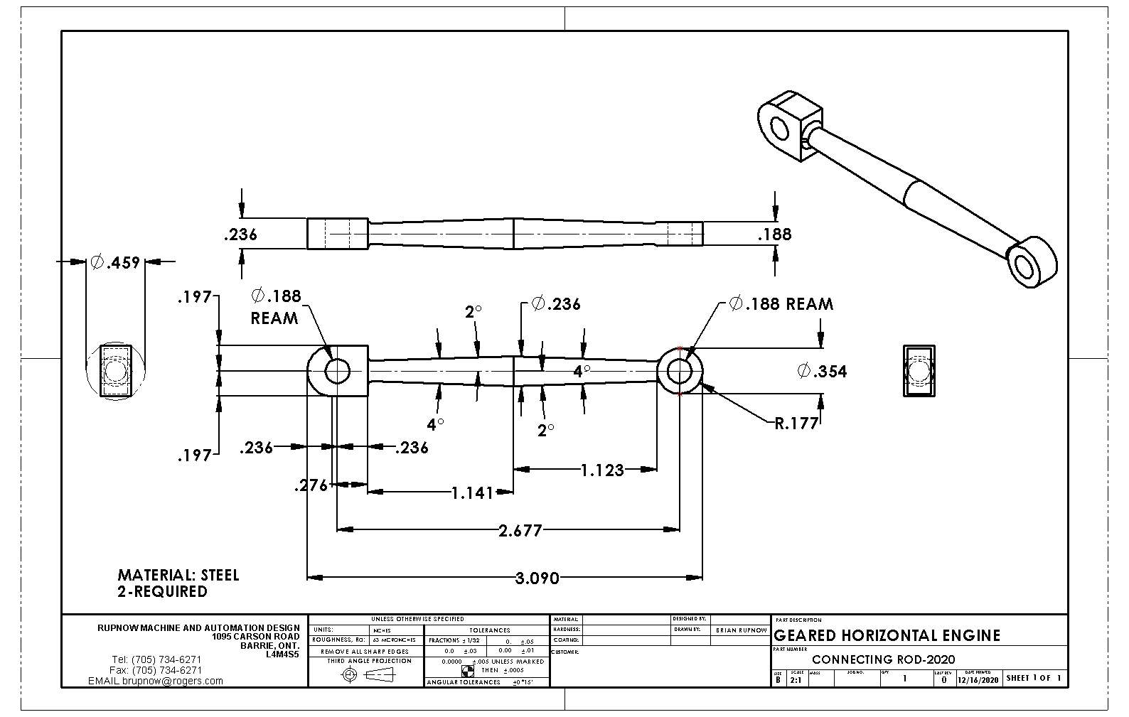
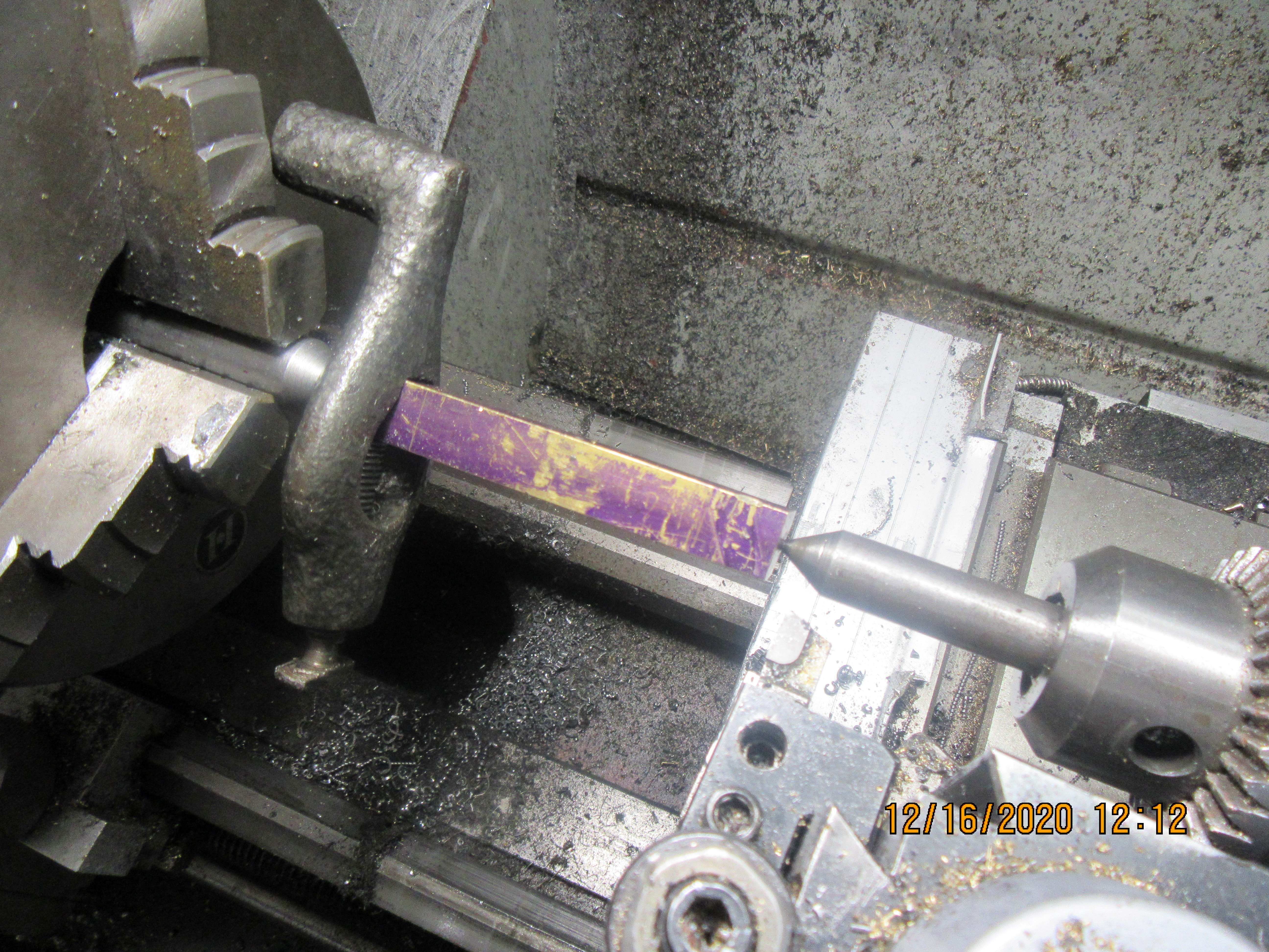
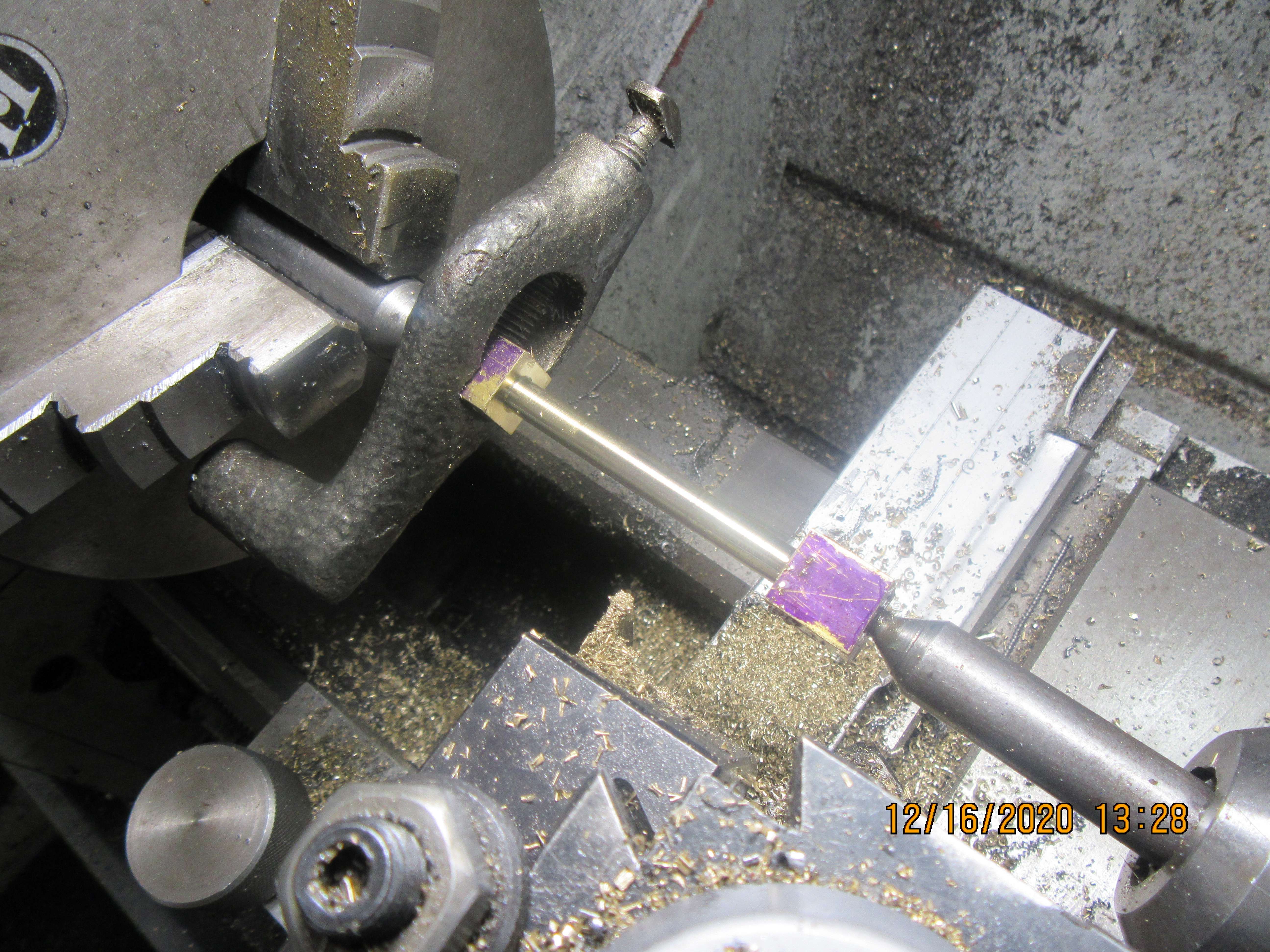
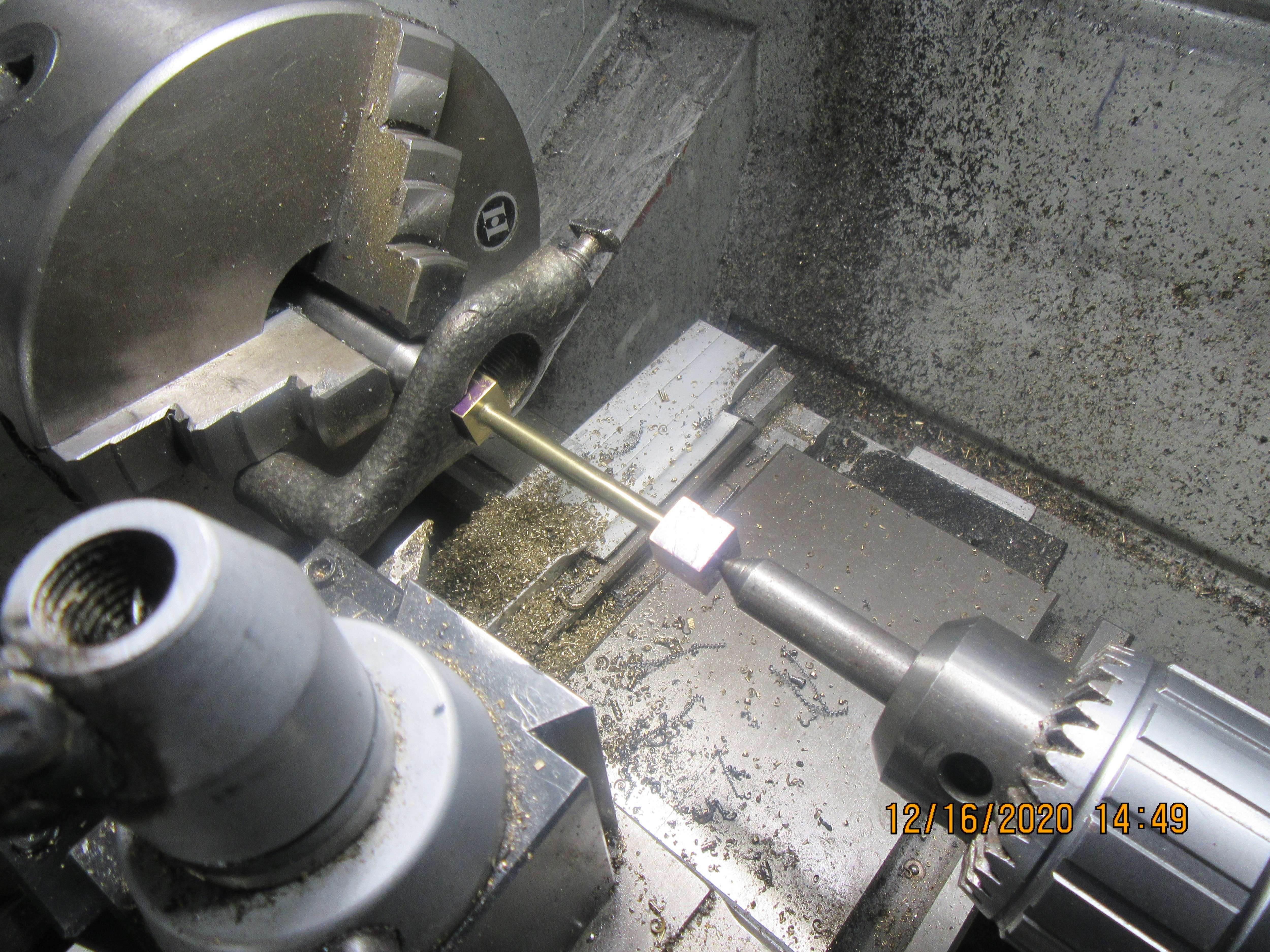
I have a couple of old lathe dogs that hardly ever get used. If this was something super critical, I would remove the chuck and put a dead center into the tapered socket in the end of the spindle, however for what I'm doing, I simply chuck up a piece of cold rolled with the one end turned to the specified angle. The other end is supported by a dead center in the tailstock chuck. I do have a live center, but on short pieces like I am doing here, it takes up too much space. I will put a dab of grease on the end of that tailstock dead center, and the turn the round portion of the conrod down to 0.25" diameter over it's full length. I know that the drawing specs out 0.236" diameter, but I'm going to make it a bit heavier.


 .
.