Elmers #33---Kind of---

Home Model Engine Machinist Forum

Help Support Home Model Engine Machinist Forum:

This site may earn a commission from merchant affiliate links, including eBay, Amazon, and others.
Hi Brian, very nice machining. I like your setup for turning the round bosses on the valve.
gbritnell
 
I think I'm going to have to redo the piston. I had a piece of 1/2" brass stock chucked up in my 3 jaw (it was a perfect fit in the cylinder "as purchased".) I drilled and tapped the center hole for the piston rod, but when I went to put the oill grooves in the outer diameter with the corner of my parting off tool, I noticed it cutting heavier on one side of the brass piston than on the other. I thought "Huh---Thats kind of wierd!" but thought nothing more of it. Now with the end cap fitted to the cylinder, and it having a reamed hole which I know is on center, I've got one heck of a bind---Piston/rod no likeey to slide!!! Oh well, a new piston won't take much.-On the next one I'll start with a piece of 5/8" dia. brass and turn the o.d. to 0.5" and do the center bore all in one set-up.
 
I'd be interested in knowing why you think that happened. Seems odd.

Corner of parting tool eh? Neat idea. I imagine you rotated the tool post for that?
 
If you had a perfect fit before you grooved, then you probably raised a miniscule burr on the edges of the grooves. Polish the piston slightly and it should fit just fine.
 
Yes. I just swung the toolpost 45 degrees. As far as why???---I'm not real sure. could be run-out in my chuck Jaws I suppose. I'll have to do some further investigating.
 
Brian, if you did not machine the outside diameter of your piston to run concentric with the spindles center line on the lathe, then the groove cuts will almost always end up deeper on one side due to the normal run out encountered on most chucks

Did you indicate the outside diameter and get zero run out reading on a full rotation of the work piece? If not, the piece needs to be machined down, and if there isn't enough material you need to use another-larger diameter piece.

Always machine the last finish cuts on the outer diameter of a skirted and/or oil grooved piston LAST to ovoid the problem of an enlarged piston diameter.
Its also important that the outer diameter of a piston is concentric with a tapped piston rod hole. To assure this, the outer diameter must be machined and the piston rod hole must be tapped in ONE set up. In other words, do not disturb or move the piece out and back in the chuck until its finished.

-MB
 
I just chucked the piston rod in my 3 jaw chuck and put a dial indicator on the piston o.d. The runout is only .003" which is about as much as I can get out of my 3-jaw on a good day.--So--go to plan B. The 0.5" dia boss on the inboard cyl cap is a precision fit into the end of the cylinder---I will take .005 off that boss so the cap can "float" a bit, and that should clear up any concentricity issues.
 
Time for a few drawings---Some you will see are identical to Elmers, and some are changed to suit my tooling and material. we'll start with the cylinder end caps--
INBOARDHEAD-33-1.jpg

OUTBOARDHEAD-33-1.jpg


View attachment OUTBOARD HEAD-33.PDF

View attachment INBOARD HEAD-33.PDF
 
I had to go out today so I picked up a 1/16" carbide end mill, and was able to finish machining the valve. Jeez, its tiny!!! Talk about picking fly poop out of pepper!!!!
06endmill001JPG.jpg
 
Brian, I'm glad your found a solution to the piston fit problem. I had a slight binding problem that would go away if I rotated the piston and rod. Since I used all the correct procedures, I couldn't just let it go till I found the source of the problem. It turned out that the die cut threads on the rod were not concentric. I made a new rod to solve the problem.

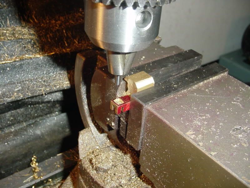
Those 1/16" end mills will get very easy to use after a little bit of practice. The first few times I used one It was a scary experience. I saw one flexing, and that was enough to teach me to slow down, and easy does it. I have a few 1/32 end mills that I hope I never have to use.

I draw and re-draw parts that I make with no experience, or even a slight clue of basic drafting techniques. Often times I cant understand my own drawings, strange but true. But somehow I manage to interpret the gibberish and get the parts made.

After I saw the drawings you posted with all the machine moves all plotted out and easy to understand, I must say that I'm very impressed. With drawing like that I could really crank out some quick builds!

Edit; I think its worth mentioning that the outer diameter of stock round bar is not "really" round. I believe its "drawn" through sizing dies that are less than perfect and don't need to be. Bar stock needs to be trued up by machining its outer diameter if "round" is required by its application, such as a miniature piston. The outer diameter of precision ground rod is more suited for applications requiring a good fit.

Keep up the good work. :)

-MB
 
Brian, those drawings are magnificent. Even -I- can follow them. Bravo!

:bow: :bow: :bow:
 
Slowly we struggle along----Progress is slow when I have "real work" to occupy my time. Thanks for the nice compiments on the drawings. I like design and detail drawings.---I have often said that its nice to have made a lifetime career out of something I enjoy so much.
VALVEASSEMBLED001.jpg

VALVEASSEMBLED002.jpg

 
Looking great Brian.

Is that a through hole on the end of the steam chest? On the dome looking end?
 
No, zee, thats just an indent where I had my live center for the turning operation on the steam chest. In retrospect, if I were to make that part again I would purposely leave that bit longer when I cut out the piece and then grind it smooth after the fact.---Brian
 
I'm very pleased to announce that IT WORKS!!!! I am building this engine to get a better understanding of how this type of valve operates, and to figure out some of the design parameters. I assembled the end caps to the cylinders this morning, and put that big chunk of brass on the end of the piston rod as a "Handle" that I could grab and work the piston back and forth (with lots of oil in the cylinder) untill it "freed up" with very little bind. Then I hooked an airline onto the inlet to the steam chest, and operated the valve by pulling the valve rod in and out by hand (It only moves about 1/8" from one position to the other). And HURRAY!!!! When I operate the valve lever, the piston and rod go back and forth quite smartly---Just like its supposed to. I'm Stoked. Now of course I have to build the rest of the engine.----Brian
TESTINGVALVEACTION001.jpg

TESTINGVALVEACTION002.jpg
 
This evening I got in a little shop time and started to rough out the base, which I made from a piece of aluminum angle. ---It will be a base and also incorporate one of the bearing stands. I have to walk it out to my big stationary belt sander to finish radiusing the top of the bearing stand. I didn't take enough passes on the inside face of the angle while I had it set up in the mill (You can see the unmilled area), so I will have to set it back up in the mill to ensure flatness over the entire area.
anglebase001.jpg
 

Latest posts

Back
Top