Elmers #33---Kind of---

Home Model Engine Machinist Forum

Help Support Home Model Engine Machinist Forum:

This site may earn a commission from merchant affiliate links, including eBay, Amazon, and others.

Brian Rupnow

Design Engineer
Project of the Month Winner
Joined
May 23, 2008
Messages
14,980
Reaction score
8,273
Location
Barrie, Ontario, Canada
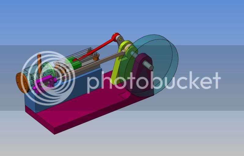
I have decided to build Elmers #33 mill engine--Kind of. I modelled it as per Elmers drawings yesterday, and although his version is very pretty, there are many things that can be simplified without compromising the way the engine works. My smallest fastener that I "stock" is #5-40 shcs., so the engine has been modified to accomodate them. I am working with a box full of scrap aluminum "shorts" from one of my fabricators, so the plans have been modified to suit the peices I have. My smallest end mill is 1/8" diameter, so again, the plans will be tweaked to work with that. Since I have to create detail drawings to work with, I will post them here as usual in case any of you chaps care to build it too. I hope you follow my build, and I hope we have fun.---brian
ASSEMBLY-33.jpg

ASSEMBLY-33-Brian.jpg


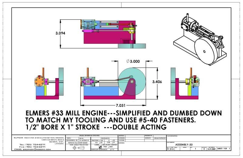
View attachment ASSEMBLY-33.PDF
 
Nothing dumb looking about it. Did you remove the packing nuts? I left them out on my build in favor of just close fits. Cylinder looks like it should be an easier set up also. Is the tube on top intake or exhaust?
 
brain this will be a journey of fun in epic proportions, so please led the way :bow:

chuck
 
black85vette said:
Nothing dumb looking about it. Did you remove the packing nuts? I left them out on my build in favor of just close fits. Cylinder looks like it should be an easier set up also. Is the tube on top intake or exhaust?

Yes, I removed the packing nuts. The tube up top is the air inlet.
 
There's a cylinder in there somewhere!!! I started with a piece of 1 1/2" plate, cut it to 1 1/2" square, set it up in the mill to add a center hole to each end, and drilled one corner for a 3/16" rod which is my drive key when turning between centers. I left one end of it square to act as a reference surface for milling the flat sides on the cylinder. I'm not certain that this is the correct way, but its one of them "Figure it out as I go along" things.
cylinder-1001.jpg

cylinder-1002.jpg
 
Brian Rupnow said:
Yes, I removed the packing nuts. The tube up top is the air inlet.

I could not tell for sure. The inlet side needs to be outboard of the valve assembly. Either on the body itself or the outside plate. It has to keep pressure on the sliding piece inside. Not seeing the detail I could not make out how you routed the air. Here is a picture of mine showing the inlet on the cover plate.


IMG_1393.jpg
 
Hey Brian another awesome build I will be following along I enjoy your builds and the professional way there done Cliff.
 
Hi Brian
Elmer's #33, one of my favourite engines to date. I built to plan two years ago. I liked it so much I then decided to build another but increased the size by 50%. As you can see from the pic I added additional bolts and fed the air inlet through the valve chest cover similar to black85vette. This might be an option for you to consider.
http://i256.photobucket.com/albums/hh200/cormorant2/DSC02173.jpg
(I hope the picture link works - it is a while since I have posted on here !).
I did wonder during the build if the increased size might pose problems with air supply volume but as it turned out the larger engine runs really well on just 5psi and it can also be set to run 'sooooo' slow.

Anyway Brian it's really good to see another take on Elmers Mill Engine and I shall be following your build with great interest.

John S
 
John,

That is truly magnificent. Thanks for the photo. I'm eager to see Brian's engine come together too...
 
Black85vette--you know, it looks like you may be right. I'm a bit confused, as Elmers plans show the valve cover plate as being a blank piece of plate with no air intake on it. I'm not sure if Elmer had it backwards---which seems highly unusual, as he didn't make very many mistakes. On one of the models John shows in his post (the smaller one) he is running a blank plate like Elmer used.
 
Brian Rupnow said:
Black85vette--you know, it looks like you may be right. I'm a bit confused, as Elmers plans show the valve cover plate as being a blank piece of plate with no air intake on it. I'm not sure if Elmer had it backwards---which seems highly unusual, as he didn't make very many mistakes. On one of the models John shows in his post (the smaller one) he is running a blank plate like Elmer used.

Yes Elmer had the intake on the body not the plate, and on John's smaller engine you can see the air supply is going into the top of the valve body which still puts it outboard of the valve. It was a practical matter for me. The valve body was aluminum and the plate was brass. I opted to go the easy route and just used solder on the brass. On the inside plate with the 9 holes the left 3 and right 3 each go to their end of the cylinder the center 3 go into the exhaust which dumps out below the valve body. It is just a hole on mine. On John's larger engine you can see where his exhaust is connected at the bottom.
 
Black85vette--Now I get it--Thanks--I missed the air intake hole #5-40 on the side of Elmers steam chest. That makes the vertical stack on my engine the exhaust. Thanks for clearing that up.
 
Yes Brian, that's the usual position for the exhaust outlet. Also you will need a knuckle joint on between the valve spindle and eccentric rod.
 
tel said:
Yes Brian, that's the usual position for the exhaust outlet. Also you will need a knuckle joint on between the valve spindle and eccentric rod.

Tel--I'm using the same joint that Elmer showed in his design. Am I missing something?
 
Brian,

Having those Solidworks images in addition to the drawn plans makes visualization so much easier. Great job! When you finish the build and consolidate the plan upload, I trust you will include the SW images. I would like to try this build too, although I already have a lot of build backlog. Seeing the finished builds is great.

FWIW, I thin having the flywheel inside the bearing post looks better than outside, but I'm guessing one could do it either way.
 
Back
Top