Elmers #33---Kind of---

Home Model Engine Machinist Forum

Help Support Home Model Engine Machinist Forum:

This site may earn a commission from merchant affiliate links, including eBay, Amazon, and others.
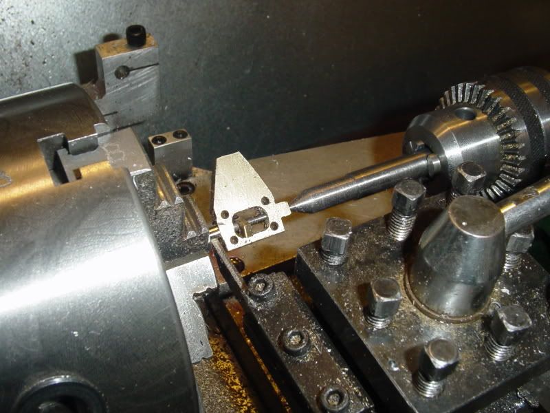
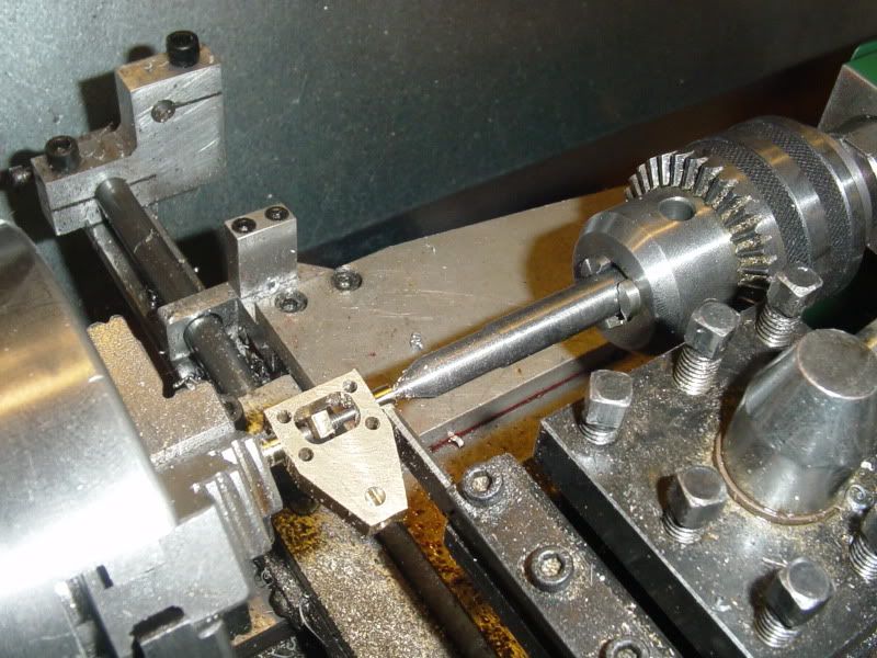
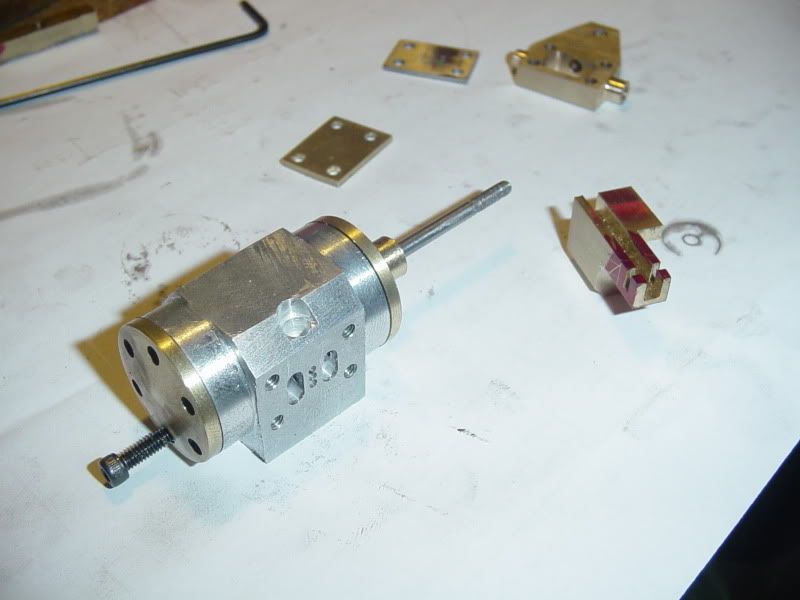
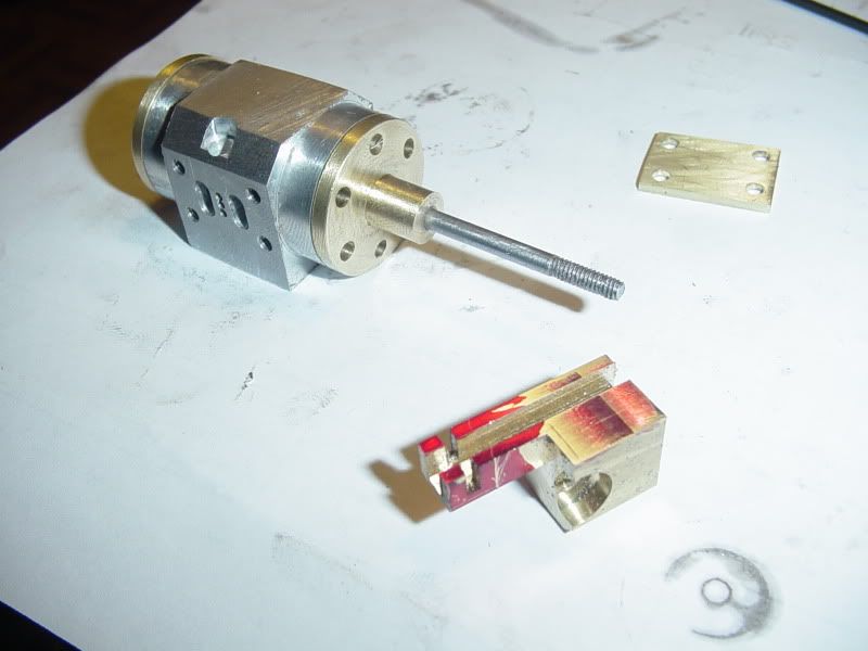
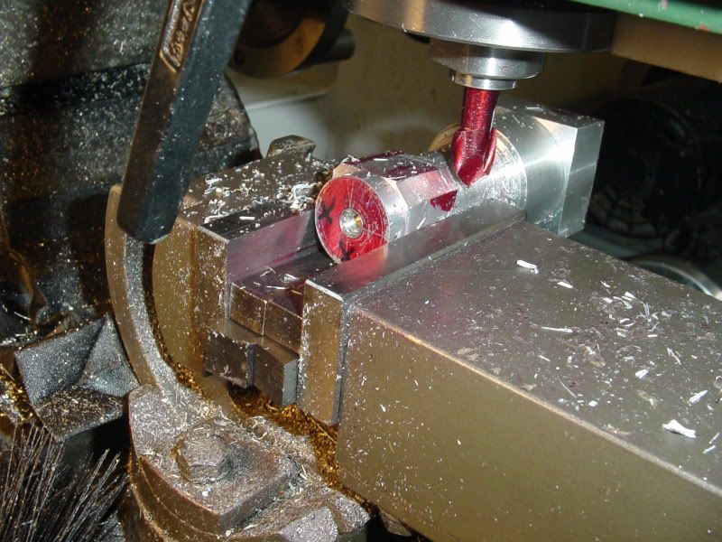
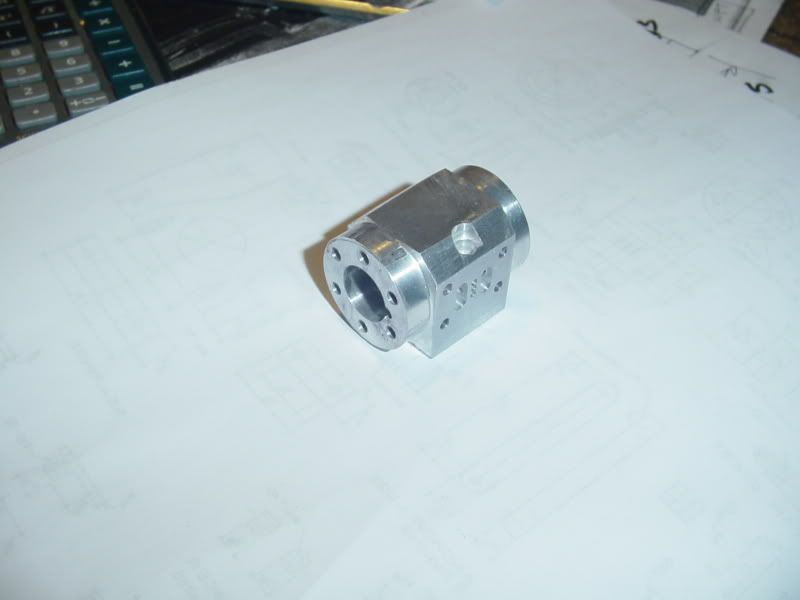
This is my new chamfering tool in use. I coloured it red with layout dye so I wouldn't keep picking it up and trying to use it as a normal end mill. It works great--in fact, it works so good that I chamfered the one corner where the boss for the exhaust pipe sticks up completely away, then realized that "Hey!!! --That was only supposed to be a partial chamfer!!!"--Oh well, I'm the designer--I'll just change the plan to match the part.
CYLINDER-2005.jpg
 
Here we are, set up to drill the holes that run on an angle from the ports to the end of the cylinder bore. I love my 'Tilt a Whirl" vice!! It really works well for this type of thing.
CYLINDER-2007.jpg
 
Brian Rupnow said:
Tel--I'm using the same joint that Elmer showed in his design. Am I missing something?

S'orrite Brian, just my eyes perhaps, but on the smaller drawing it looked to me like a solid connection - I can see it clearer on the bigger cutaway
 
And here we are, almost finished. I have to tap 18 holes and then this part should be good to go. I didn't drill and ream the bore untill after I had the small holes drilled that are shown in the previous post, because they start so close to the bore that I thought it would be difficult to start the drill if the 1/2" bore was there. The hole you see in the previous post was drilled and reamed to 3/8" diameter, then after the small holes were drilled I put the cylinder back in the lathe and finished opening the bore out to 1/2" diameter.
CYLINDER-3001.jpg
 
Looking good. I like the shape of the cylinder. I think this was the part that got me to drill and tap as much as possible early because I did all the lathe and mill work only to break off a tap in it. :Doh:
 
My tapping went succesfully, just finished it. A few of my tapped holes broke through into the cylinder bore, but I'm not too concerned about it. The bolts will plug the holes, and since this cylinder ends up having a 1/4" thick wall, I don't think its boing to "blow out" . The piston will be made from brass, and should be long enough (1/4") to skate over any of the holes that broke through.
 
Brian Rupnow said:
A few of my tapped holes broke through into the cylinder bore, but I'm not too concerned about it. The bolts will plug the holes,

Been there, done that.
 
Hi Brian

You might consider using studs rather than bolts which would give you several benefits. Most importantly the studs could be 'loctited' into position which would seal up the holes nicely.

In addition as you are making your cylinder block from aluminium the use of the stud approach would avoid the danger of stripped threads in the relatively soft material. As you know during the build process you may require to fit and remove cylinder and steam chest covers several times which could weaken thread holding power in aluminium.

In 'real time' these covers were nearly always fitted with studs and nuts, rather than bolts, and as a result provides a more authentic appearance. Oh and BTW studding and nuts is less expensive than nuts and bolts !

Incidentally I have started to use 0.25mm PTFE sheet as gasket material which is available from

http://www.directplasticsonline.co.uk/PTFESheet/?&gclid=CJLC67HZzZ4CFY8A4wodSk2osA

This provides an excellent air (steam) tight seal without having to overtighten fasteners.

John S
 
John--Thanks for the information. I will probably use the socket head capscrews, because I have them. I agree, I will have to use some kind of gasket material. For small engines like this I have often used oiled paper, since the compression forces are very low, in the -30 psi range. I may use a piece of 1/16" clear lexan for the valve cover plate, so that the action of the valve is visible. Thank you for taking an interest in my post.---Brian
 
Brian; another thought regarding the piston. As I recall Elmer had the connecting rod threaded into the piston. I tried that but ended up with a standard wrist pin configuration. Could have been my lack of equipment or experience but getting the alignment perfect with a rigid connecting rod didn't work for me.
 
Another part done--No rocket science here, but a couple of very scary set-ups. There is a round boss on both ends of the steam chest. I drilled and reamed the 1/8" and the 3/32" holes in the mill while everything was still in the "flat" Then I turned the end of a 1/8" steel rod down to 3/32" and threaded the first 9/32" of full diameter on it with a #5-40 thread. Made up a nut from a piece of brass and assembled it all, then chucked the rod in my 3 jaw on the lathe, and stuck in a 3/16" hex hut for a spacer. I put a "dead center" in the lathe chuck and gave it a bit of a tap to anchor the outboard end of the part, and used my cut-off tool as a turning tool to get in and turn the bosses to finished diameter. Took very light cuts and held my breath the whole time---And just noticed as I posted this that I drilled the hole for the air inlet pipe on the wrong side!!!!
STEAMCHEST005.jpg

STEAMCHEST002.jpg

STEAMCHEST004.jpg
 
Brian Rupnow said:
And just noticed as I posted this that I drilled the hole for the air inlet pipe on the wrong side!!!!

Nah. You were just planning on making a mirror image twin. You just didn't know it, yet.
 
Don't feel bad Brian. I was about to make the very same mistake when the UPS guy rang the doorbell and disrupted me. When I got back to the shop. I lost my place in the process, and started all over again to catch the mistake! One cylinder head was reversed in the vise and ready to be drilled for the intake tube! :mad:

That makes the third near miss today!

I think I'll just post what I have and call it a day.

-MB
 
This is why they invented Sharpies, guys.

Whenever I have a "handed" part, I mark up the sized blank with the hole locations. (I often don't lay out, depending instead on coordinate milling/drilling.) It's saved me many, many times. It's just too easy to get things turned around while experimenting with clamping arrangements and setups.

Part of good machining practice is being aware of one's personal tendencies to make errors and putting in place procedures to prevent such errors, then following those procedures religiously. Discipline is a virtue.
 
Whadaya mean "Tendency to make errors!!!'---Jeez!!!! I've been designing parts since 1965--I've only been making them since 2007. ;D ;D--At any rate, I'm not to concerned. I'll just make an inlet tube with a blind hole in it and put the "wrong side" hole all the way through.---Although that does bring to light an old "design rule" that I ignored, to my detriment. -Back just after the dinosaurs died out, when I was in my apprenticeship, I was taught to always show part details in the same orientation as they appeared in the General Arrangement drawing. I don't at this stage have a General Arrangement drawing, but my assembly model that I refer to is shown opposite to the orientation of the part in the detail drawing.--And that, boys and girls, is what screwed me up!! The people that made up all those "Rules" did so with good reason.
 
Well, I got this far today, then I got a call to go and quote on a "Real" job---Designing a hydraulic powered boat lift for cabin cruisers---BIG cabin cruisers!!! It looks like I got the contract, so now my engine progress will take a back seat for a while---while I make some money. I've had my own design/engineering company for 10 years now, and I think I've made the same money this year as I did in 1973 or thereabouts. There's only about 2 weeks left to round up my year, so I don't think I'll be competing with Donald Trump this year. :'( :'(
parts-1001.jpg
 
I spent this morning climbing around some existing boat lifts and taking measurements--Hell no, I'm not copying someone elses design--I'm gathering reference material!!! ;D ;D This afternoon I started to make the valve and got as far as what you see in the picture----Then figured it out that I DO NEED a 1/16" end mill after all, and couldn't go any farther. So---I made both cylinder end caps, a piston, and a connecting rod. Now I'm off to my cup of SleepyTime herbal tea (Yucchhh) and then to bed.
ASSYCYLANDENDCAPS001.jpg

ASSYCYLANDENDCAPS002.jpg
 
Looking good Brian.
And I'm glad the 'real job' isn't getting in your way. ;D
 
Brain, looking good, you make it seem so simple, easy and fast to do, guess that what a teacher does, I want to make a lot of the things you are making but will have to live to be several hundred years old are get a lot better at machinging, thanks again for sharing your knowledge and skills, Lathe Nut
 

Latest posts

Back
Top