Dave's twin

Home Model Engine Machinist Forum

Help Support Home Model Engine Machinist Forum:

This site may earn a commission from merchant affiliate links, including eBay, Amazon, and others.
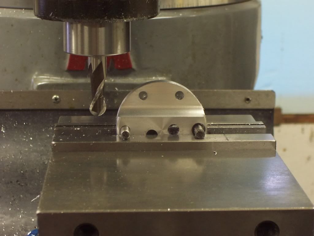
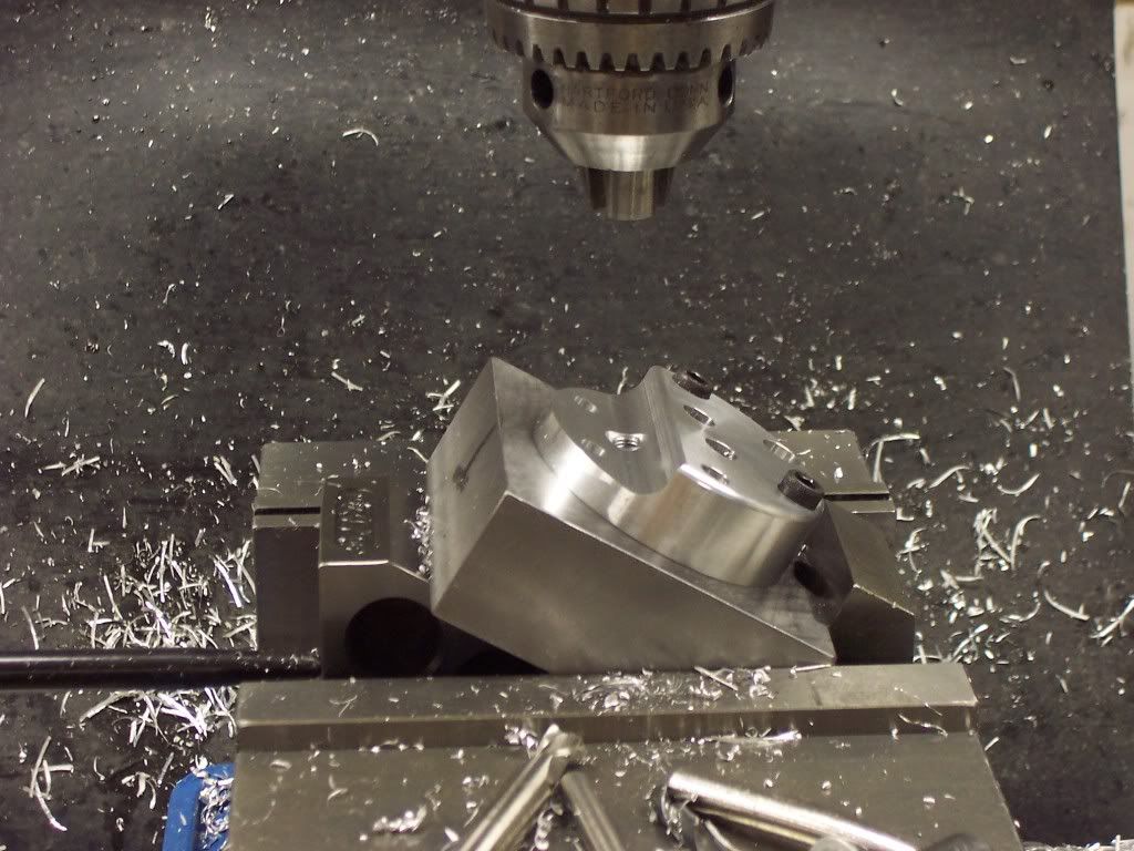
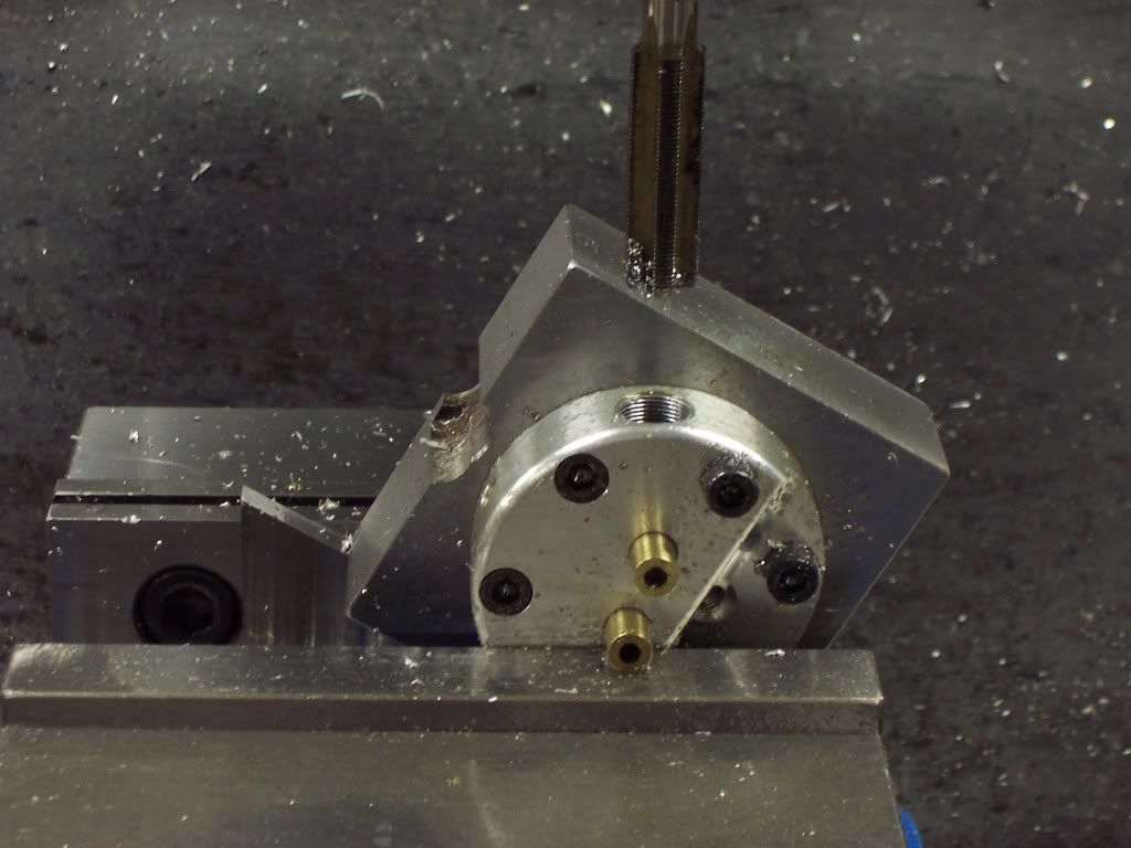
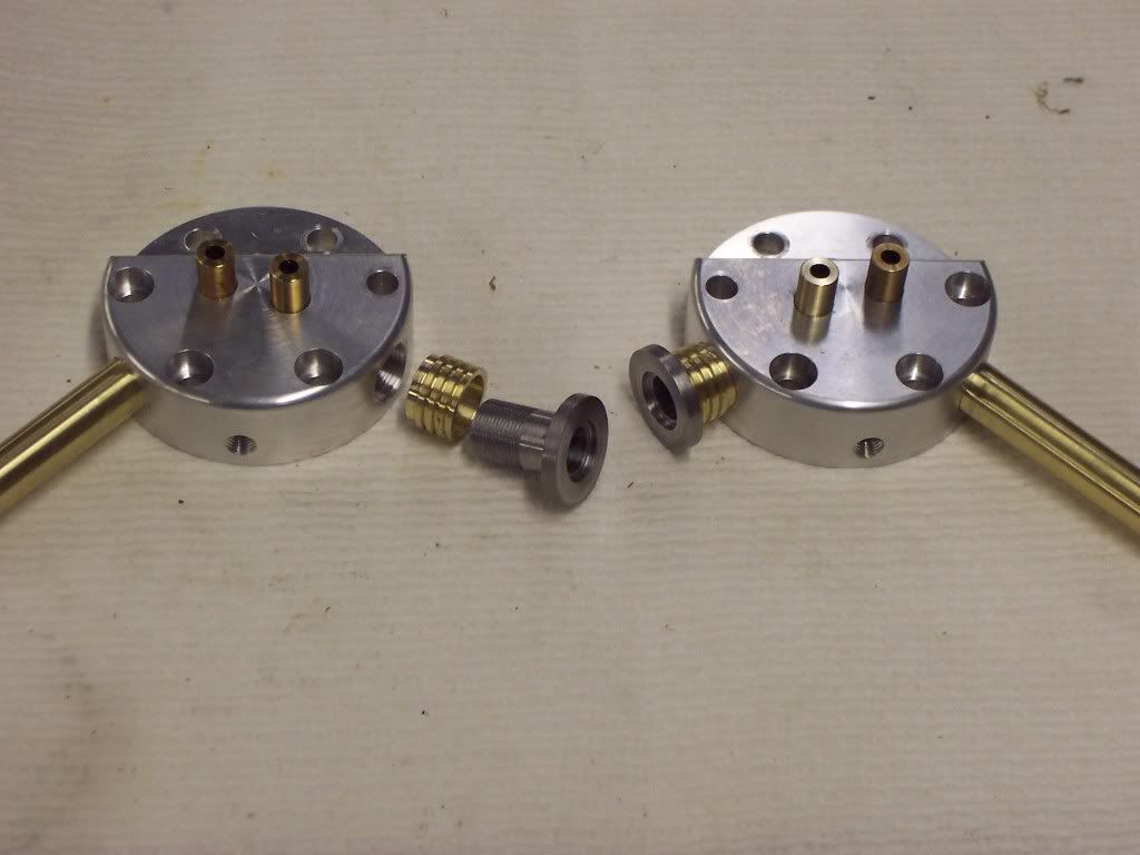
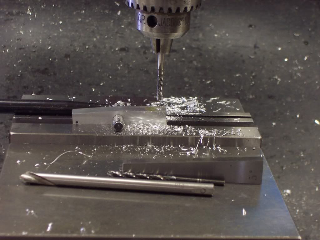
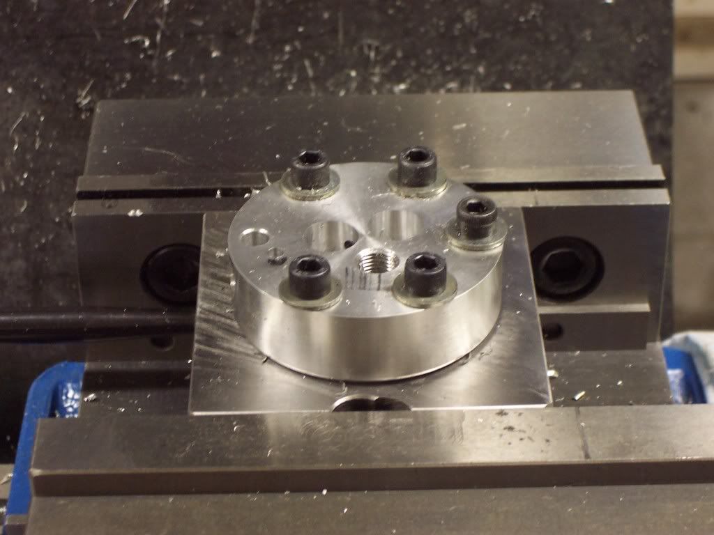
Heres a pic of the head mounted to the fixture upside down so the holes for the valve cages can be seen. I used a small woodruff key cutter to extend the slot for the coolant to surround the exhaust valve cage. Heres where I made my first big OOPS. When withdrawing the keycutter from the hole on the last part I drug it across the surface of the hole leaving a large void where coolant will leak. I have a replacement started and will finish soon.

102_1197.jpg


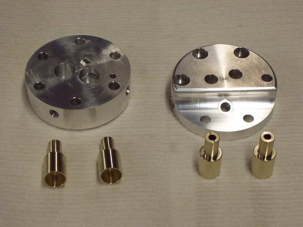
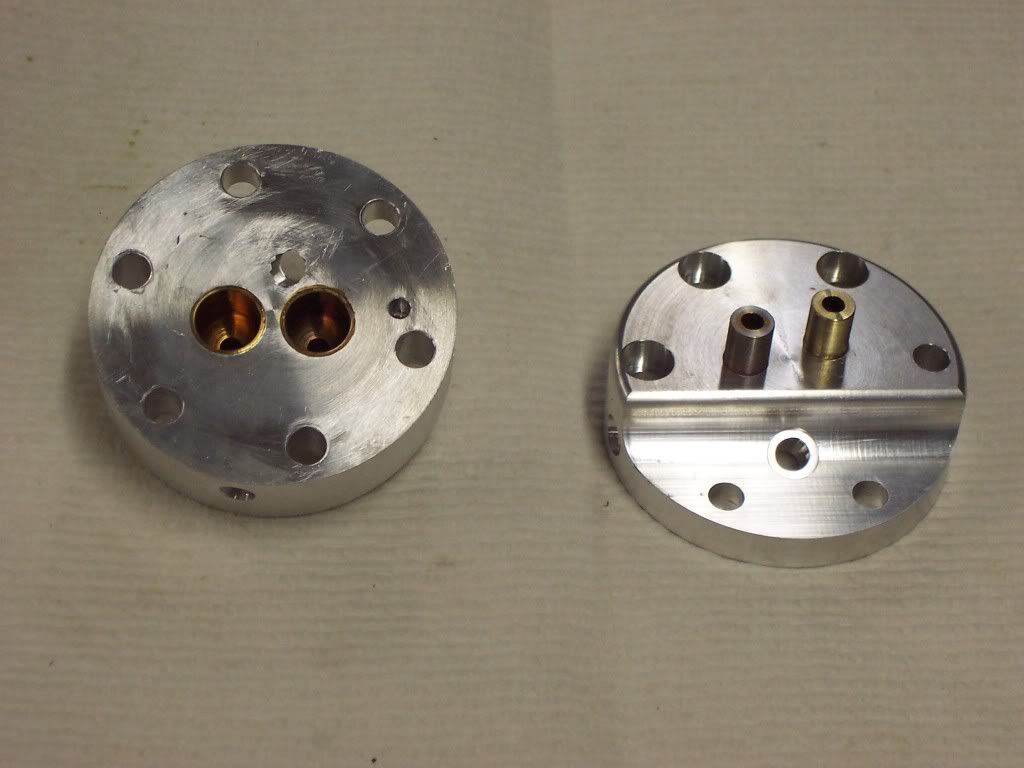
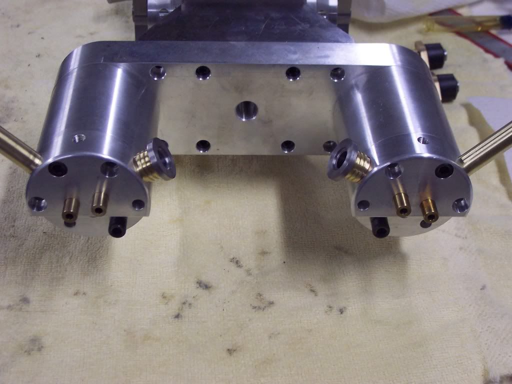
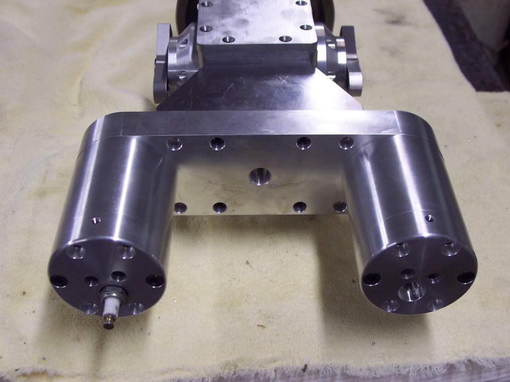
Heres a pic of the heads attached to the cylinders. I am going to open up the coolant lines some before I go any further. I was originally going to use 3/16 fittings but I think they will be too restrictive so I will open everything up to 1/4".

102_1199.jpg
 
Dave, I've got to say, That is one very imaginative engine. You are doing great work, I'm impressed with both the idea and the quality of your machining.---Brian
 
Thanks Brian. For an update, I have finished my customer work and in the proccess I have managed to destroy a bearing in the head of my mill. My modeling work doesn't tax my machine much because of the small size of most of the parts but the last work I did had alot of extra stock so I kinda got carried away with some very large cuts to save some time. Well during one of these cuts my mill started to squeal in pain. I finished the job as the mill would still run and I was on the last part anyways. My son and I tore into it the other day and we found one bad bearing. Its the bearing that takes the axial load on the movable pulley on the variable speed. I have a new bearing on order at a cost of $106 and it should be here in the next few days. Hopefully the reassembly will go well and I will be back to the twin soon.
I have decided to redesign the heads a little. I need to remake one anyways so I will just start over. After making the first ones I didn't like how close the sparkplug was to the rocker arm. I will also use the 1/4-32 plug instead of the larger NGK. I didn't have much work in the first set of heads so not much is lost. I'm sure sitting at the computer and drawing them first would have helped but that would be too easy. I like to do things the hard way. I took one of the heads I will scrap and modified it for an example to see how it looks and I am happy with the results.
My mill should be back together this week so I can continue with the twin. Dave
 
It took a little longer than I expected to get my mill back together but it is finished and running better than ever. I went ahead and made a new pair of heads. In this pic I am milling away the area for the spark plug. Using a ball endmill will give me a radius in the corner.

102_1205.jpg


Before removing from the fixture I used a 3/32" corner cutter to round off the edge. I remounted the fixture in the vise so I could drill and tap the hole for the spark plug. A shallow counter-bore was milled in for the gasket to seat to.

102_1206.jpg
 
The valve cages came next. They were made from aluminum bronze. A tough material but good for seats and guides. A piece of stock was chucked in the lathe and the od was turned to clean up. The end was faced and a .149" dia hole was drilled to a depth of 1.125". A 7/16" dia ball endmill was plunged into the part to a depth of .525" to form the bowl area. The guide hole was now reamed to size and the od turned to a finish dia of .501" to give me a press fit of .001" in the head. Before parting off my 45 degree seat cutter was used to cut a seat in the cage. After parting them off they were remounted in the collet in the lathe and faced to a length of 1.125". A .311" dia was turned on the end to fit in the .3125" dia hole in the head. The heads were then put on my hotplate and heated until the cages slipped into holes with no effort. A light coat of loctite was applied to the od of the cage. I made a pusher from CRS that slipped into the guide hole and pushed on the bowl radius for easier installation. A pic of the cages before assembly.

102_1208.jpg
 
Once the cages were installed and the heads allowed to cool they needed to be set up so the port holes could be drilled. The heads were once again bolted to the fixture and mounted in the vise on the proper angle. The intake ports were drilled to intersect the cage with a 3/8" dia ball endmill. I used a 1/2-32 tap to make threads for mounting an extention onto the head. The exhaust ports were done the same way but were 5/16" dia and tapped 7/16-32 for an exhaust pipe. All 4 ports were done the same way.

102_1210.jpg
 
The port extentions were next. They were made from CRS. I would have prefered 303 SS but I didn't have any large enough to do the job. They were turned to dia and a .500" dia was turned so it could be threaded to match the port hole. They were single pointed in the lathe and then the .375" dia hole was drilled and they were parted off. They were turned around and installed in the collet and faced to length. I bored a pocket in the face for an O-ring for port seal. A brass spacer was turned to size so it could be sandwiched between the extention and the head. This pic shows one head with the extention installed and one yet to be installed.

102_1211.jpg
 
Heres a pic of the heads installed on the engine finished to this point. The round heads of the extentions will be contoured when the mating pieces are made. I will setup the heads next and drill and tap for the intake attaching holes. I don't like the exhaust pipes and once this thing runs I will probably change them.

102_1212.jpg
 
It's looking good so far, I like the little brass spacers on the intake.

Jim
 
Thanks guys, it was 66 degrees F today so no time in the shop. The nicest day in quite some time for us so I spent the day outside. Rain and colder tomorrow is the forcast so I hope to be in the shop all day. Dave
 
Dave G said:
The valve cages came next.... and the od turned to a finish dia of .501" to give me a press fit of .001" in the head.

So if I understand from your posted subsequent step, you then heat up the head, insert the room temp (or chilled?) valve cage, they cool together & that interference fit is what maintains the valve cage in permanent position thereafter in operating conditions, right? No high temp locktite used?

If so, how hot does the head have to be for this? (Im wondering about the cage taking on heat transfer quickly & therefore having to work quick getting it landed in position & not stuck short?)
 
Dave,
I don't know how I missed seeing this build til now. Totally awsome.
Alan
 
The interference was .001" and the cages were .500" dia. I left the cages room temp and applied loctite on the OD. The heads were placed on a electric hotplate that I bought for the shop. I didn't monitor the temp of the heads but they got hot enough to discolor the cages after installation. The cages did slip right in and went all the way to the bottom of the pocket. I turned up a pusher that piloted in the guide hole and pushed on the bowl radius. I made sure I had a good surface finish on the walls of the pockets in the head and everything was deburred carefully to make sure there were no obstructions or voids where coolant could leak. I don't expect any leakage of coolant. I used loctite more as a lube and a void filler than a retaining compound. Normally you should leave a void for the loctite but I felt an interference fit would be better. Time will tell, I guess I'm just old school and don't trust loctite as a retaining compound in this application. The cage was inserted and pushed all the way to the bottom of the pocket with one motion, you only get one chance and if you stop before reaching bottom it will stop there with little luck of moving further. I figured if something went wrong I could always reduce the dia of the cages and loctite them in place as a second option.
Where I used to work we had some jobs where the press fit between 2 pieces was quite excessive, the smaller piece was put into a freezer we had that was used to stabilize parts after heat treat and was -100degrees F and the outer piece was heated to just below the temp that would cause permanent transformation of the structure. Both parts were usually hardened to 56 RC plus and were made from toolsteel. Putting them together usually wasn't too bad of a job but when they came back for rework no one wanted that job. Taking them back apart made for some tense moments.
Since you asked, I will try to check the temp of my hotplate soon and post the results. I know it will turn mild steel blue. Dave
 
My hotplate checked at 430 degrees F. I went ahead and made the valves next. A length of 303 SS was placed in the jaws of the lathe with enough stickout to finish the job. The OD was turned to .158 for a length of .5". My finished dia should be .1555" and will be finished when the last cut is made. After the first series of cuts to .5" I next turned the next .5" to .159" dia. Once this was finished I turned the last little bit to .159" dia. Heres a pic of the first cut finished and the second cut partially finished.

102_1213.jpg


Heres a pic of the next cut which will leave the OD at .159" for the full length of the valve stem.

102_1214.jpg
 
Heres a pic of the tool I use to cut my seat surface of the valve. Its a HS toolbit that was ground to a 45 degree angle and relieved by hand.

102_1216.jpg
 
A pic of the 4 valves after parting off. The valves were inserted in the collet of the lathe from the backside and the keeper grooves were cut with a grooving tool.

102_1219.jpg


Once the valves are completed all there is left to do is to hone the seat surface. I do this by setting my toolpost of the lathe at 45 degrees, easily done by clamping my square head to the toolpost and indicating true. The valve stem is placed in the collet and the seat surface is inked up and a fine Arkansas stone is placed up against the toolpost as a guide and the carriage of the lathe is moved until the stone removes the ink from the seat. After stoning smooth the surface is further honed by wrapping a piece of 400 then 600 grit paper around a piece of keystock and polishing the seat surface using the toolpost as a guide also.

102_1218.jpg


I have found that this way works well for me and usually my valves will seat without any lapping.
 
The rocker arms come next. After squaring up the stock to size the stock was placed in the mill vise and the .250" dia hole was reamed to size. This for a bushing that the pivot pin will ride on. The other hole is reamed to .0625" dia for the roller pivot pin.

102_1220.jpg


Next I needed to mill a 5 degree angle on the bottom of the rocker so they were setup on a 5 degree angle using an angle block.
The pivot pin was indicated to find the location for the adjuster hole which is also on a 5 degree angle.

102_1221.jpg


The center of the rocker was found by sweeping both edges with an indicator.

102_1222.jpg
 
Heres a pic of the bottom surface milled to size and the hole for the adjuster being spot drilled.

102_1223.jpg


A pic of the adjuster hole being tapped.

102_1224.jpg
 

Latest posts

Back
Top