Dave's twin

Home Model Engine Machinist Forum

Help Support Home Model Engine Machinist Forum:

This site may earn a commission from merchant affiliate links, including eBay, Amazon, and others.

Dave G

Well-Known Member
Joined
Jan 15, 2011
Messages
393
Reaction score
1
Well, I have finally found some time to start another engine. This will be my first attempt at posting a build here so please keep this in mind as we go. Any helpful suggestions on my posting will be gratefully accepted.

I like to build my own designs and I have been thinking about this one for a while now. It will be a twin cylinder IC engine of four stroke design. I have wanted to build an engine with all roller bearing construction for a while now and this is what I have come up with. I don't normally do much drawing before I start and this one will be no different. I hope you will be able to follow along and as it takes shape it should become much clearer to understand.

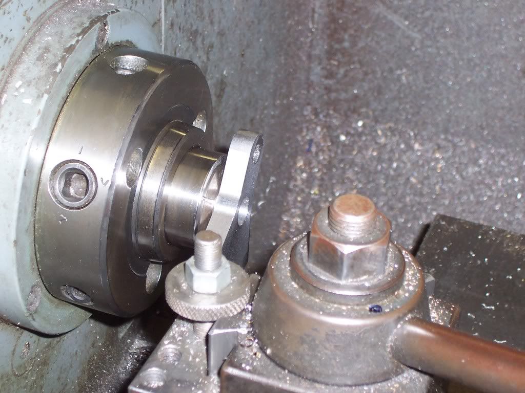
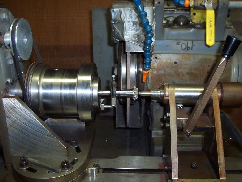
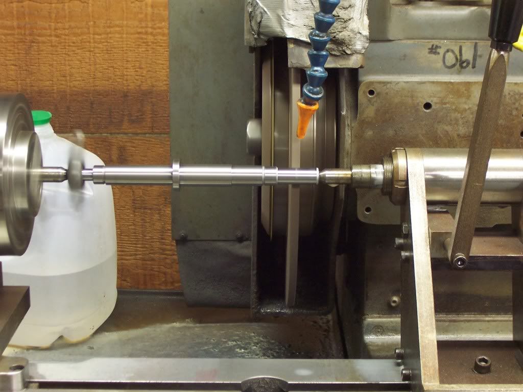
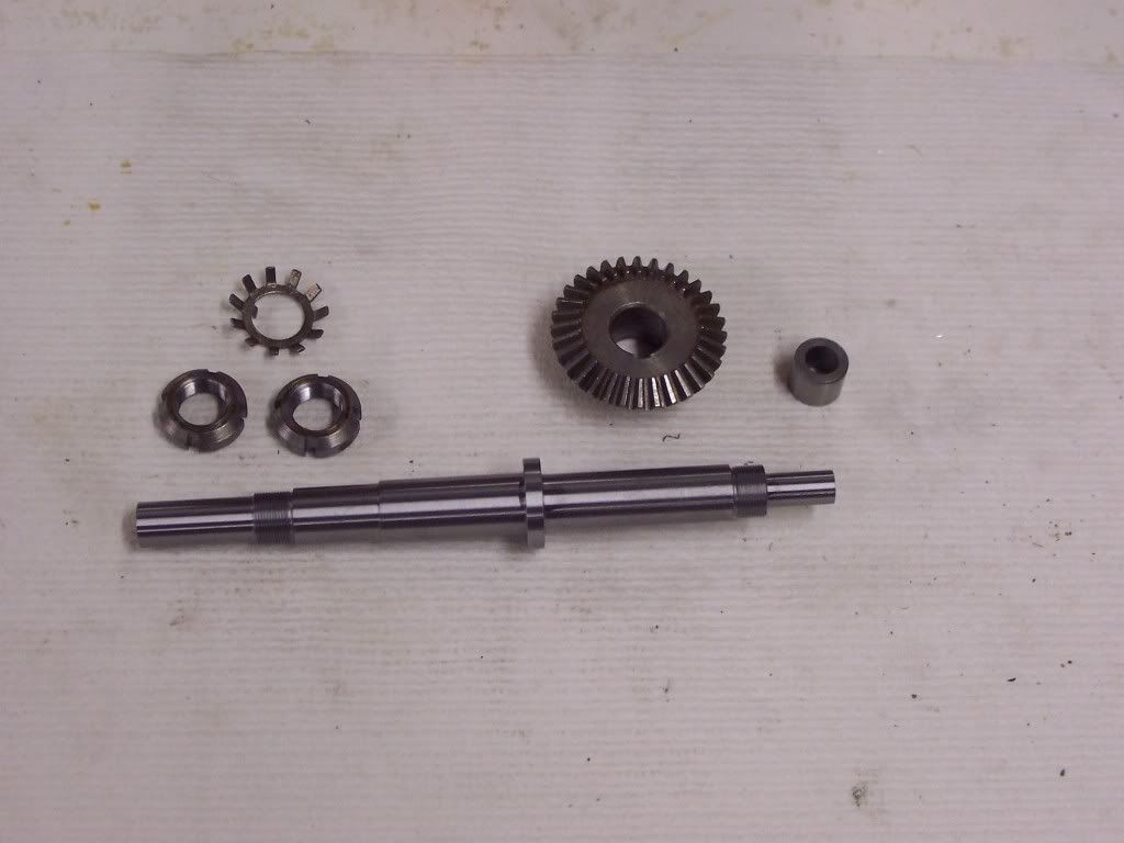
I picked up a couple of 2:1 bevel gear sets at an engine show a while back and tried to figure how I could incorporate them into an engine. What I came up with is the smaller gears which are the pinions are on integral shafts which will have crankdisks attached to the outboard ends. The pinions will act on the larger ring gear which the flywheel will be attached to.
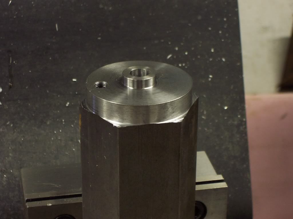
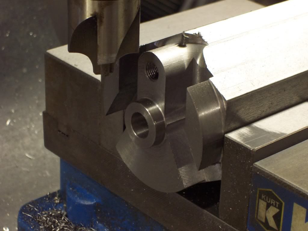
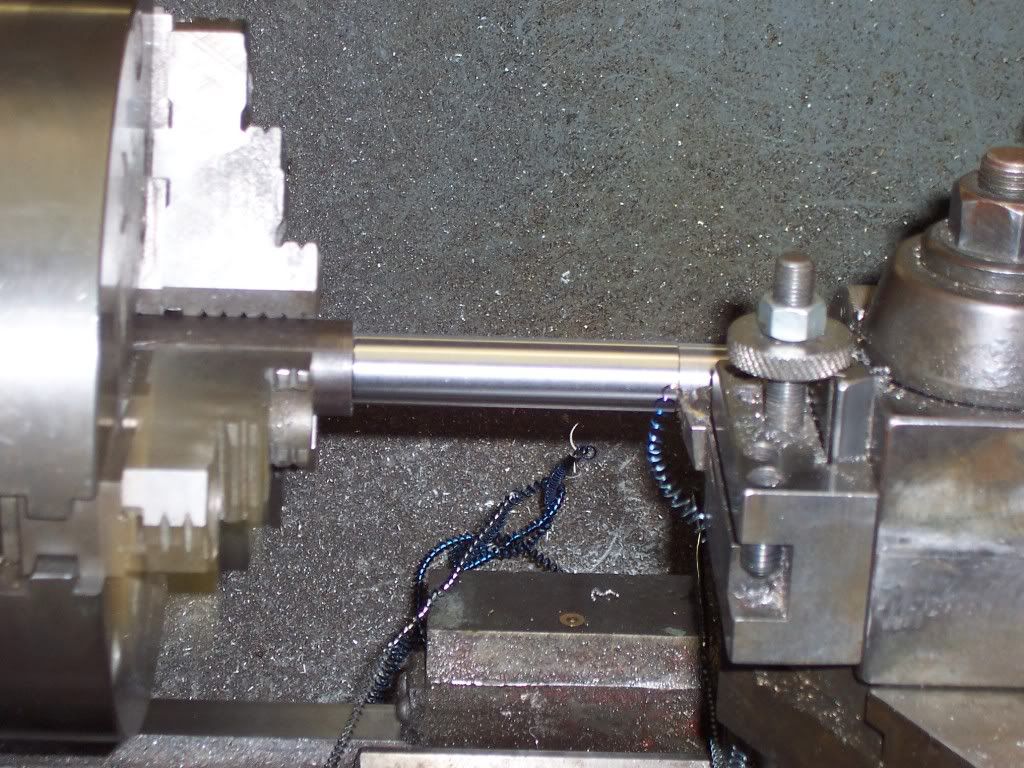
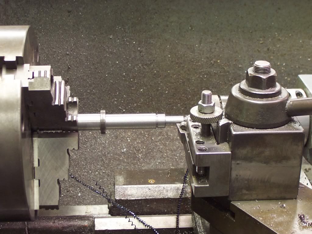
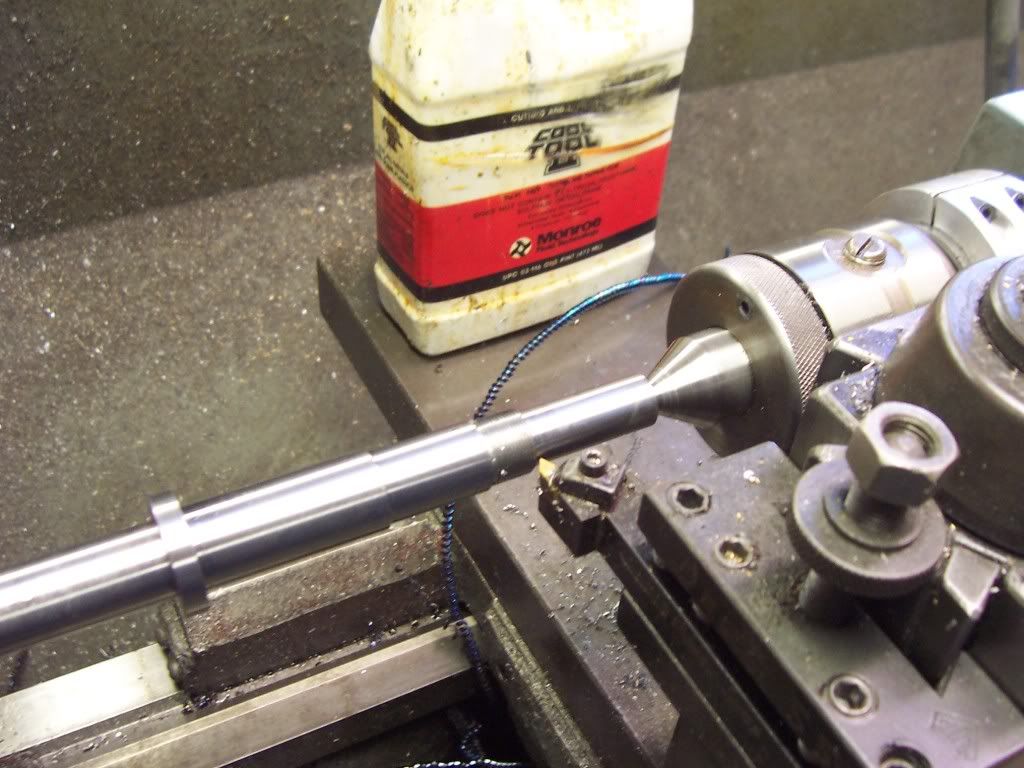
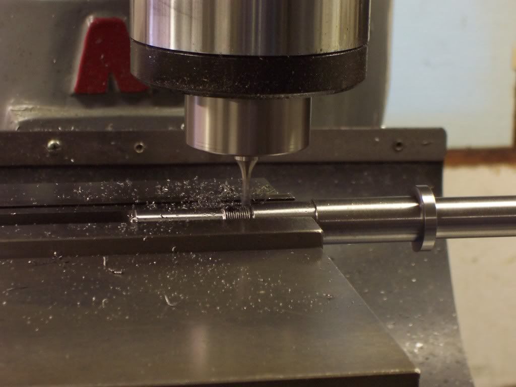
So the flywheel will rotate at half engine speed with the exhaust valve cam attached to the other end of this shaft. One cam lobe will operate both cylinders. This will be a slow speed throttle governed engine so I will use atmospheric intake valves. The first pic I have is of the work I have finished so far( not much ).

102_1053.jpg


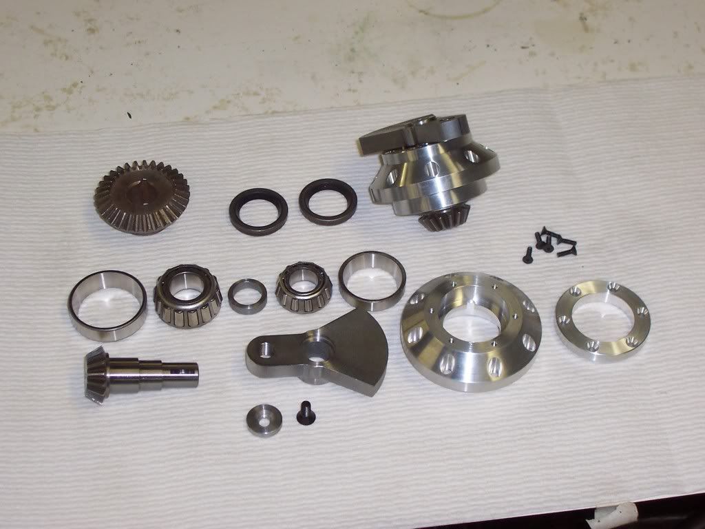
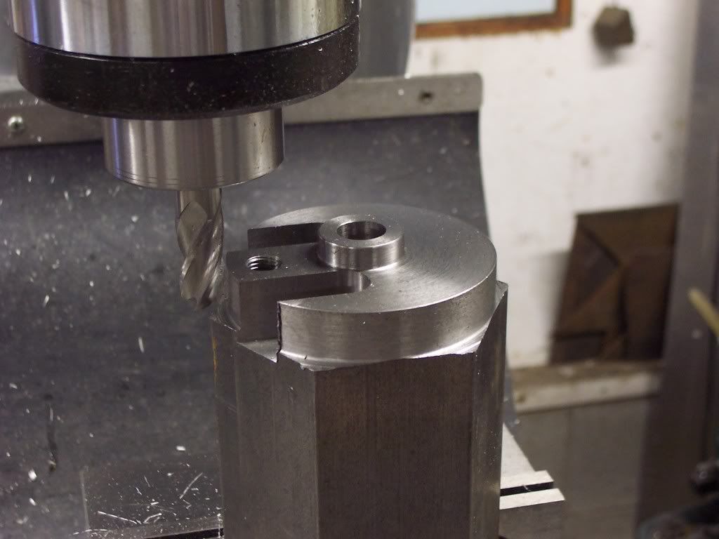
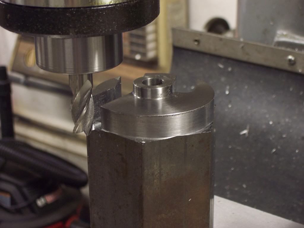
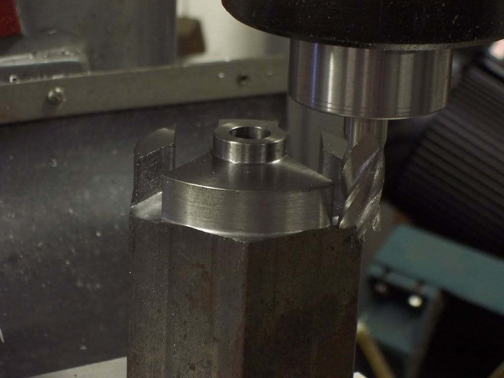
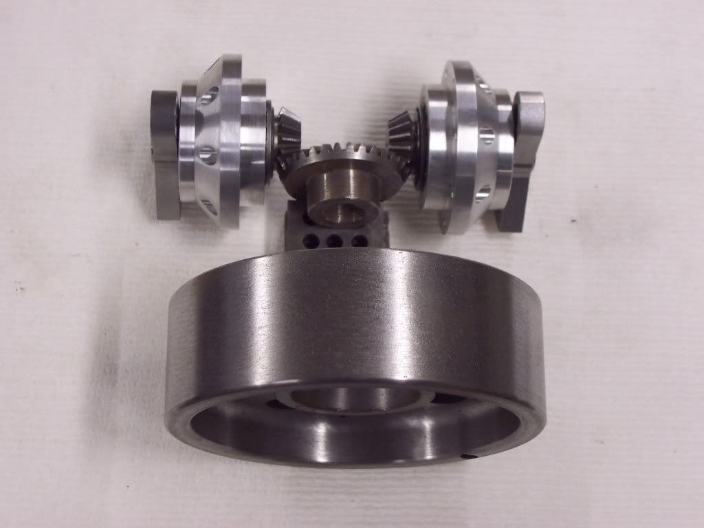
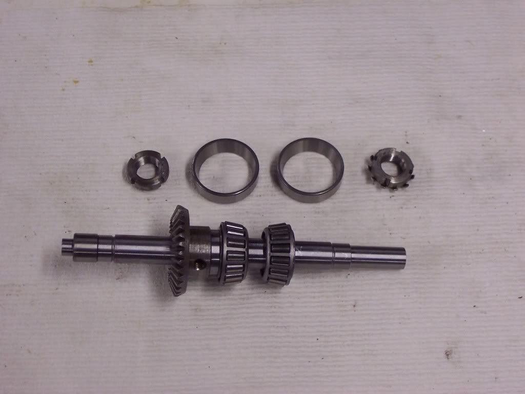
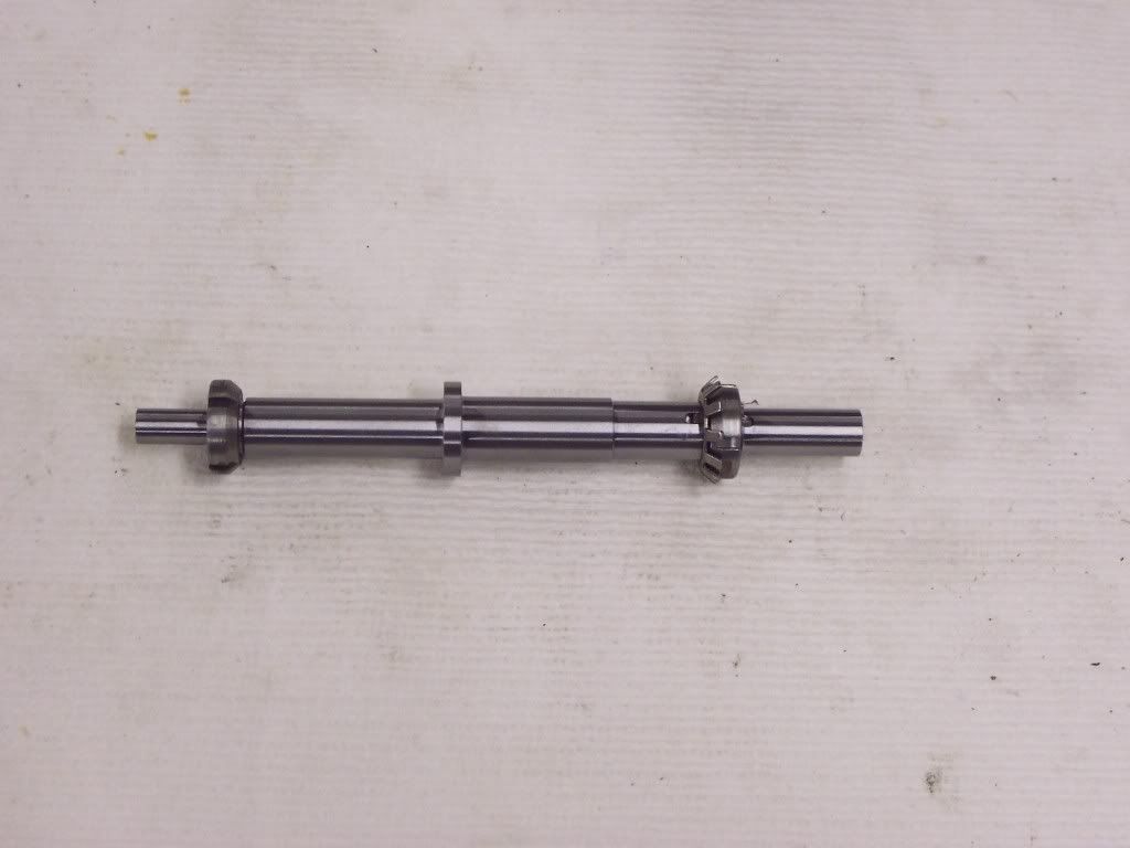
Here I have one pinion assembly put together and the other in pieces. These are constructed like the pinion supports in Ford 9" differentials.


The crankdisks were made from a piece of 2 3/4 hex 12L14 I had laying around. This pic shows the turning done and then setup in the mill vise and the 3/8-24 tapped hole for the rod journal already done.

102_1044.jpg


The pinion shafts were .500 dia when started but I had to install a sleave on the shafts to get the right dias. for the taper roller bearings to fit. While I had to OD grind the sleave to dia I went ahead and ground the crankdisk dia to .497. to true it up with my new dias. The crankdisks were bored on the lathe to .496" dia to be honed to size later. The small dia is for a .875" dia seal to ride on.
 
Here I have used a 1/2" dia endmill to make the cuts for the sides of the crankdisk.

102_1046.jpg


These cuts were made referenced from the center of the part and the depth was greater then needed for a reason I will explain later. The cuts were terminated just short of contacting the seal dia.
 
This pic shows the part rotated in the vise and clamped on the flats of the hex as before. Now a cut was made to form one of the sides of the counterweight.

102_1047.jpg
 
Here I have once again rotated the part in the vise jaws and made the cut for the other side of the counterweight.

102_1048.jpg
 
Now I have repositioned the part in the vise so I can radius the rod journal end of the crankdisk. I did this with a 3/8" corner round cutter.

102_1051.jpg


After completing the radii I took the part to the cutoff saw and severed the part from the stock.
 
Now I need to finish the crankdisk to width. I clamped the disk in the lathe using a 7/8" collet. Taking light cuts I faced the disk so it was cleaned up but not to size. I need to have both faces parallel to each other so after cleaning up the surface I measured the width with mics to check for parallelism. I found the disk to be out of kilter about .002". I marked the thickest point on the face with a marker and then put my dial indicator on the face of the disk and where it was the thickest I lightly tapped the part until my indicator gave me a reading of about .003" runout. Another light cut was made and then checked again with my mics. I did this until I had less than .0005" difference in thickness and then I faced the part to a thickness of .375".

102_1052.jpg


Once both crankdisks were finished to thickness they were deburred and then I honed the bores to .497 plus about .0003 for clearance for the shafts.
 
Hello Dave,

This looks like an interesting and informative build. I'll looking forward to following your notes and photos.

What bore and stroke are you planning?

Regards,

Chuck
 
Hi Dave
Ive been waiting for this build for ages.
Looking great so far :bow: :bow:
Pete
 
Thanks guys, This thing will have a 1.250" bore and a 2" stroke. I have some rings left from my sideshaft engine build which also has a 1.250" bore. I am going to try to duplicate the rod length and stroke combination from my sideshaft to help cut down on the engineering abit. The compression ratio will be 4:1, I have tendency to build too much compression in my engines so this one will be kept low. I use a Sunnen honing machine to finish my cylinders and one ring on the piston and usually get good compression this way.

My biggest concern with this engine is starting it. Because the flywheel runs at half speed and the engine will be started from the flywheel shaft, the mechanical disadvantage of the flywheel turning the crankdisks will make it difficult to turn. I hoping the low compression and maybe a handcrank of large proportion will do the trick, we will see. I may have to borrow one of those starters the top fuel dragster guys use.


Keep tuned and lets hope all goes well, Dave

 
How about commpression release/priming petcocks like the old two cylinder John Deeres with no electric start.

As a kid, I enjoyed watching our neighbor grab the flywheel and crank his 1937 G. Sixty two years later I can still hear all the hissing as the cylinders came up on compression and began to fire. Odd the things we remember for years.

Regards,


Chuck
 
Heres a pic of grinding the OD of the pinion shaft.

102_1025.jpg


I had 2 bearing dias and the crankdisk dia to grind.
 
This may help clear up what I'm trying build.

102_1055.jpg


The flywheel is a weight that came off the slip yoke of a Dodge truck transmission. I chucked it up in the lathe and turned all the surfaces true to clean them up. I finished the pinion support assemblies today. I had to surface grind the thickness of the inner spacer of the second assembly to get the proper preload on the bearings. I also broached the keyways in the crankdisks for the woodruff keys in the pinion shafts. This took some doing as the keyways have to be indexed with the rod pin holes. A keyway broach bushing and an alignment fixture to orient it. It took all day to make the fixtures and about 2 minutes to broach the keyway.
I like the idea of a compression release Chuck, I will make sure I leave enough room in the head for one if needed. Thank you!

Next will be the shaft for the ring gear and then the bearing supports for this shaft. Once I have the these bearing supports finished I can determine the width and length of the gearcase. The gearcase will be a weldment made from 1018 CRS with a permanent floor and a removable lid. It looks like it will be roughly 3.25" square and about 2.5" tall.
 
Hey Chuck, a former coworker of mine was heavy into JD tractors and he told me his father once had a H that they could start by rolling the flywheel over with their foot as they were sitting in the seat. He said that they would run that way if you knew how to tune one. I have always liked the sound of them running under load. Maybe an idea for a future project. Dave
 
Dave G said:
Well, I have finally found some time to start another engine. This will be my first attempt at posting a build here so please keep this in mind as we go. Any helpful suggestions on my posting will be gratefully accepted.

I have been in your shoes Dave. Don't let it bother you too much. Show everything warts and all. It's important to show that no matter who you are, there are struggles along the way. Show the victorys and also show the parts where you need to step back, change your plan, and push on to the finish. I think it's important because it makes all of us feel like we are not the only ones who make a boo boo here and there. I think you will find overwelming support, I did!

BTW Don't forget to have fun!!

Steve
 
Thanks Steve, I think I have just about everything figured out but we all know that goes. I find I get more enjoyment out of completing a project and sharing it with everyone who has an interest in it than the actual building of the engine. Maybe too many years of making parts for a living has me a little burned out at times. My motivation for building these things is to have something new to take to shows to share with all who care and to leave something for my kids and grandson to have that is different than the normal things we hand down.
Oh, and by the way, there will be warts. I normally don't get to concerned with a part if it has, shall we say, an unplanned feature that gives it character, as long as it functions I will usually use it and maybe go back and clean it up or replace it after I'm sure the design is workable.
I will try to post the making of as many parts as I can. I don't have any CNC capability in my shop so all the components will be made on conventional equiptment. Hopefully my methods will help others and that is why I will post them. Once again, Thank You, Dave
 
Had a little time today to make the flywheel shaft. This pic is of turning the first end of the shaft. First I faced the ends to length and then drilled and tapped a 10-32 hole in each end. I used a #3 center drill to leave a center in each end for OD grinding. After finishing the ends I turned one end to size leaving .010" on the ODs for grinding stock.


102_1058.jpg


This pic shows the shaft reversed in the chuck and the second end being turned to size. Also you can see the undercut for the thread that will be for the bearing nut. These dias have .010" grind stock on them also.

102_1059.jpg


Now we go to the OD grinder to finish the ODs to size. One dia is for the bearings and this gets a light slip fit. Another dia is for the gear and this is a light slip fit also. I ground the dia for the flywheel hub to .6250". On the flywheel end there is a .500" dia for a pulley or starter fixture. The small end is for a hardened sleeve for a needle roller bearing and for the timing wheel.

102_1060.jpg


Here we have the shaft with the gear and the bearings installed.

102_1062.jpg


Now I needed to single point the threads for the bearing nuts. These threads are .586-32 for a N-02 nut. This info is taken from my Machinery Handbook.

102_1063.jpg


Heres the shaft with the threading finished.

102_1064.jpg


A pic of the shaft with the nuts in place.

102_1066.jpg


One nut will hold the flywheel hub to the shaft and retain the bearings. The other will hold the gear and the cam ring to the shaft. All the diameters have to be concentric with each other and that is why I choose to grind them. Grinding between centers allows me to flip the part end for end and still have concentricity. Also on the critical dias like for the bearings and the gear I used a snap gage that has a .0001" resolution and are set with gage blocks. Getting the taper out of the part when grinding is done by adjusting the table of the grinder. I set a .0005" indicator on the end of the table and use this for a reference. The bearing dia has less than .0001" taper on it for the length of 1.570".
 
This pic shows the keyway being cut for the locking tab washer for the locknut. This info is also taken from the Machinery Handbook. These bearing locknuts are made in different sizes to mate with the different bearing bores avaliable. The locknuts have a locking tab washer that goes between the nut and the bearing and once the nut is tightened to the desired torque one of the locking tabs must be folded over the nut to keep it from loosening during operation.

102_1065.jpg


Next I will need to cut a couple of woodruff keyways in the shaft. One is for the gear and the other is for the flywheel hub.
Once these keyways are cut the shaft will be finished. The next part will be the bearing retainer for the outer races.
 
Back
Top