Dave's twin

Home Model Engine Machinist Forum

Help Support Home Model Engine Machinist Forum:

This site may earn a commission from merchant affiliate links, including eBay, Amazon, and others.
Hi Dave
I have a word for that intake manifold
Elegant. :bow:
Almost like a Darleks laser :big:
Pete
 
A piece of art! Truely!
I'll be ashamed to post anything myself... :hDe:
(but will do anyways...)

Cheers, Karsten
 
Thank you Pete and Karsten for the kind words. Well I made it home from NAMES in one piece but alot poorer. I had at least a dozen gentlemen stop and recognize my twin from this forum this weekend. I thank all of you for the support and the interest you have in this project, it does help in the motivation dept. Its nice to know you are watching the progress.

With the weather getting better I will have less time available to work on it, but not much more needs to be done before it makes it's first attempt at running. Although I hope for a nice and warm spring I will have something to keep me busy on the bad weather days. If I get anything done I will post it. Dave
 
I've had a little time to work on the twin lately so I started the connecting rods. I milled 2 pieces of 7075 al. to size and then reamed a .750" dia hole in one end for the big end and a .281" dia hole for the small end. These are undersize and will be finished last. A stub arbor was turned for a sliding fit with the .750 dia bore and then tapped 1/2-20 for a clamp bolt.

The arbor was then clamped in the rotary table that is bolted to the mill table. The arbor was then indicated to find center and then a .500" dia endmill was used to contour the big end of the rod. Before mounting on the arbor I scribed lines for reference when milling the radii. The big end was then milled using the rotary table. The cuts were made from line to line.

102_1247.jpg
 
Once the ends were done I needed to make a cut with an endmill with a .030" radius on it to the depth of the beam.

Both rods were done on both sides for a total of 4 operations.

102_1249.jpg
 
The beams of the rods will be .375" thick so the cuts were made accordingly.

102_1250.jpg
 
The small ends needed to be done next. Another arbor was turned to fit the .281 dia and then tapped 10-32. The arbor was once again clamped in the rotary table in the mill and indicated in. The small end of the rod was now milled to the correct radius and then the relief cuts were made as on the big end.

102_1251.jpg
 
Now I clamped the rods in the mill vise to mill the beam down to the correct dimension which should connect the relief cuts made before.

102_1253.jpg
 
I couldn't figure a better way than to make fixture for the final cuts on the beam. What I need to do is to connect the 2 tangent points on each end of the rod. The fixture was just a piece of CRS that I ground to finish the top and bottom surfaces. The edges were milled parallel so it coukd be clamped in the mill vise. The fixture got a .750" dia reamed hole .375" deep and then tapped 1/2-20 and then the other end got a .281 reamed hole .375 deep and then tapped 10-32. 2 sleeves were turned to fit the rods bores with clearance holes for mounting bolts. One being 10-32 and the other 1/2-20.

The rod was mounted on the fixture and then the vise was loosened from the table so I could tap it around for alignment.
An indicator was used to find the low spot on one radius and then the radius was picked up on the other end and the fixture was tapped around until I got the same reading on the indicator on both radii. The vise was clamped to the mill table and The beam was milled to size with a .500" dia endmill. The rod had to be flipped on the fixture to cut the other side and both rods had to be cut.

102_1254.jpg
 
The bores in each end needed to be sized next. They were clamped to the table and the holes were picked up with an indicator. The small ends were reamed to .3115" dia as the wrist pins will be press fit in the rod. The big ends were bored to .8125" dia for the roller bearing shell.

102_1256.jpg
 
The small ends needed to be reduced in width and this was done in the mill vise. The rods were smoothed all around with emery paper and then the bores were touched up on the sunnen honer to make sure they were round. A pic of the finished rods.

102_1257.jpg
 
That is by far some beautiful work of art. I love the way you document and photo you work. You are a true craftman Dave. Thanks for sharing this journey with us.

Regards Don
 
Can't get anything past you Steve, actually the piece of stock I had was only this long. I didn't want to short myself on the big end as it sees more stress than the small end. No trade secrets here, just using what I had. Thank you Steve and Don for the support. I finished the head gaskets yesterday, just a few more pieces and then the final assembly.

It's starting to get warm here so I might get some time in the shop as it is air conditioned. Dave
 
Geezzz Dave, you're no fun. I noticed that too - you could have at least told us in your spare time you're an engine designer for the Ferrari F1 team and that's how a REAL conrod should look .... ;)

Great work, keep it coming!

Cheers Garry
 
That is what I'm talking about just an outstanding ideal and for a project and a informative wright up. I have learned an so much and made a new cool tool (angle plate )
Thanks Dave

Dave
 
Dave,

Even though I haven't chipped in before, I am following along avidly awaiting your next steps.

I am really loving how you are showing the old school means of achieving things, well documented and shown.

People should learn a lot from your posts just by reading and understanding what you are achieving.

Great work :bow: :bow: :bow:


John

 
Garry, Dave, and John, Thank you for the support, it is nice to know you are following along. Like I have said before, I was reluctant to post this build as my first one on the forum but now I feel I made the right choice. Edison said he had no failures, he learned something from everything he did. I try to keep this in mind when designing and building things.

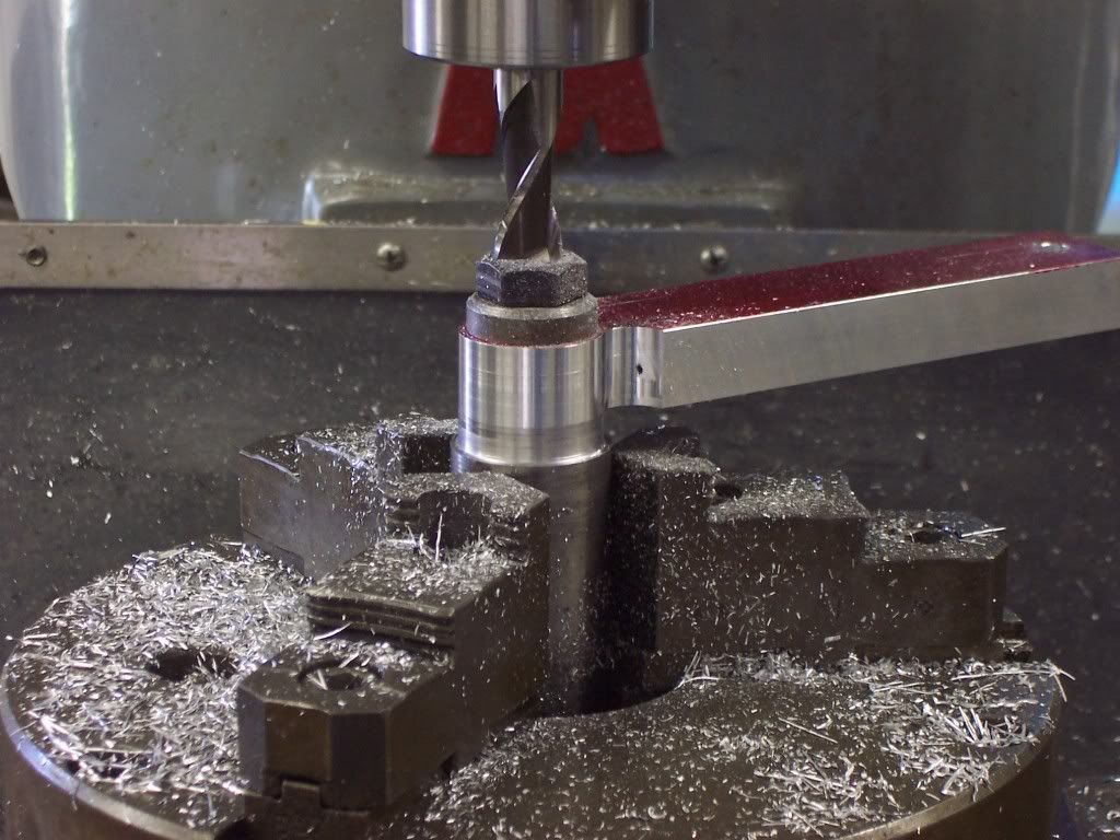
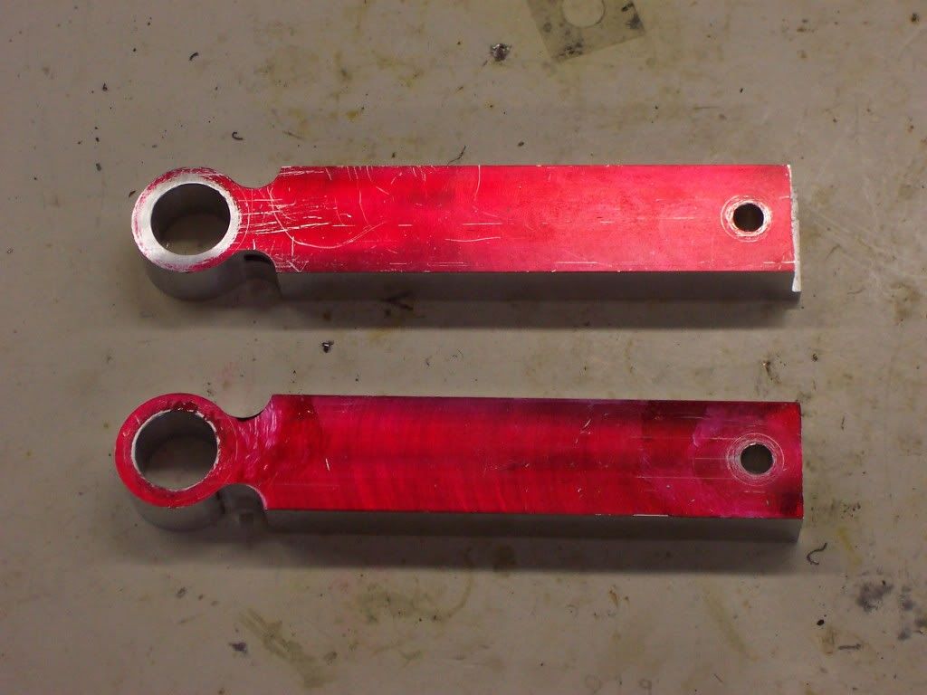
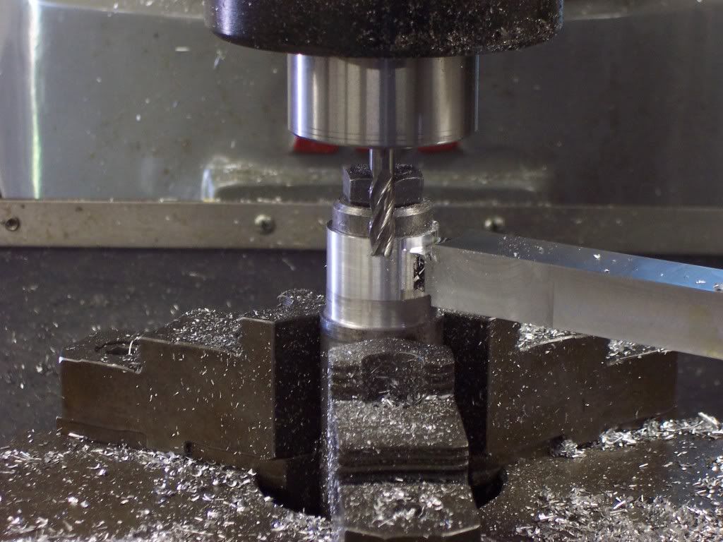
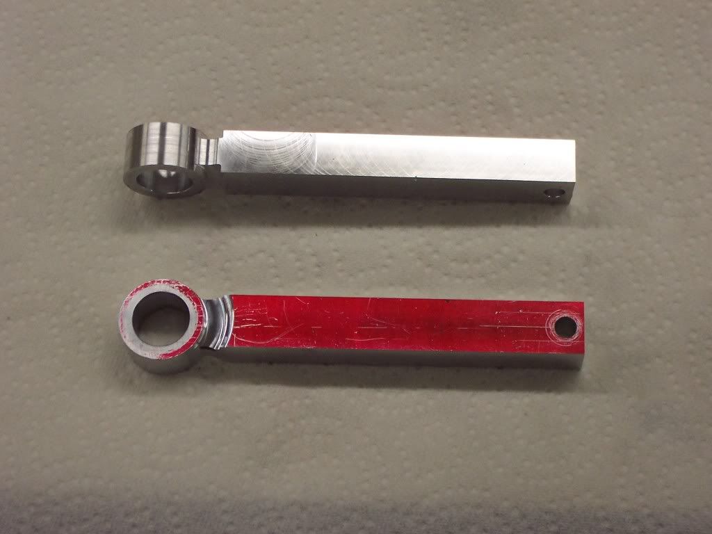
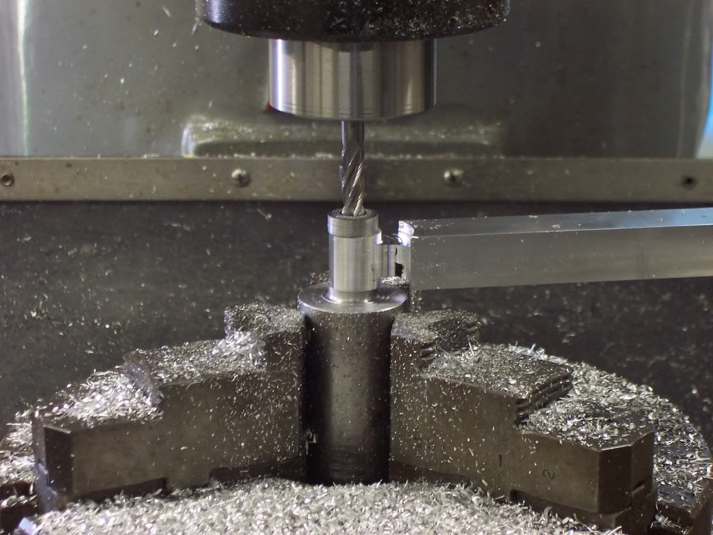
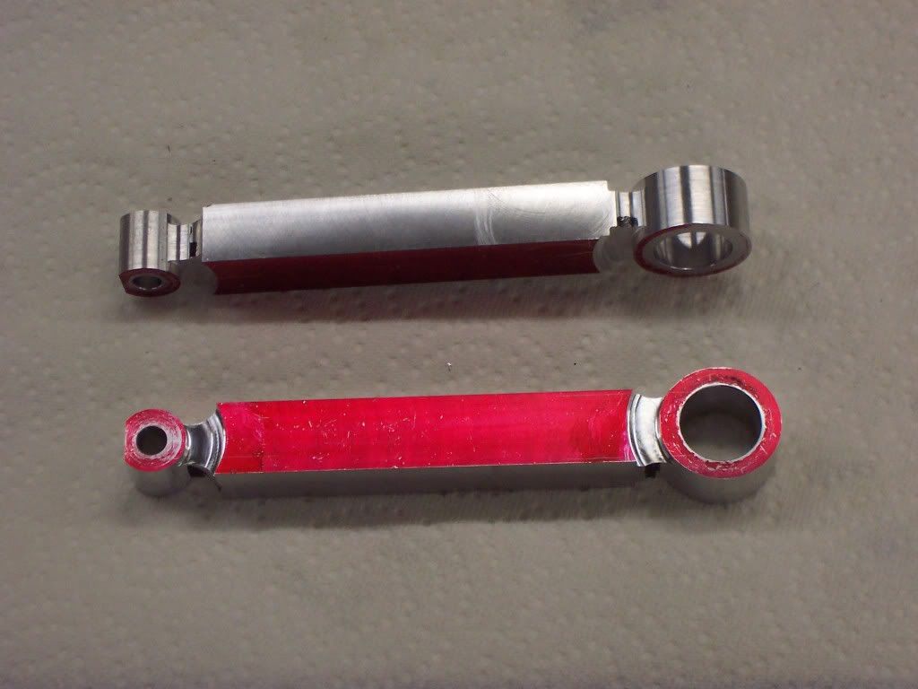
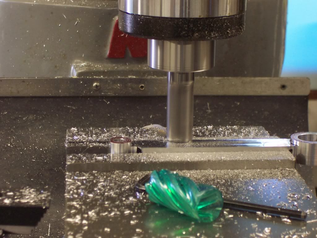
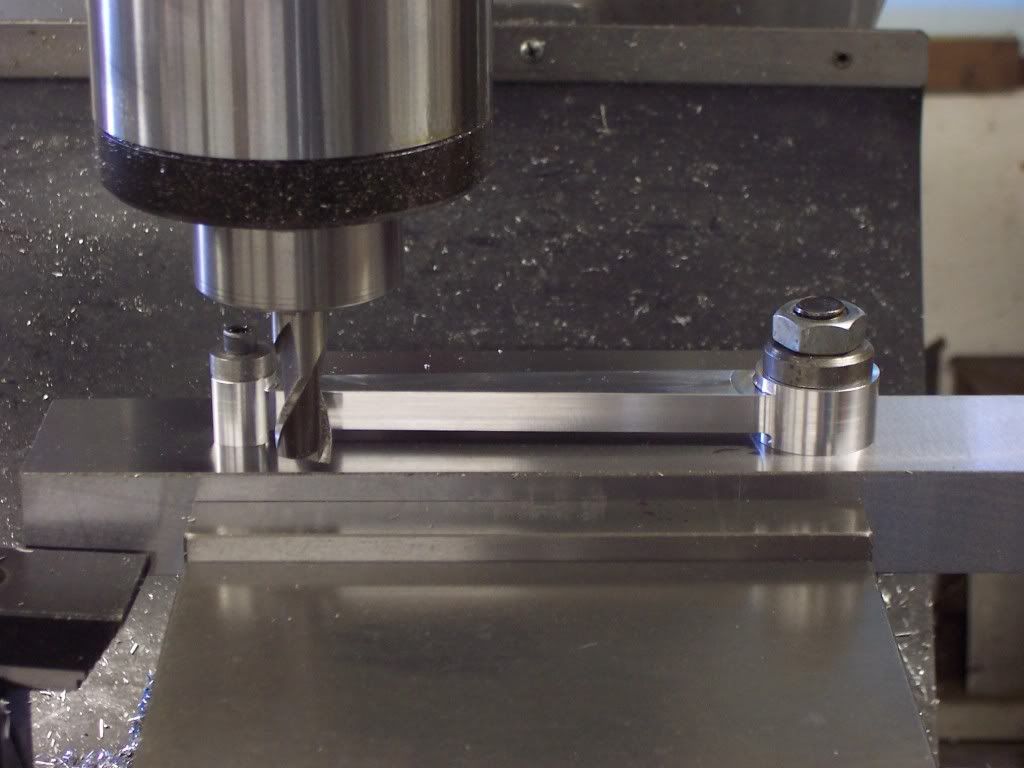
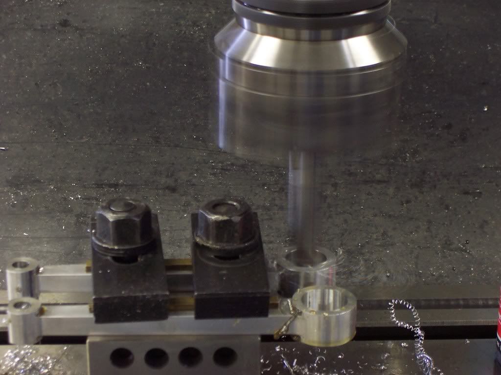
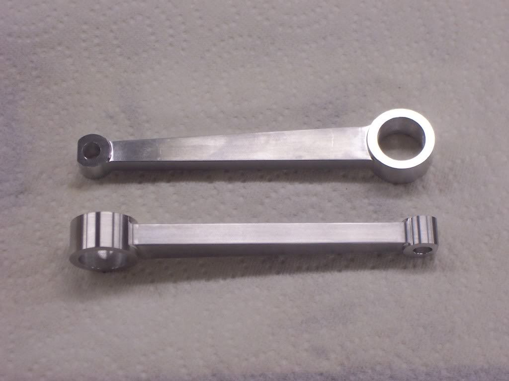
I ran a 4 axis Mazak machining center when I was last employed so getting back to the old school methods is kinda refreshing for me. I have no CNC capability now so everything must be done the old way. As this is the world in which most of us work on our engines, I'm glad my methods are of some help to others. I find that I make alot of fixtures for making parts. I try to design my fixtures so that they can be used more than once and for multiple parts. Thats my Lean training kicking in, LOL. I do wish that I had a Mazak at my disposal though, I could get alot more done.

I hope my postings will help the new machinist in his quest for which tools to buy or make and the way to use them. I'm just like everyone else, I dislike having a tool I will only use once, I would rather spend my money on a tool that gets used often.

I will continue to post my progress as it happens, kinda spotty these days but I am getting fairly close. Dave


P.S. Garry, I do build old beat up Mopars and take them to the dragstrip often. Not Ferraris or F1 mind you but still alot of fun.
 

Latest posts

Back
Top