Dave's twin

Home Model Engine Machinist Forum

Help Support Home Model Engine Machinist Forum:

This site may earn a commission from merchant affiliate links, including eBay, Amazon, and others.
I'm with Steve. I'm not quite sure how this is going to form up as an engine but the work is first rate. This one definitely has my interest.
gbritnell
 
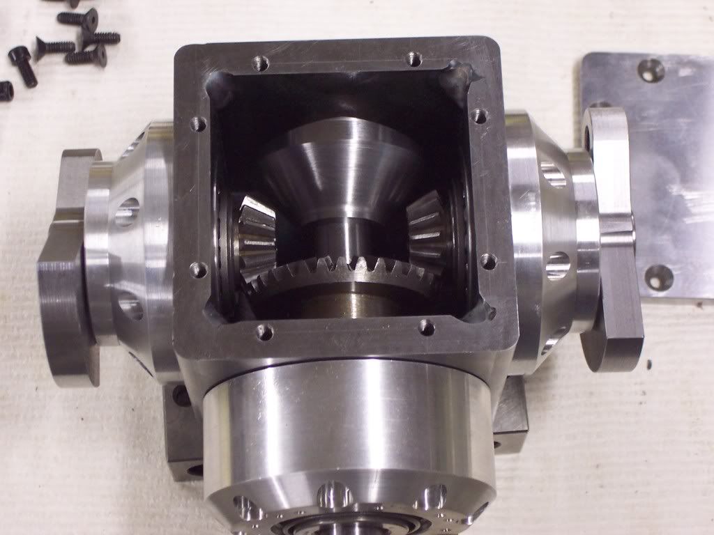
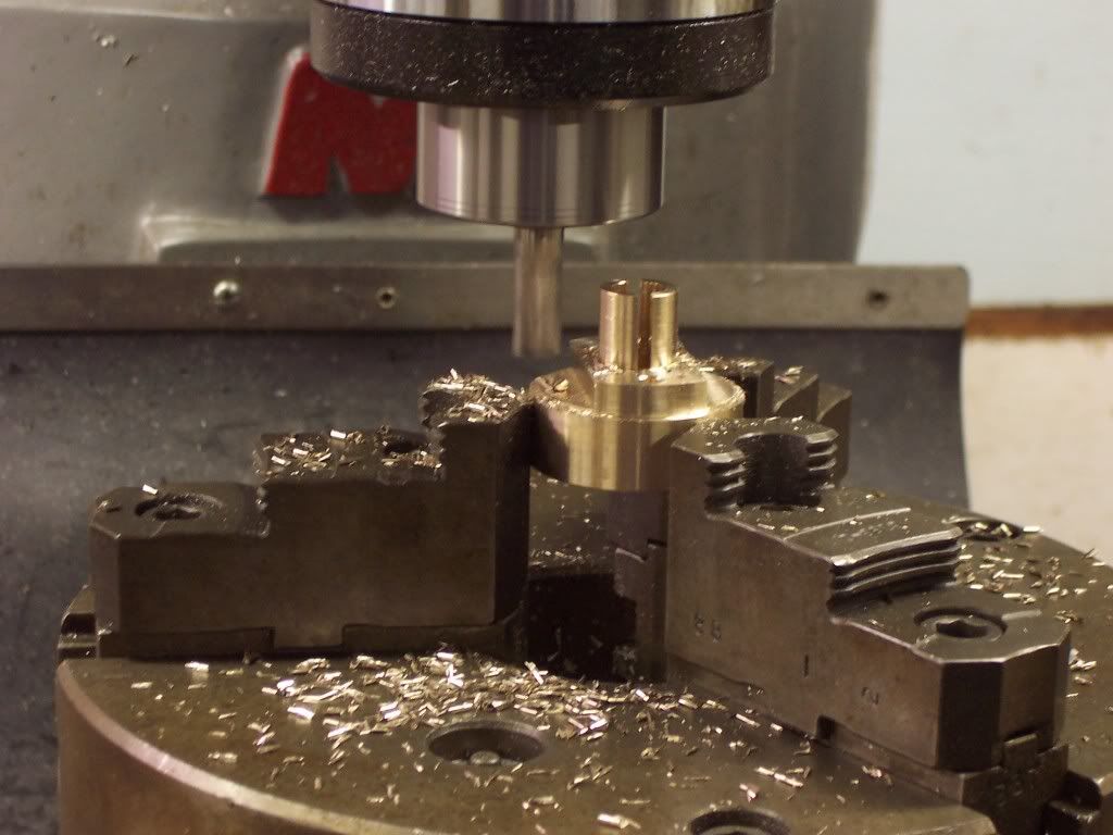
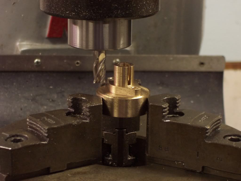
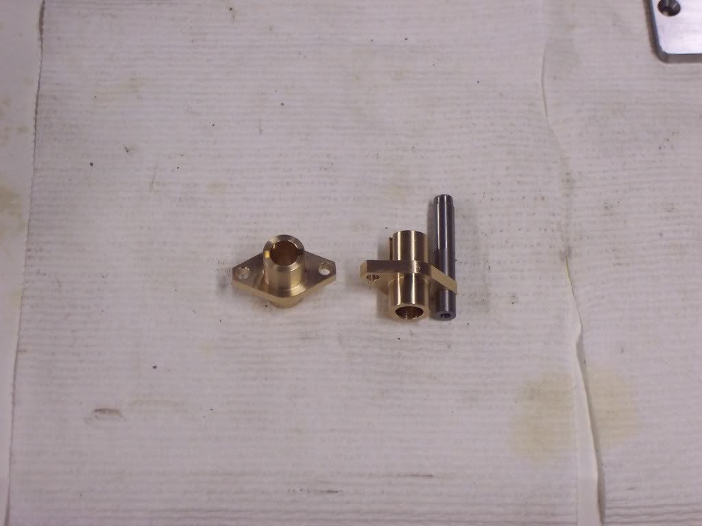
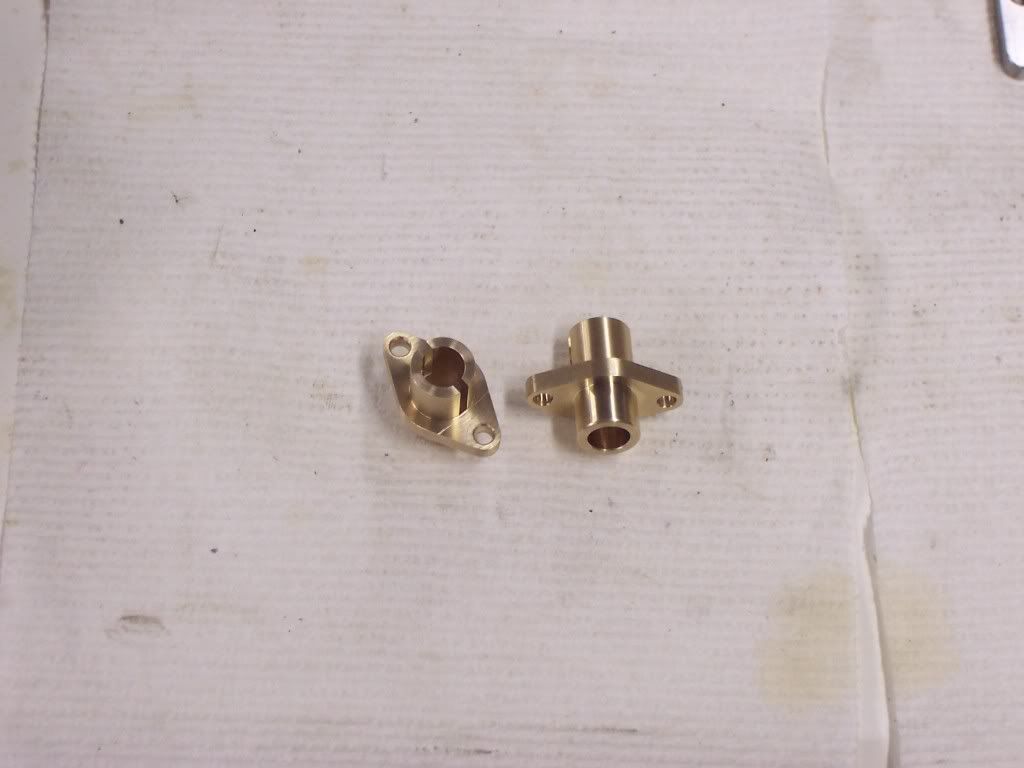
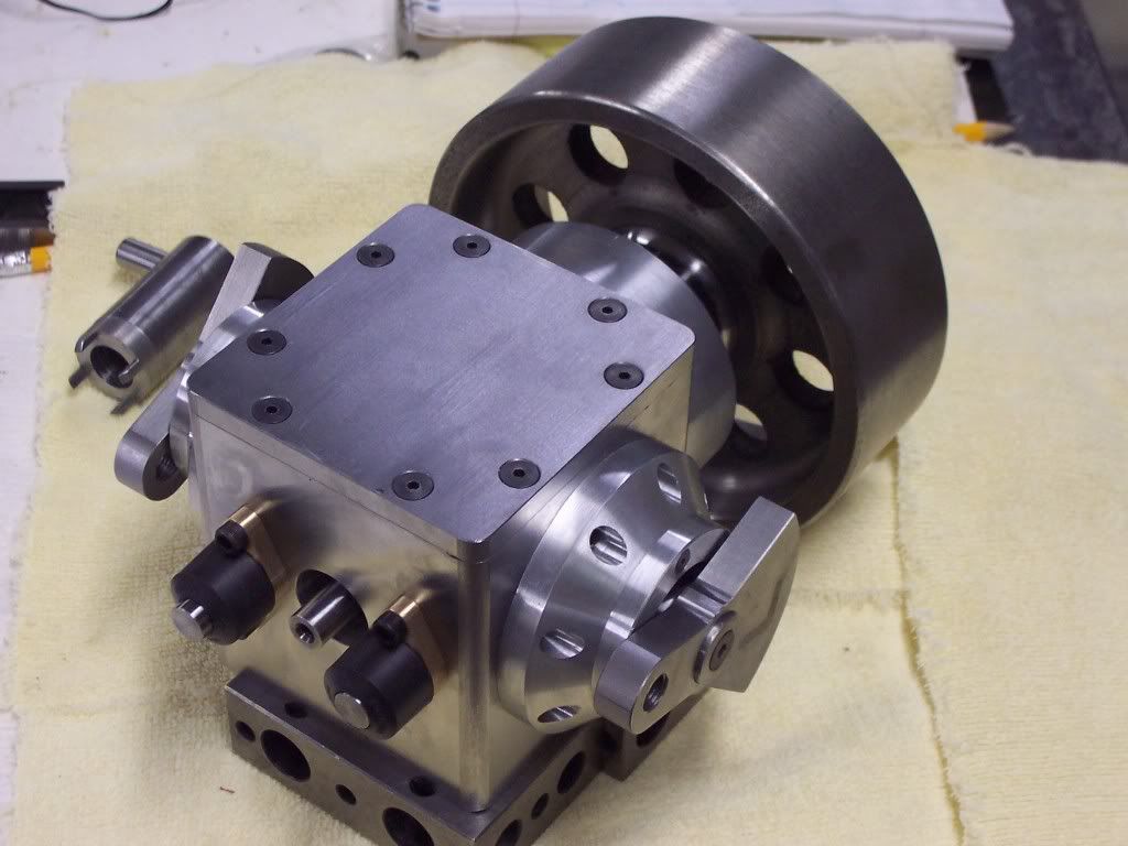
I was hoping once I got the gearcase assembled the design would start to take shape. I have some internal parts to make and then we'll start to attach a couple of cylinders to this thing. I find that I like to build things in subassemblies. I will design and build an assembly such as the bearing supports before moving to next part of the build. Building in subassemblies allows me to make changes easily and makes the assembly of the engine less complicated. If I think I'm having trouble with a certain area of the engine it can be removed without much difficulty to be corrected or replaced. Also if an idea for a feature of the engine just doesn't work, not all is lost. I can step back and go a different direction without starting completely over.

I'm glad you guys are following along, I just hope its not like when as a kid I tried unsuccessfully to jump a ditch with my bicycle with all the neighbor kids watching. At least if I fail this time a trip to the ER won't be needed. Evel Kneivel's place in history was never threatened by me and its probably good that I decided to follow a different career path. Dave
 
Made the cam ring yesterday. Started with a piece of 4140 that was preheattreated to rockwell 32 C. This pic shows the OD being cleaned up.

102_1133.jpg


Once cleaned up the material was reversed in the chuck jaws and the OD was turned to size and faced. I like to take a cleanup cut on the rough stock so I have a nice true dia to indicate on if needed.

102_1134.jpg


The bore needs to finish at .625". I bored this to .624" dia leaving .001" for sizing on the sunnen honer. If I want a bore to be concentric with an OD I will always bore and not ream if possible.


102_1135.jpg


Here we have the cam ring turned to size with a counterbore for the retainer nut and backcut for clearance.

102_1136.jpg


After parting off the cam ring from the stock in the lathe I sat the ring on the surface grinder and ground the thickness to size. Now my faces should be parallel to each other.

102_1137.jpg


I needed to make an arbor to mount the cam ring to for milling the cam surface.

102_1140.jpg


Here we have the rotary table mounted on the mill and the arbor clamped in the jaws. An indicator was used to find the center of the arbor in "Y" by sweeping over both sufaces.

102_1141.jpg
 
The first stock to be removed is the 240 degrees of cam surface that is flat. This was done by touching the endmill to the part and setting zero in "X" and advancing into the part .04". Then the rotary table was rotated 240 degrees cutting away the material. Because I want .125" of lift on the cam numerous cuts had to be taken until I got to full depth.

102_1142.jpg


It may be a little difficult to see in the next pic but the flat surface of the cam is now finished.

102_1143.jpg
 
Because this is to be an engine that runs at a slow speed I decided to use 240 degrees of duration on the cam. As the cam rotates at half crankshaft speed the cam will only need 120 degrees of duration on it. I have cut 240 degrees of material away already so now I need to cut the ramps for opening and closing of the valve. I left a flat of 10 degrees at the center of the lobe to allow me some room to blend a radius at the full open part of the lobe. That means I will have to open and close the valve in 110 degrees. Divide 110 by 2 and we get 55 degrees per ramp.

Because I want .125" of lift I will need to divide .125" by 55 to give me .0022" per degree of rotation. If I rotate the rotary table in 2 degree increments I will be able to move the table .0045" in "X" for each cut. Being that my DRO is graduated in .0005 increments this will work out well. Basically what I am doing is positioning the rotary table and "X" axis and then plunging the endmill with my power feed. All this time the "Y" axis stays at zero. Many plunge cuts later I have a ramp with some small facets to be smoothed out later.

102_1144.jpg
 
This is what spread sheets looked like before computers.

102_1147.jpg


A pic of the finished cam and the fixture for milling. This is after spending about 1 1/2 hours stoning then sanding the cam surface. I started with a hard Arkansas stone using lots of oil and then once the facets disappeared I went to wet/dry sandpaper in 320, 400, then finished with 600 wrapped around a flat bar of steel.

102_1145.jpg


And a pic of the cam ring in place on it's shaft in the gearcase.

102_1146.jpg


I used a .875" dia endmill to make the cuts on the cam surface. The radius where the flat portion of the cam meets the ramps is .4375" ( half the cutter ). I will use a roller follower with a dia of .500" so I should have a slight easing of the roller opening with the difference of radii. The proper cam shape should be 3 radii all blending with each other but I think the flat flanks on this cam should work alright. The cam and roller followers will be well lubed by gearlube splash.
 
I made the lifter guides last night. 2 pieces of 1.5" dia 660 bronze were cut off and then the first end was turned smooth until both cleaned up at the same dia. The parts were reversed in the lathe and a 1.400" dia was turned to size up to the chuck jaws. The hole for the in the gearcase will be .5625" so I will need to turn the a .562" dia stopping at .530" from the face of the part. The lifter will be .375" dia so a hole will need to be reamed in the part next. This is a pic of the part up till this point.

102_1148.jpg


Here I have taken the parts to the mill and clamped in the rotary table. I need a .094" wide slot in the center of the part for the roller to be used as a guide to keep the roller straight. First I needed to touch the top of the part with the slitting saw to give me my "Z" zero.

102_1149.jpg
 
To get the depth in "Z" we will need to add the width of the cutter (.094) to the dia of the part the was touch off of (1.400")
to get 1.494". Divide this value by 2 to get the "Z" depth of .747". The slot was cut to the depth of .554" in "X" on center with the part.

102_1150.jpg


While leaving the part in the jaws of the chuck I have mounted to my rotary table, the rotary table was now remounted in the vertical position on the mill table. The bottom face of the RT is indicated square to maintain realtive alignment. 2 holes were drilled in the part on .550" centers for clearance for 8-32 mounting bolts. To mill away the extra material not needed and to make the part look better 2 cuts were made on the flange portion of the part to leave a boss .800" wide.

102_1151.jpg


I did a small layout on the computer using cad to give me a blend angle of 27 degrees. The RT was now rotated in 5 degree increments and sweeping cuts were made until I reached 27 degrees on both sides of my zero.
102_1152.jpg


The mounting flange will be .187" thick so the cut was made deep enough.
 
All I need to do now is to face the part to length and turn a .562" dia stopping at .440" from the face. To be able to clamp on the .562" dia turned in the first op I needed to insert a scrap piece of matl in the .375" dia hole to support the walls and keep them from collapsing. Once this was done all Ineed to do is to blend the radii on the ends ofthe flange and for this I turned up a file guide the located off the mounting holes.

102_1153.jpg


Heres a pic of the 2 guides with the corners radiused with a file and then sanded on a sanding plate.

102_1154.jpg


Because my lifters will be .375"dia I figured I'd use automotive valve seals on the lifters to help sealing.

102_1155.jpg

 
Hi Dave
I wish Id read this before I made the exhaust flanges on my Wallaby,
Oh well theres always next time :big:
Fantastic as expected.
Pete
 
Very nice work Dave :bow: :bow: :bow:
You sure know how to use your tools! Looking forward to your next post.

Regards Jeroen
 
Thanks guys, I appreciate the support. I had to turn up the lifter bodies next. For these I used a piece of 4140 that was preheat treated to 32 Rockwell C. After turning to within .002 of finished size on the OD I used a square Arkansas honing stone with plenty of oil to stone the surface to within .0005" of finished size. To finish I used 320, 400, then 600 grit paper to bring the surface to a nice polish. After parting them off from the lathe and finishing to length I placed them in my square 5-C collet holder in the mill vise. The lifter was indicated to find center by sweeping over each side. Here I am using my edge finder to find zero in "X".

102_1156.jpg


After finding the edge I moved over .1875" and drilled then reamed a .125" dia hole for a dowel pin in the lifter.

102_1157.jpg


Now I need to cut the slot for the roller. For this I used a 3/32 wide slitting saw mounted on an arbor. The table of the mill was raised until the cutter just touched the part and then "Z" zero was set. I do this with the spindle of the mill in neutral and rotating the cutter by hand. I want this slot to be wider than the slot in the lifter guide to avoid interference at assembly. 2 cuts were made with there being .004" difference in "Z" height.

102_1159.jpg
 
The lifters were deburred and repolished in the lathe and then cleaned. Other than needing a dimple in the end of them for the pushrod they are finished. Next I will need to make the rollers. For these I used a piece of O-1 drill rod as I want to flame harden them for wear. The stock was chucked in the lathe and turned to within .002" of finished size and then finished to size as before. I drilled and then reamed a .126" dia hole for the pin and then parted them off. I laid them on the surface grinder with the finished side down against the magnetic chuck and blocked them in. The rollers were now ground to thickness.

102_1160.jpg


Heres a pic of the lifter components together. On the right are all parts that will make up the lifter assembly and on the left it is assembled.

102_1161.jpg
 
Now we need to ream a couple of holes in the gearcase for the lifter guides. This pic is of me indicating the roller bearing hole to find zero.
102_1162.jpg


These holes will need to be .5625" dia. First we need to spot drill with a 1/2" spot drill.


102_1163.jpg


A pilot hole is drilled.

102_1164.jpg


Drilling a 35/64 hole for the reamer.

102_1165.jpg


Now the hole is reamed with a .5625" reamer.

102_1166.jpg


There are 2 locations for the lifter guides so the other hole was reamed as before. There will be 2 8-32 holes tapped for each lifter guide. This pic shows the locations for these being spot drilled.

102_1167.jpg


I want these holes to be blind so I can keep leakage to a minimum. The tap drill was placed in the drill chuck and lowered until it touched my 6" scale and the quill stop was set. The table was raised to leave .04" in the bottom of the hole before breaking out of the other side. These holes weredrilled at this depth now.

102_1168.jpg
 
These 4 8-32 holes are tapped now.

102_1169.jpg


After a good cleaning the flywheel shaft was inserted into the gearcase and 1 lifter guide and lifter was installed.

102_1170.jpg


This basically the same pic but with the lifter on the raised portion of the lobe. You can see the lifter protruding from the guide on the left.

102_1171.jpg
 
A pic of what I have finished up till now. The flywheel on the right, the crankdisks on each side and the lifters on the left.

102_1173.jpg


I have a few things to finish up on the gearcase and will do these next. After this we will start on mounting some cylinders to this thing.
 
I just found this build and read thought the whole thing. I have learned lots from your setups and how you go about machining the different parts. You do some very nice clean work, your engine is looking great can't wait to see the end product running.
 

Latest posts

Back
Top