Building the Pumpjack

Home Model Engine Machinist Forum

Help Support Home Model Engine Machinist Forum:

This site may earn a commission from merchant affiliate links, including eBay, Amazon, and others.
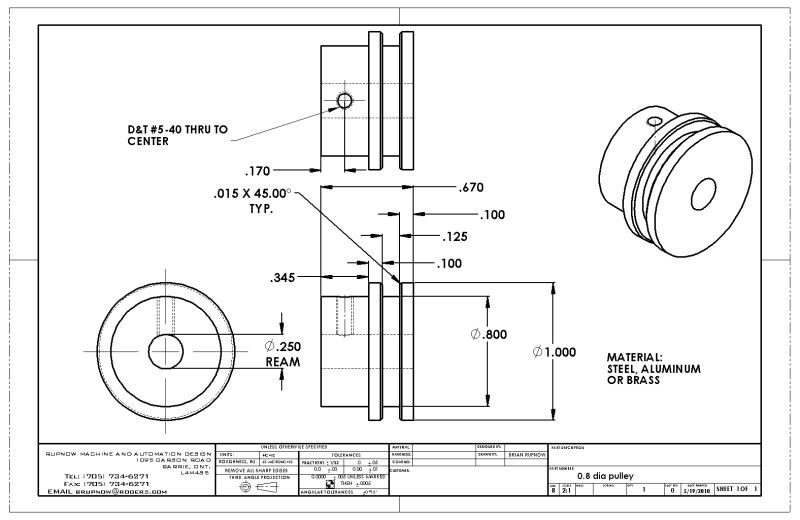
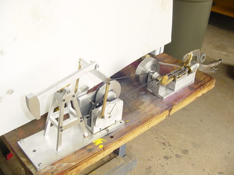
This is a pulley I just designed for it. Of course I want the pulley to be as small as possible in diameter to give a favourable ratio between it and the pumpjack pulley---BUT-- there is a caveat in doing that. If you make the pulley too small in diameter, it won't have enough contact area with the drive belt, and consequently won't have enough friction surface to drive the pumpjack.---It will just slip and spin. I'm going to take a stab at it and make a pulley as shown. Mainly because it "Looks about right" scale wise, and the fact that I have some 1" round brass and aluminum in my scrap bin.--Not much science here, but it should work.
08diapulley.jpg
 
And of course, here's what it looks like with the pulley on it.--This will be kind of a pain, because I will have to partially disassemble the engine to put the drive belt on it, ----but when I built the engine, I hadn't planned on driving anything with it. I know that I could "add on" to the outer face of the flywheel and put a pulley there, but for the sake of aesthetics, I would rather have the pulley where have shown it in the model.
ELMERS33KINDOFWITHPULLEYADDED.jpg
 
You probably have enough width in that flywheel to turn down a pulley on the outboard end Brian
 
Do you have enough room to move the flywheel to the inside and put the pulley on the outside where the flywheel is now?
You may have to mill a slot in the base for the flywheel to fit but it would save a lot of time in putting on and removing belts.
Just my cent & a half.

Allen
 
Well acturly---Those o-ring belts last forever on a model. I have to disassemble things anyways to put the pulley on, so I'll put the belt on at the same time. Those o-rings will stretch like a bugger and not lose their original "memory" for length, so they are pretty forgiving as far as selecting the "correct length" goes..
 
Brian, are you talking about run of the mill hardware store o-rings? Or the special purpose belt o-ring?

Kel
 
In this plan view looking directly down on top of the pumpjack and motor, you can see my reasoning for wanting to keep the pulley in the position I showed it, rather on the outside of the flywheel.---This centers the engine and pumpjack and lets me keep them on a common 3 1/2" base.
PLANVIEWONPUMPJACKANDELMER33.jpg
 
Fair enough, a pretty tidy solution.
 
Come and listen to a story 'bout a man named Jed----I'm starting to feel like I could be pumping that black gold, Texas tea, any day now!!! I'm up to my ears in engineering work, but took a few minutes tonight to whittle out a pulley and put it on my "Elmers #33---Kind of" engine. I wanted to be sure that it had enough grunt to drive the pumpjack, but no worries---It drives it just fine on my "Test bench".---Now if I can just find time, I will start on the base, pumprod, and wire rope harness.
pumpjackwithelmer-33001.jpg

pumpjackwithelmer-33002.jpg
 
All is forgiven matey, that pulley worked out just fine.
 
You make it seem as easy as falling off a log Brian.

Wonderful seeing it all come together. Great job, and great news on the business situation.


Kermit
 
I made some time this afternoon to machine the "riser plates" which elevate the pumpjack base off the main baseplate by 2 1/2". I did not provide drawings of these plates in the download package, because at the time I made the drawings I hadn't got this far ahead in the thought process, and because everybody who builds a pumpjack from my plans will probably have their own ideas of how to mount it to a base. There is nothing too special about these two plates, but for sake of an "in process" shot, here they are set up in the mill vice being tapped. I have also included a couple of pictures of my "Poor mans vice stop" that I cobbled together out of some angle scrap, so that I could deadend the plates against them, thus ensuring that the holes would be a consistent 3/8" in from the ends without having to measure it every time.
MACHININGRISERPLATES001.jpg

MACHININGRISERPLATES003.jpg

MACHININGRISERPLATES004.jpg
 
Well, we're almost there!!! I got up this beautifull spring morning and swore that I wasn't going to machine anything on such a lovely day------Then went downstairs and finbished the main baseplate?????? It runs, it runs very well. All thats left is the pump rod and bushing and the wire rope harness and bits, which I should get to this week. then I will make a better vido (I promise), and this project will be finished.---Brian
ALMOSTFINISHED001.jpg

ALMOSTFINISHED002.jpg

ALMOSTFINISHED003.jpg
 
Brian, I will get the polish rod and the stuffing box to tie on to the casing and a lease, couple trucks and a crain and we will be set up to be in the oil business, start slow and get used to the business before you go internationls, lathe nut
 
Well, I'm almost there. I don't have any #6-32 set screws to hold the wire rope in the brass wire rope block untill the stores open tomorrow.----and I'm not 100% sure about my wire rope. Its pretty stiff for a model. I may resort to having to get some butchers cord and dye it black to get the flexibility I need for this thing to operate correctly.
wireropeharness002.jpg
 
Actually, I just had a thought--Its pretty hard to purchase 6" of woven stainless steel cable, but my dad was a great fisheman (I'm not), and many of his "leaders" for his larger fishing lures was made of a very fine, flexible, stainless steel cable. Maybe tomorrow when I'm out picking up set screws I will drop by the fishing tackle shop and check it out!!!
 
Brian, you might investigate any bicycle shops in your area, (brake and derailer cable) or even perhaps an auto parts outlet (hood releases, throttle cable). These may be too large in strand count for what you are seeking but is another avenue to follow in chasing down materials.
I would suggest a dentist or orthodontist but the wire they use for braces etc. is most likely much too small.

BC1
Jim
 
Back
Top