Building the Pumpjack

Home Model Engine Machinist Forum

Help Support Home Model Engine Machinist Forum:

This site may earn a commission from merchant affiliate links, including eBay, Amazon, and others.
button head screw

Brian,
Great work on the pump jack. As a Texan I have grown up with these things, so I don't often think of them as being anything worthy of modelling. I see I am quite wrong.

I'm sure you are way ahead of me on this, but are you considering other types of fastening hardware than the socket head cap screws seen in the pictures?


Waiting to be told you have already got that covered,

Kermit
 
Colour me weird, if you must, but---I love Socket Head Capscrews!!!! I like the look of them, and I use them on everything I build.
 
Brian Rupnow said:
Colour me weird, if you must, but---I love Socket Head Capscrews!!!! I like the look of them, and I use them on everythinbg I build.

I'm with you, Brian (except I don't spell colour that way :big:). For model building, there doesn't seem to be any alternative that even comes close for cost and convenience of SHCS's. And they do look neat, especially when recessed.

Of course, I'm always open to suggestions.

Chuck
 
I've often wondered why so many manufacturers of fine firearms use slotted head screws in their masterpieces. Gunsmiths have to go to great lengths to keep a myriad of specialized screwdrivers on hand lest a slip mar a client's treasured gun. Surely some form of socket head (hex, square, whatever) would provide a slip-free grip - not to mention the fact that a socket will keep the driver retained when the screw is in a difficult to access location.
 
I'm a SHCS fan too. Probably dates from my early days visiting my dad's research lab where all kinds of cool one-off equipment was festooned with the things.

As for guns... tradition dies very hard in that realm. Occasionally screws are 'timed' to line up just right ($$), and for some things the slot provides a position or torque indicator (eg: adjustable sights). Many of the internal non-visible screws and more 'modern' brands have shifted to hex-head or Torx screws though.

 
And another thing... have you priced a set of miniature open end wrenches? I checked into it to see if small hex head bolts were an option. I'll tell you, you can buy a lot of allen wrenches for the price of a set of good open end wrenches in the 1/8 - 3/8 size.

Chuck
 
with the talent you guys have (chuck) ......... make your own open end wrenches.

oh..........and yes brian what a wonderful build you have going here, i just can't fathom how fast you go from idea to finished project :bow: :bow:

chuck
 
Chuck, my thought also. I wanted a set but $$$$$. I made a couple that I needed but almost everything else I use SHCS. Ironman
 
cfellows said:
And another thing... have you priced a set of miniature open end wrenches? I checked into it to see if small hex head bolts were an option. I'll tell you, you can buy a lot of allen wrenches for the price of a set of good open end wrenches in the 1/8 - 3/8 size.

Chuck

I make most of my spanners out of - you guessed it, socket head cap screws.

To each his own, I too like those little shcs's BUT they look out of place on a period engine/machine.
 
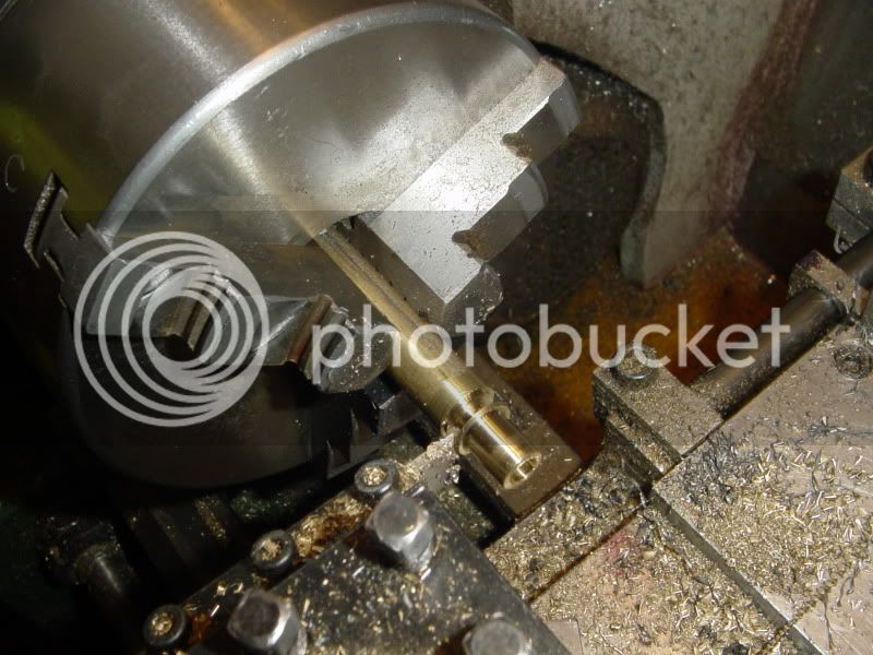
I got up early this morning and quickly whittled out a pair of brass bushings for the main counterweight shaft on my lathe. --Managed to stop and grab the camera for one "In process" shot---
BUSHINGTIME001.jpg
 
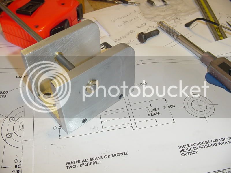
I coated the outer diameter of the bushings with loctite and installed them in the finished reducer housing. The two holes in the reducer housing were drilled and reamed in one set-up, so I know they are perfectly in line. I insert the loctite coated bushings (finger push tolerance---sliding fit) and then insert a 0.25" dia. cold rolled steel rod so that when the loctite sets up, I will be sure that the bushing bores are "in line" as well.
BUSHINGTIME005.jpg
 
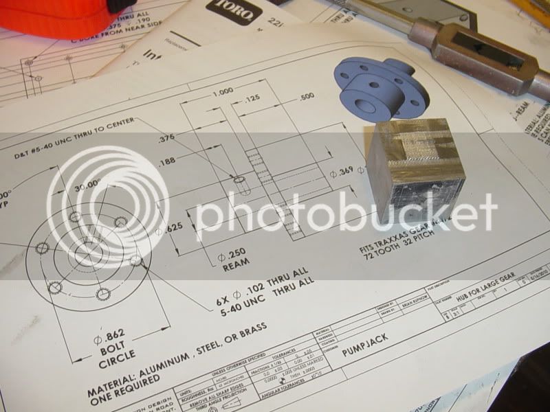
The next part of this build, the Hub for the large gear, becomes a saga in itself!!! I looked at my "stock". and the only thing i had that even come close to the right size was this ugly block of aluminum, about 1 3/8" square x 1 1/4" long.
hubforlargegear001.jpg
 
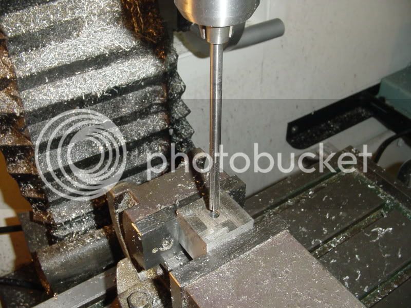
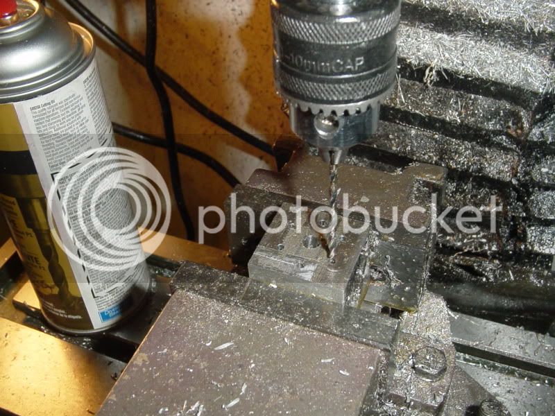
Did that scare me???-Not a bit!!! I set the bugger up in my milling vice and drilled and reamed a 0.25" center hole, then drilled (but not tapped) the 6 holes which would be tapped #5-40 later.
hubforlargegear002.jpg

hubforlargegear003.jpg
 
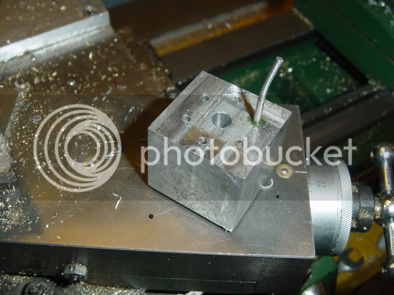
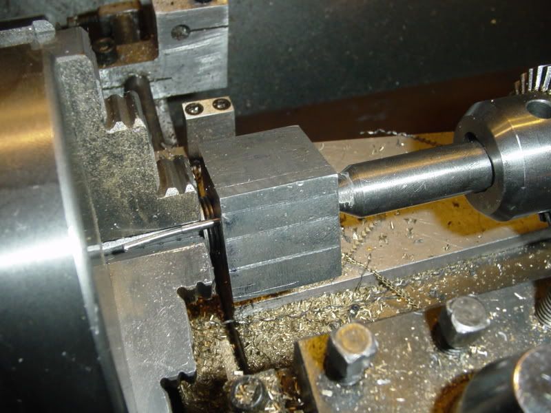
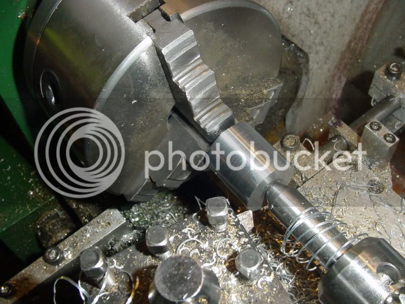
To set it up in the lathe, I needed a "drive" key to transfer the torque from the chuck to the part so I could turn it. This was accomplished by loctiting a piece of 3/32" round steel rod into one of the untapped holes.(The rod was already bent from some previous mishap). This would fit between the chuck jaws during the turning operation to be my "drive key". The part is mounted on a piece of 0.25" dia cold rolled steel shaft which extends about 2/3 of the way though the part. The steel rod is gripped in the chuck jaws and a "dead center" held in the tailstock vice is fimly seated in the side "away" from the chuck. (With a bit of white lithium grease on it to keep from burning it up.) ---Thats why the steel rod was only inserted 2/3 of the way thru---I left the last 1/3 clear to allow room for the point on the dead center.
hubforlargegear004.jpg

hubforlargegear005.jpg
 
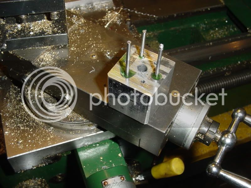
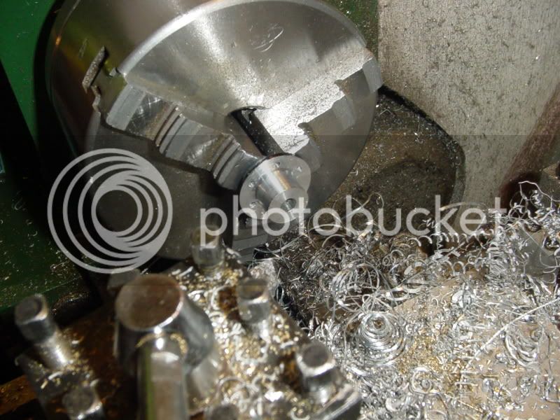
Ah well---The theory was good, but one "drive key" wasn't enough---it bent so badly that I then replaced it with 3 "drive keys"---That done the trick. It let me turn my "square" piece of aluminum into a round piece.
hubforlargegear006.jpg

hubforlargegear007.jpg
 
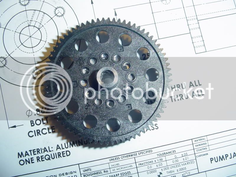
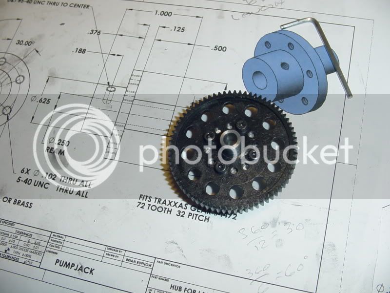
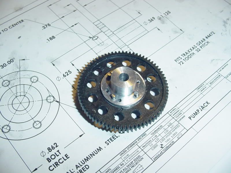
And then it was time to assemble the gear to the newly created hub for a "test fit"--And ---OH $HIT!!!!!---The holes in the new center hub don't match the pattern in the gear!!! get the gun---Shoot the engineer QUICK--Now I have to figure out if I designed the part incorrectly, or if I used incorrect settngs when I drilled the holes on the mill. I'm more inclined to think I designed the part incorrectly, as I reverse engineered the pattern from the gear when I made the drawing for the hub. --Strange thing is that out of the 6 holes, two opposing holes do actually line up alright.--Investigation to follow---
hubforlargegear010.jpg
 
Investigation completed.---Damned stupid machinist!!! The nylon Gear has 12 evenly spaced holes at 30 degrees between them. The drawing has 6 equally spaced holes at 60 degrees between them. The drawing is okay. I must have used the wrong offsets on the mill when I put the holes in the part. I can save the hub I made this morning by adding two holes to give a total of 4 holes with 90 degree spacing between them to match the gear.
 
Fortunately, the issue has been resolved!! However, let me make myself perfectly clear. This constant bickering between the engineering office and the plant floor people simply WILL NOT BE TOLERATED!!! Any further incidences of this brought to my attention will be cause for a PLANT MEETING. --The Management.
hubfinished001.jpg

hubfinished002.jpg
 

Latest posts

Back
Top