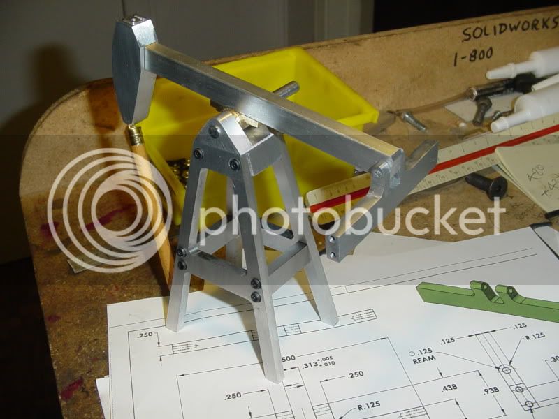
I've got a bit of "real work" in the office today, so didn't make a lot of pumpjack progress. I did get the "Beam Crosstree" finished. There was nothing too remarkable about machining it, other than the fact that I got another chance to use the "Longest, skinniest, .094" drill in the world" that I bought when building the Webster, to drill out the hole for the pin which attaches it to the Rocking beam.---And of course it was then reamed to 0.125" after it was drilled.
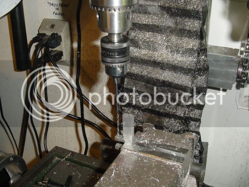
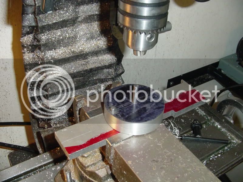
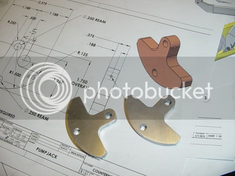
Late this afternoon I was going to start the Connecting rods that run from the counterweights up to the Crosstree---but---A check of my inventory failed to find any brass bar. So---I started the counterweights themselves. I had a favourite old uncle (The one that taught me how to drink whisky and play the fiddle), and every once in a while they'd take him in to dry him out. He was always going on about the "Steps" program at AA. So, just like uncle Jimmy, we're going to do this in "steps". ;D ;D---And here is step #1---
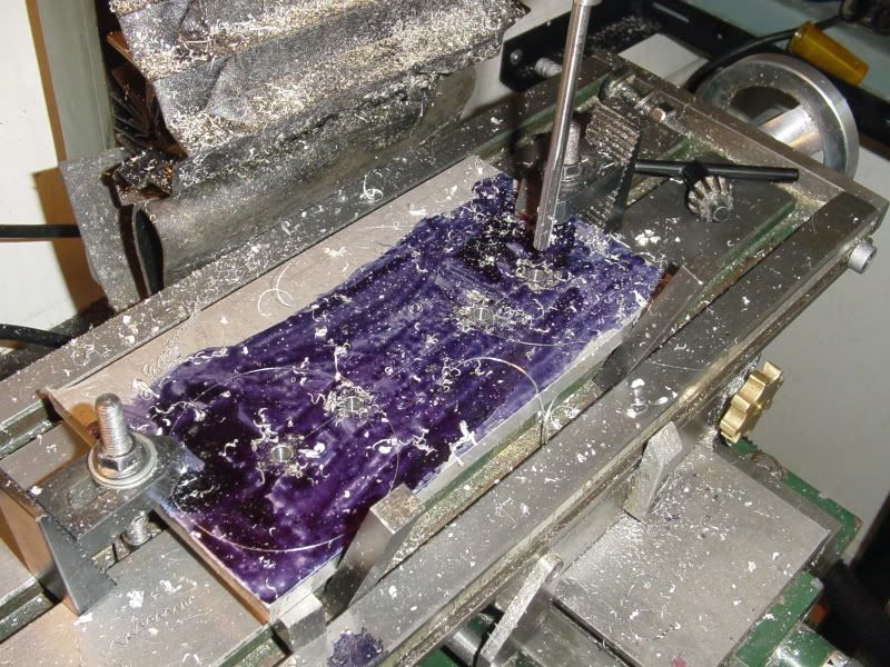
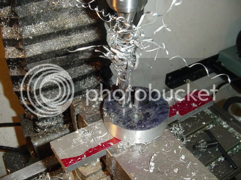
And here is step#2---(In the previous post, you can see a couple of 1/2" HSS blanks that I use for parallels between the aluminum plate and my milling table, to save from drilling holes in the table, and a second set of parallels stuck into the Tee slots to align the plate to the table)
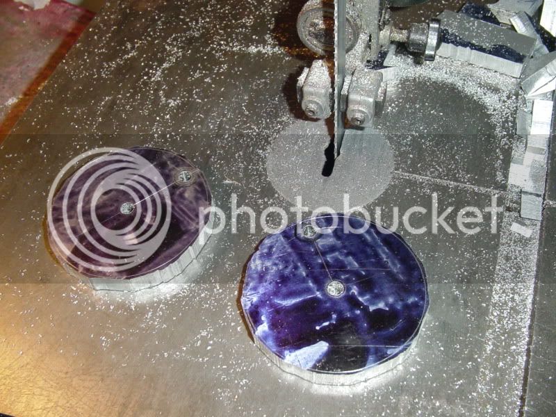
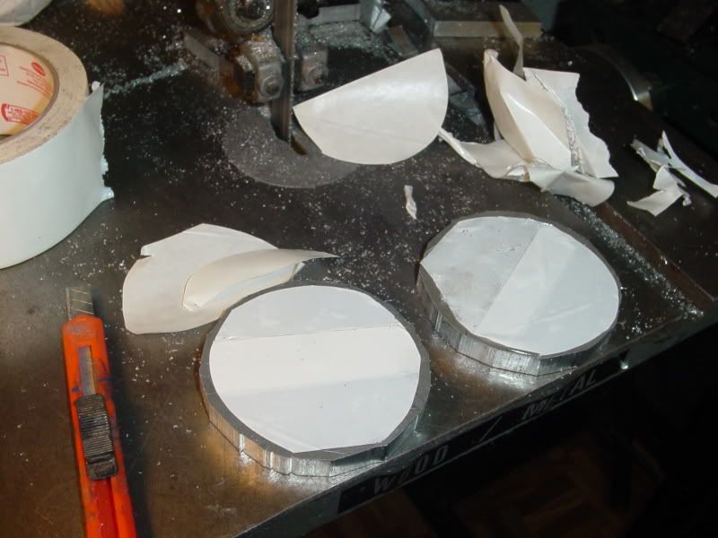
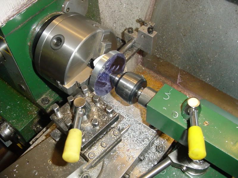
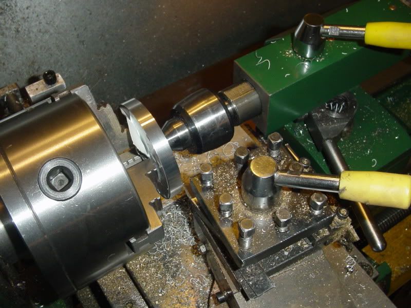
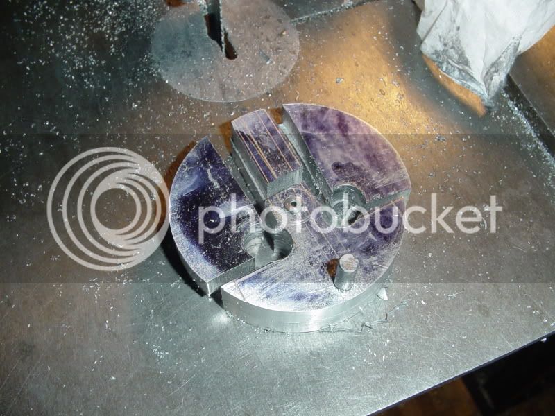
Step#3---The sticky tape caper!!! I'm sure you have all seen this trick a thousand times, but its one of those tricks that just works so damn great, I have to post it again. The sawn out pieces have a layer of double sided sticky tape applied to the side without the layout lines. The pieces at this stage are simply "roughed out" as circles on the bandsaw. I set the chuck jaws to the largest diameter they will go to without interfering with the cut which I will do to smooth the circles into a perfect diameter. I put a "live center"--(there is a bearing in it) in the tailstock and move it up to a point where I can put the point of the live center in the center hole in the part, lock the tailstock to the lathe bed, and put a good deal of pressure against the part to hold it tight against the face of the chuck jaws.--Although I have a 1/4" hole in my part, you don't need it to do this---Works just as well with a center punch mark in the piece. This uses up a lot of real estate, and if your compound rest is a wide one like mine, you will have to swing the topslide around to an ignorant angle to have room to move to move the carriage back and forth---but then you only need to move it 3/8" (The thickness of the part) and another 1.16" for clearance. This works amazingly well.
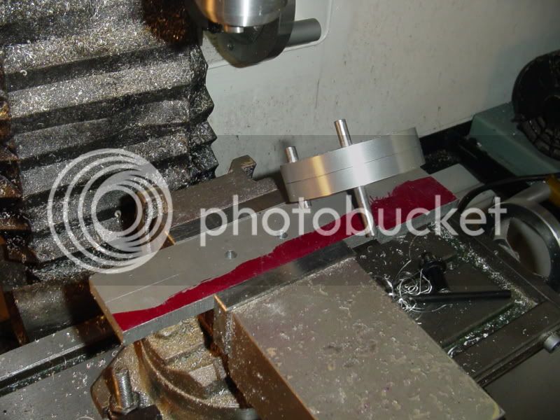
Just when I was complimenting myself on being such a clever sod, I was taken by a horrible thought!!! There are a couple of 1/4" radii on each part that require 1/2" holes being drilled thru to form them---they should have been drilled in step#1, and I forgot them. Damn I hate it when I make a mistake. I REALLY HATE IT when people are watching!!! What to do???? What to do??? I dug around in my scrap bin and found a piece of 3/8" plate, and drilled and reamed a couple of 0.25" holes through it on the same center as the holes in the parts---
Then I used a couple of lengths of 0.25" cold rolled rod to mount the parts to the scrap plate. I know the holes I drilled in the scrap plate are lined up accurately with the X axis of my mill, because I never changed any settings after I drilled and reamed them.
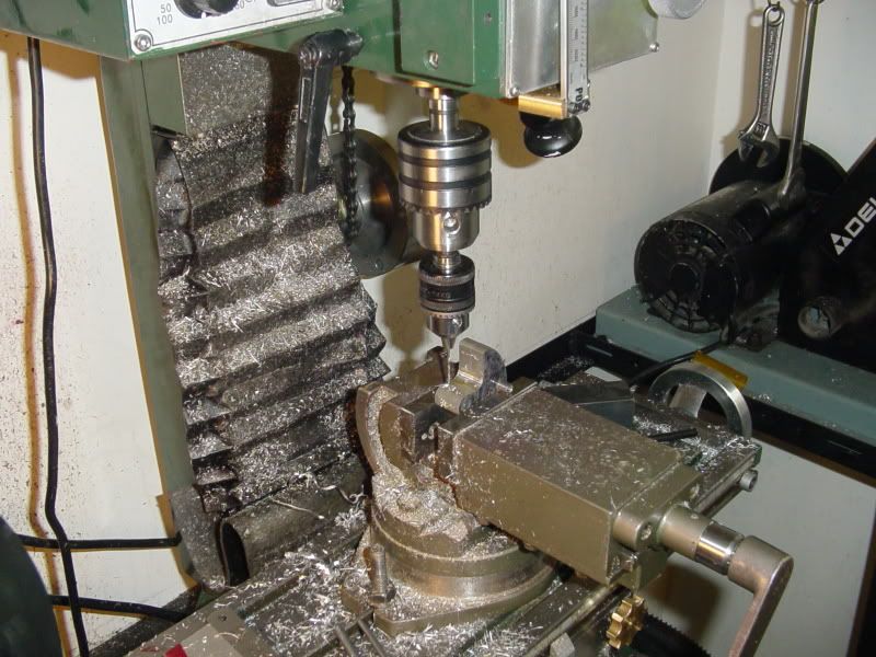
Then back over to the mill to clean everything up by milling "To the line".---Hey--this works great!!! The two pieces of 1/4" steel rod let me line everything up perfectly in the mill vice.---BONUS!!!
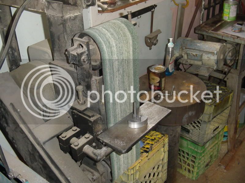
Then a walk out into the big garage and a visit to the "Monster".--This is where the majority of my "rounding off" gets done. I built that belt sander about 25 years ago, and its one of the most used tools I own.
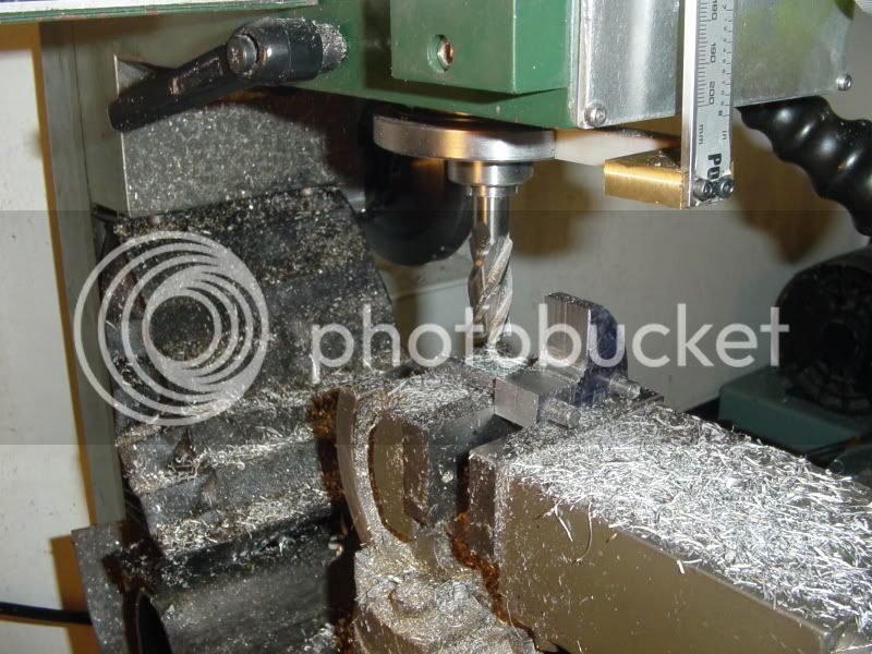
And the very last step---drilling the 1/16" crossholes which will be used to pin the counterweights to their shaft. Still using the 1/4" dia. stl. rods for alignment in the vice. Hey!!! How do you like my chuck set-up? Last year I realized that I couldn't hold anything much smaller than a 1/8" drill in my mill chuck. I had an old hand drill that had a great chuck, but the motor was burned out, so I salvaged the chuck and a couple of inches of the shaft. It works a treat, and will hold drills roght down to less than0.031 in diameter. I use it in my mill and also in my lathe when drilling really tiny holes.
The double sided tape is what transfers the torque. Without it, the pieces have a tendency to "slip" against the nose of the chuck and mar the part. Also, with the double sided tape you can take much heavier cuts than without it.
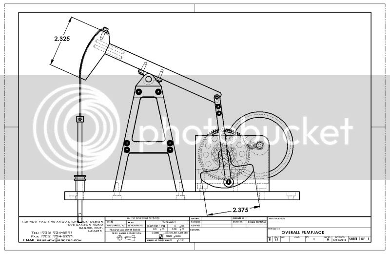
I used the "thought" method. I looked at the size of the pumpjack itself, and then, I THOUGHT----Yeah, about 3" diameter looks right.!!! This thing moves so slowly that the actual weight of the counterweight is meaningless. It just has to "Look Right".
Kcmillin--Please forgive that previous answer I was being facetious. In all of the pictures I have seen of pumpjacks, it appeared to me that the overall width of the counterweights from side to side appeared to be roughly the same the same as the length of the horsehead. I simply used that as a visual reference to come up with the counterweight size. And as I said, the counterweights revolve so slowly that it won't really matter.