Building Rudy's Steam Tractor

Home Model Engine Machinist Forum

Help Support Home Model Engine Machinist Forum:

This site may earn a commission from merchant affiliate links, including eBay, Amazon, and others.
A great job, and a nice set of photos. Very useful to us all.

I notice several of the photos have parts shown on top of nice CAD drawings. Did you re-draw the entire engine in CAD before starting?

I bought the book when it first came out, and have considered building it. Your photos are encouraging me to get started, even though Ive already built one traction engine. This one would be simple enough you could let grandkids operate it.
 
Nice looking flange, Dennis. Sometimes things that appear basic involve quite a bit of doing to actually get them to that "basic" look!

Keep on. This build is such a beauty!

Dean
 
Dean, Zee...Thank you.

Did you redraw the entire engine in CAD before starting?
Ron,
No, the plans are very good. However, lots of times I re-draw parts just to understand them better or, in the case of sheet metal, to use as a pattern. Also had to draw parts where I deviated from Rudy's plans.
Dennis
 
Lovely work Dennis :bow: - thank you for showing it!

Regards, Arnold
 
Is the book still available with the plans for Rudy's tractor??
 
Thanks, Arnold.

Faux “Case” Heater

The original Case tractors ran the exhaust pipe through a heat exchanger that used the exhaust steam to pre-heat water going to the boiler. This “heater” was built around the exhaust pipe and is visible on the left side of Case tractors as a large diameter pipe parallel to the boiler. From the heater the exhaust steam passed though the smoke box housing and finally exhausted through a blast pipe into the smokestack. The idea was that the blast created draft for the fire.

The exhaust pipe on Rudy’s Tractor is just an 1/8” brass tube that looks kind of plain. Gary Hart (ghart) came up with a neat way to add some pizzazz to the exhaust on his tractor (see his post here) and he inspired me to try to do something similar.

(By the way if anyone wants to try adding Gary’s raised CASE letters, I have his Teflon template and will mail it to the first one to ask. The only provision is that you agree to pass it on to another member when you’re done. PM me if you want it.)

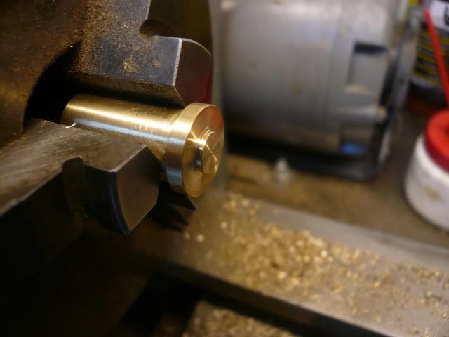
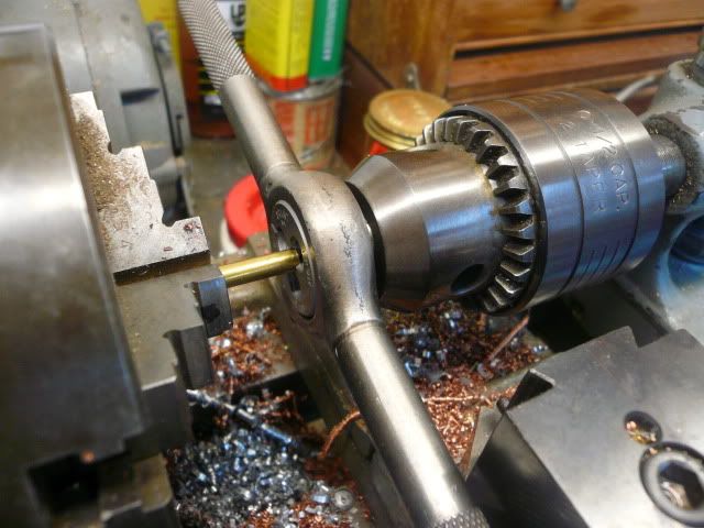
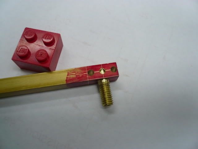
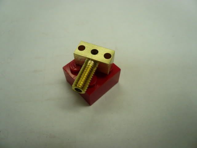
I started at the forward end with the blast pipe assembly. The blast pipe assembly begins with a drilled out semi-decorative turning,
P1050580.jpg


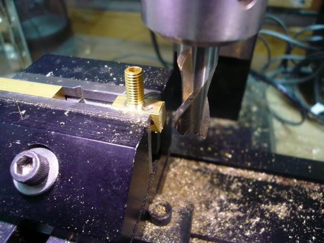
that is then cross-drilled
P1050588.jpg


to accept a 1/4” pipe that will pass through the boiler housing.
P1050591.jpg


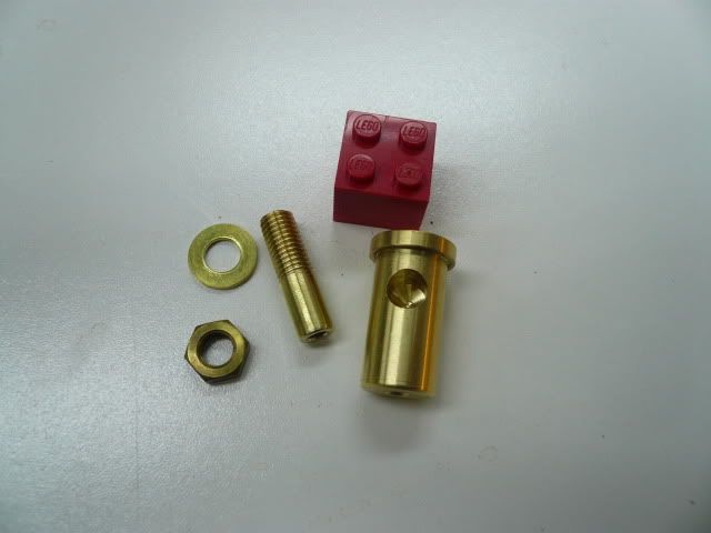
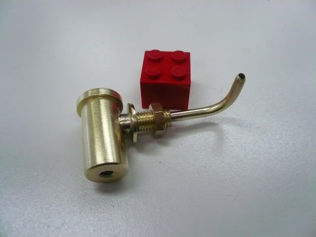
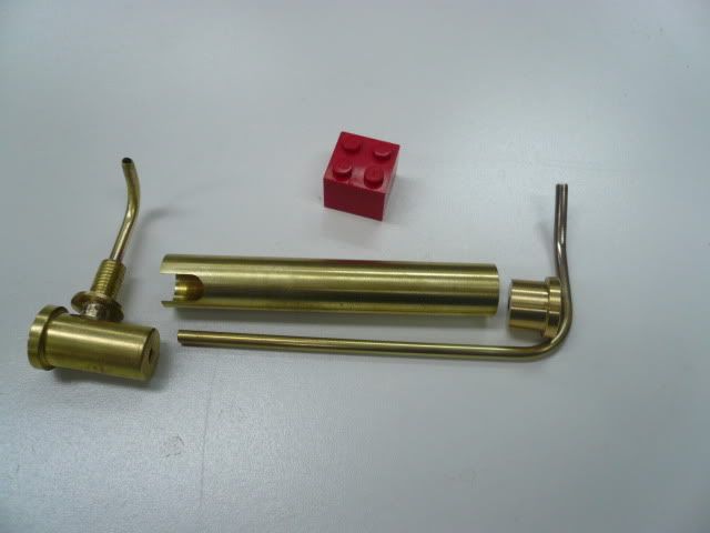
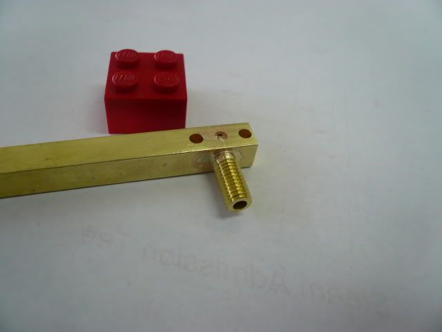
Here are the fitting pieces less the blast pipe.
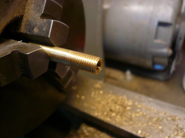
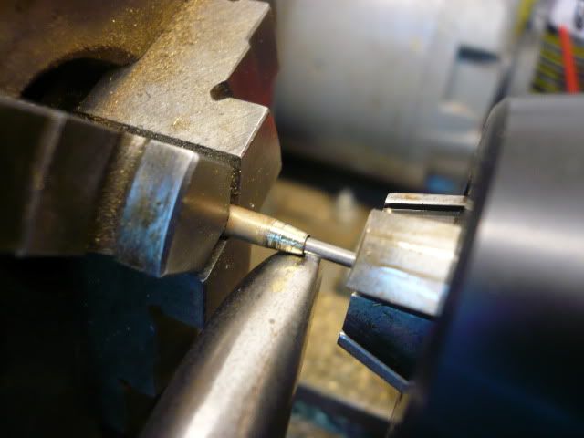
P1050596.jpg


The blast pipe is formed from 1/8” brass tubing, necked down to 1/16” ID to form a nozzle. I broke out one of my metal spinning tools and used it to form the nozzle. The steel rod is my reference and is 1/16” Dia.
P1050601.jpg


The brass has to be annealed for this to work. Also, it’s probably overkill as I think you could get the same blast effect by crimping the tube tightly around the 1/16” rod and then pulling out the rod.

After forming the nozzle, bend the brass tube to form the blast pipe and silver solder the parts together.
P1050617.jpg


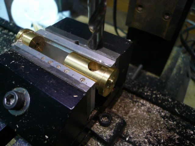
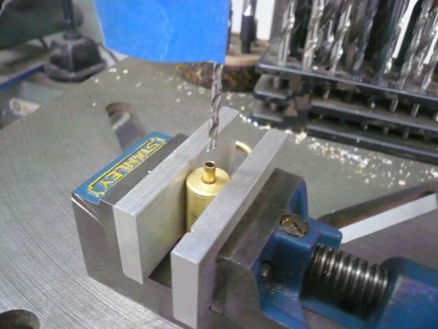
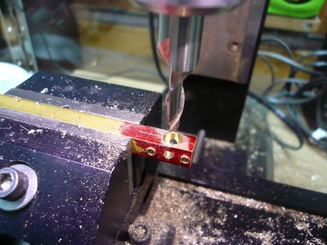
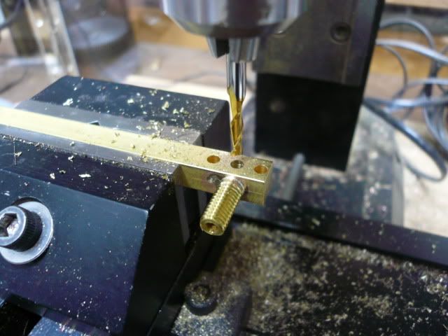
After soldering, finish drilling the cross hole to complete the passage from the exhaust pipe to the blast pipe.
P1050616.jpg


That’s the fitting clamped vertically with a loose piece of 1/8” tubing used to center the 3/32” bit. The blue masking tape is my depth gauge.
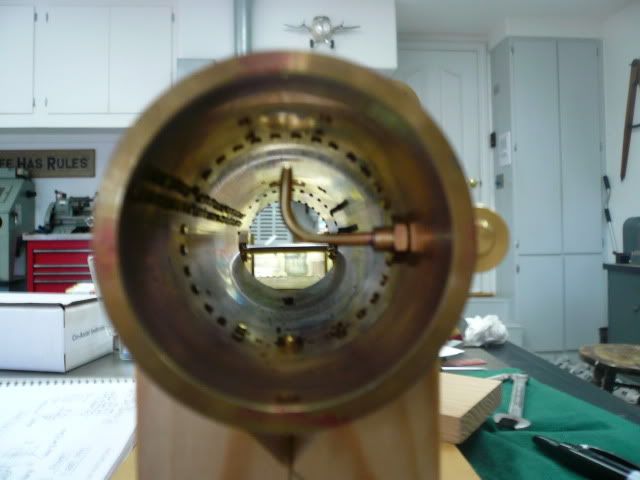
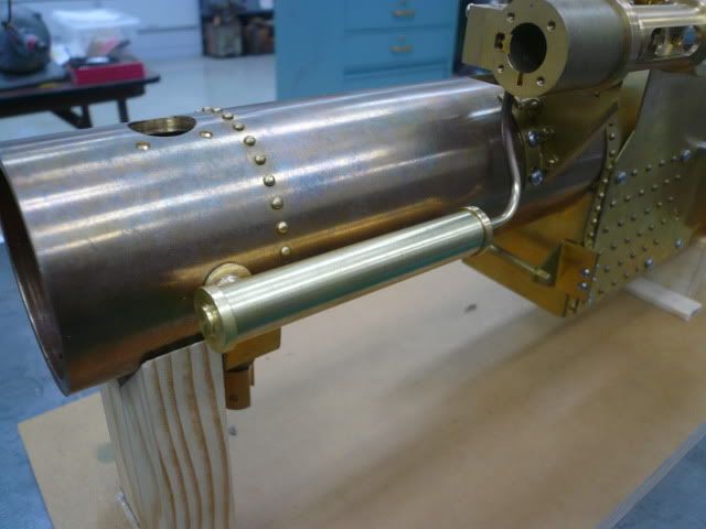
Here’s the completed fitting installed in the boiler housing.
P1050620.jpg


I still need to make some kind of contoured spacer for where the nut meets the side of the housing.

The “heater” shell is made from a piece of 1/2" brass tubing with a notch cut in one end that straddles the 1/4" blast pipe tube and keeps the shell oriented. The back end is a turned fitting similar to the front end. The exhaust pipe is formed from 1/8” brass tube to complete the faux “heater” parts.
P1050634.jpg


Here it is installed.
P1050635.jpg


It cries out for rivets doesn’t it?! Maybe later. Definitely better than just running the 1/8” pipe.

Thanks again to ghart for a neat idea.

Regards,
Dennis


Dennis

This one just keeps on getting better and better :bow: :bow:

Still following happily along, thanks for posting more!

Joe
 
I'm still with you too, Dennis. Beautiful work, throughout. Just plain ol' excellent.

Dean
 
Dennis, Dennis, Dennis

SAAAAAWWWEEEETTT Beautiful, Awsome, Any superlatives I left out.

All I can say is WOW. I'm an airplane engine guy but man-o-man that's is looking good :bow: :bow: :bow:

Tony


Looking Good! I'm in for the long run too. ;D ;D

Ron
 
Wow. Very inspiring.

[EDIT: It's a weak reply. I'm still at a loss of words when I look at the quality of work in this thread. I find myself just looking at the pics...like the fitting installed in the boiler housing.]
 
Very cool. Good work ;D.
(I agree with Carl,I just can't find words.....)
EB
 
I agree with Zee,,the work is something. I look and know I have much to learn.

Anyway its nice.

JimN
 
Once again, I want to say how gratifying (and inspiring) it is to know you guys are watching. Thank you.

Steam Admission Tee

I really should be starting on the boiler at this point, but I’m putting it off to build a few more pieces that use silver solder. I’m fairly new to silver solder and frankly am intimidated by the amount of soldering required for the boiler. I figure the more practice, the better.

The ”Steam Admission Tee” mounts on the steam chest and sends steam to the steam box and to the displacement oiler. It also serves as a mounting post for the oiler.

The Tee fabrication starts with a piece of 1/4" x 1/4” brass. I left it long to make it easier to handle. First I drilled the holes for the steam line and oiler flanges, then rotated it 90 degrees and used a 3/16” end mill to drill a flat bottom hole for the upright/steam pipe that runs to the steam box.
P1050878.jpg


The pipe is a piece of 3/16 brass rod, drilled out to 3/32” and threaded 10-32.
P1050889.jpg


After threading the pipe, I sawed it off, reversed it in the chuck and faced the end.
P1050894.jpg


Silver soldered it.
P1050896.jpg


Took it to the mill and drilled the tee passage using a 3/32” end mill.
P1050899.jpg


Then sawed it off and milled it to length,
P1050901.jpg


to complete the Steam Admission Tee.
P1050904.jpg


Thanks for following along,
Dennis
 
You're very consistent, Dennis. Your work displays a constant attention to machining details and finish.
Still following along. Still enjoying the thread very much!

Dean
 
Dennis, like Dean said - very well done indeed :bow:

Regards, Arnold
 
4156df
I hate red Dykem switch to blue please Rof}
Just kidding (not)
Beautiful work. I following all the way, That is one nice machine you have going there.

Tony
 
Gosh. I keep forgetting how small some of these parts and engines are. Dennis, like Zee and others I'm just awestruck and am just close to speechless.... Sorta. ;)
 
Back
Top