Building Rudy's Steam Tractor

Home Model Engine Machinist Forum

Help Support Home Model Engine Machinist Forum:

This site may earn a commission from merchant affiliate links, including eBay, Amazon, and others.
Progress, progress, Dennis! Looking better all the time, and it's a very enjoyable thread you have here. Nice work!

zeeprogrammer said:
Very nice Dennis.
Gee...your scrap parts look better than my 'good' parts.

Ah, Zee. You're just a frustrated metal bender.

DW
 
very nice build ,
the wheels are the worst ...lol i leave mine tell last ,makes want to get them done ha ha ha
have a great day
Todd
 
4156df said:
P1050533.jpg


Thm:

a neat approach my old brain would never have thought of. I really like it.

Kermit
 
You're doing a lovely job Dennis :bow:

Regards, Arnold
 
Once again guys, thanks for the comments. They're really appreciated.

Slip Eccentric

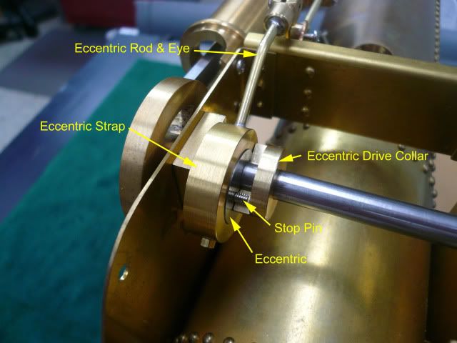
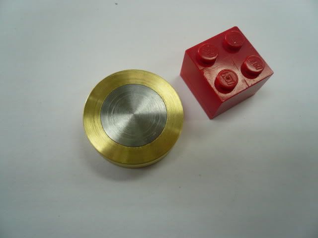
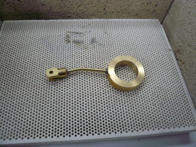
Rudy’s tractor uses a “slip eccentric” for valve motion. It allows the engine to rotate in either direction using just one eccentric. The major components are an eccentric strap, eccentric and eccentric drive collar. Here’s an “after” picture to give you an idea of what the pieces are and where they go.
P1050541-1cap.jpg


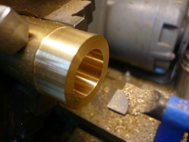
The eccentric strap is a 1” OD, 5/8” ID brass ring. The ID is a running fit with the eccentric so it should have a smooth finish. ID isn’t overly critical because the eccentric will me made to fit the strap.
P1050282-1.jpg


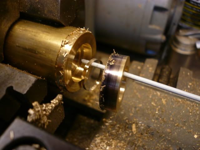
The following picture doesn’t add any info, but it’s so rare for me to have something part off cleanly that there’s no way this photo wasn’t going into the post. Why can’t it always be like this??
P1050284-1.jpg


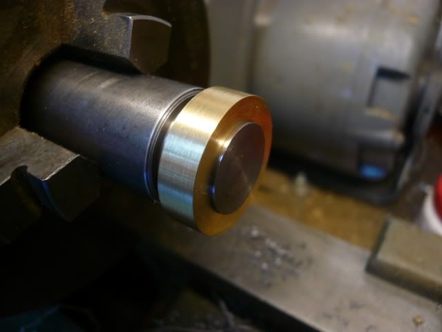
The eccentric is turned from steel and is a running fit with the eccentric strap. I used the strap as a gauge to get the correct eccentric diameter. Once the fit is good, cut a groove for the screw point that holds the ring on the eccentric and then part off.
P1050288-1.jpg


P1050293.jpg


The eccentric gets its eccentricity from a 1/4" hole reamed 1/8” off center. I used a wiggler to find the center of the eccentric using the parting lines for reference, and then the mill readout to move over 1/8”. Compared to some of the eccentrics I’ve seen on this site this is a pretty simple one.
P1050296.jpg


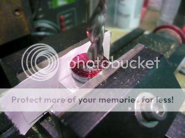
To complete the eccentric, and before removing it from the mill, drill and tap a 2-56 hole 3/32” off the center point directly opposite the 1/4" hole. This hole is for the stop pin that will engage the eccentric drive collar.

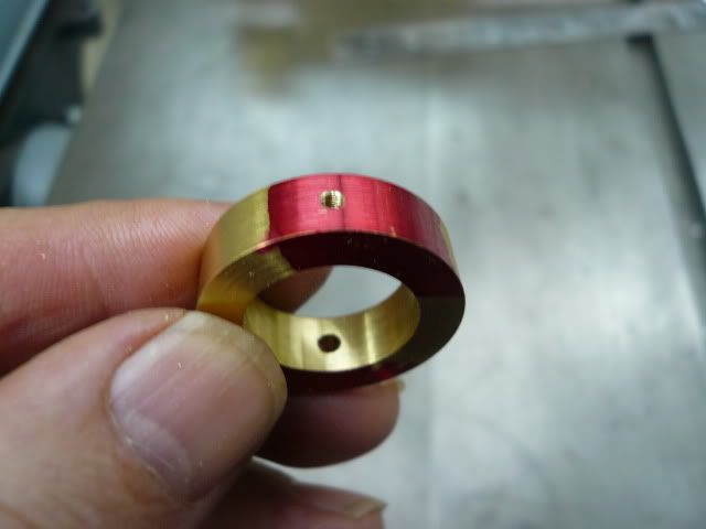
The eccentric strap machining is finished off with a drilled 3/32” hole for the eccentric rod and a 2-56 tapped hole for the screw that engages the groove in the eccentric. The screw and groove keep the ring on the eccentric.
P1050492.jpg


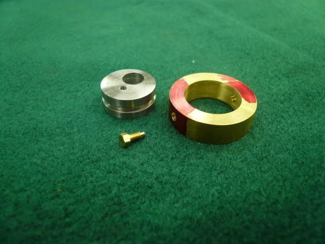
Here’s the completed eccentric and eccentric strap.
P1050498.jpg


The eccentric rod and eye are soft soldered to the eccentric ring. I used solder preforms to help control the solder.
P1050503.jpg


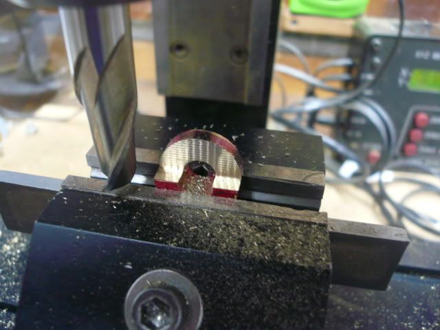
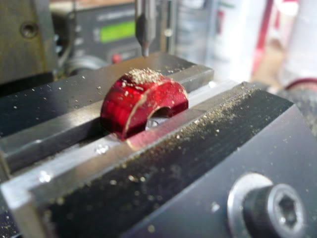
The eccentric drive collar is 1/2" diameter and 1/4" wide with a 1/8” wide step milled in it. The step depth is initially cut to 15/64” and, per the plans, may have to be adjusted later to get correct valve movement. I milled the step first,
P1050515.jpg


then reversed the collar on a sacraficial parallel to drill and tap a 6-32 hole for the setscrew that locks the collar to the drive shaft.
P1050517.jpg


And here’s the completed slip eccentric ready to install the linkage. Based on what the plans say, this will be coming apart a few times in a “slow and tedious” process of adjusting the drive collar step to get the right valve movement.
P1050541.jpg


It took me a while to get my head around how this works, but I think I’ve got it now. To reverse the engine, you stop it and manually turn the crankshaft about a half turn opposite the direction it was running. This will engage the other side of the drive collar step but will not move the valve. However, the crankpin will have moved to the other side of dead center. When the steam is turned on again the piston continues in the same direction it was, but because the crankpin is on the other side of dead center, the engine rotation will be reversed. Clear as mud, right?

Dennis
 
It sure is looking good, Dennis. Very good workmanship!
That's a pretty neat idea for a forward/reverse on the engine. It does take a little thinking to see why it would work, but I'll bet it's one of those things that once seen in action puts the ol' light bulb on upstairs. (It's always simple when someone else does it!)

Oh, by the way, nice rivets..

Dean
 
Very nice work! :bow: I really enjoy reading updates on this project.


Yep, that's what's called a "slip eccentric", a really simple way of reversing model engines. Lots of small locomotives, and my old Wilesco, use the same idea with a pin sliding in a slot.
 
Hi Dennis
I have just revised your entire post...I'm really fascinated from your working style!!!
Best regards
Paolo
 
how I missed this work in progress? ???

Dennis you're doing an excellent work and a very useful explanation of it! many thanks for showing it and many many compliments for your great work :bow:

 
It's certainly coming along nicely
 
Nice Nice Nice.
If you keep this up, I'm going to run out of things to say.
 
Not to much to post today....

Linkage

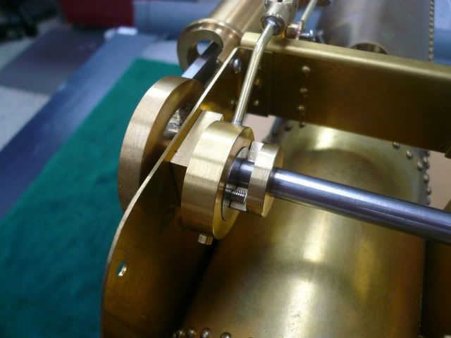
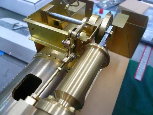
Here are the linkage bits and pieces installed on the tractor.
P1050540.jpg


The hardware is temporary and on final assembly, the screw in the center of the rocker link will be installed from this side with a jam nut on the far side.

There are a couple of deviations from the plans visible in the photo.

One is the threaded bushing that’s silver soldered to the rocker mount. The plans call for just threading the 1/16” thick mount and running a screw through it. I wasn’t comfortable with that thin of a thread, plus when I looked at Rudy’s actual prototype I noticed that his threads had stripped.

The second deviation is that I decided to make the motion support plate removable by using 0-80 screws instead of rivets to fasten it to the horn plates. The reason is I plan on running the engine so I expect to be taking it apart a lot. Being able to remove just one horn plate or the support plate should help.

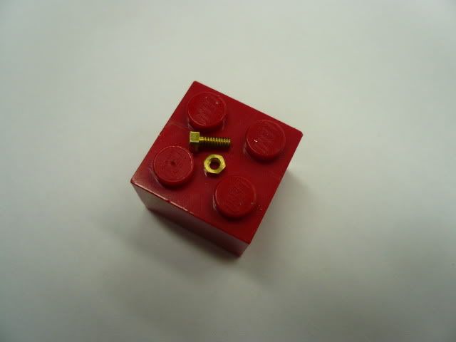
If you’ve never used 0-80 screws, they’re tiny little devils. However, they fit in the 1/16” rivet holes I’d already drilled.
P1050274-1.jpg


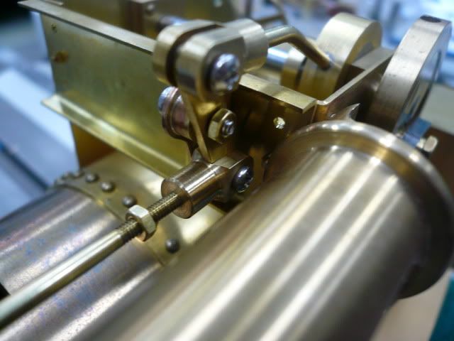
I had a terrible time getting the linkage to work. It kept binding at one point in the cycle and I couldn’t figure out why. I ended up taking the engine, linkage, piston, etc. apart three times before I spotted the problem. Can you?
P1050529-1.jpg


Yep, I hadn’t cut the groove deep enough in the valve spindle eye. A couple of hits with a file and every thing worked fine. Seems obvious now, but very frustrating at the time.

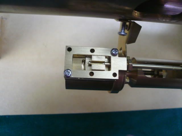
Anyway, once the linkage worked, I adjusted the valve centering and called it a day (the tractor is on its side in the next two photos).
P1050535.jpg


P1050538.jpg


Regards,
Dennis
 
Sure is beautiful, Dennis!
I looked at the pic before checking your answer about the binding. I saw the clevis touching on the pivoting bar. If that's what you meant, I caught it! I can't find my own mistakes though...

Dean
 
You kept going! And like I said...I've run out of things to say.

Very good work. Very good thread.
 
looking great. hopefully I'll be following along before too long. Just snagged 3' of 4.5" tube to make wheels from.
 
Well, Shred, that should be enough! ;D How many tractors did you say your're making?
Dennis
 
4156df said:
Well, Shred, that should be enough! ;D How many tractors did you say your're making?
Dennis
:D Yeah, I went to "The Pipe Ranch" and asked for a foot of 4". They went to the short-end pile, picked up the shortest piece and handed it to me. I figure I'll have several feet of indestructible small-stock racking in a bit..
 
Just went back through the entire thread. What an impressive project! Very nice work.

Chuck
 
Thank you for the positive encouragement. I really appreciate it.

Short post today.

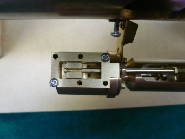
I started work on the exhaust/blast pipe. The exhaust pipe is 3/16” diameter brass tubing and is fastened to the valve box with a flange and two 2-56 screws. It runs from the valve box along the side of the engine, through the boiler casing and exhausts through a blast pipe into the smokestack.

Rudy made his flange by silver soldering the tubing through a hole in a flat piece of brass. It’s a neat, compact way to do it, but I’ve always admired the separate flanges I’ve seen some of you do. This seemed like a good place for me to try making one. The method I used was shown by Bogstandard in one of his long ago posts.

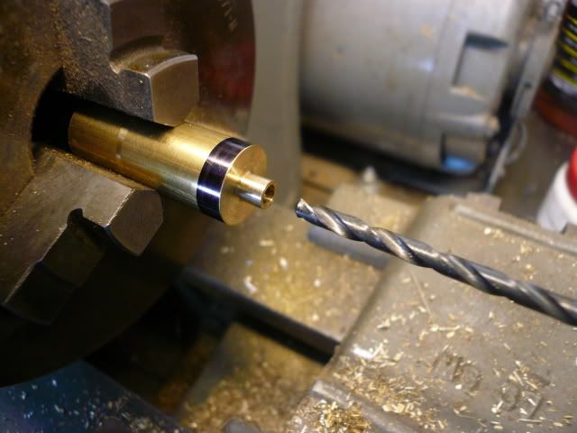
The flange starts out as a turned nipple with a 3/16” ID that matches the mating tubing OD.
P1050547.jpg


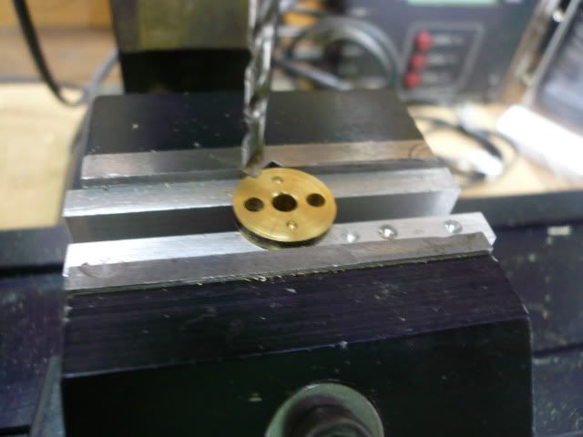
After parting off, clamp the part in the mill, center it, and use the X axis to locate and drill the two clearance holes for the mounting screws.
P1050552.jpg


The two dimples in the above photo were due to me thinking I could eyeball the center of the part. Will I ever learn? They’ll be cut off later, so no matter.

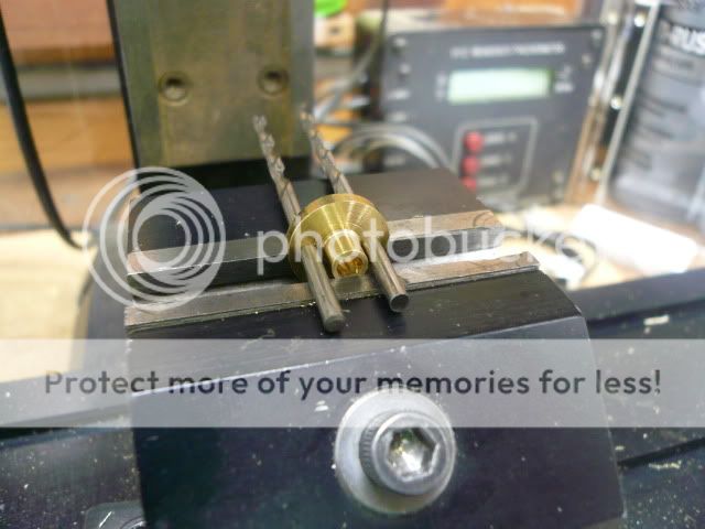
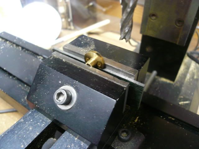
Now, here’s the neat part (Thank you, Bogs). Insert two drill bits the same diameter as the mounting holes and use them to orient the part in the vise so that the edge of the flange will be parallel to the center line of the mounting holes.
P1050555.jpg


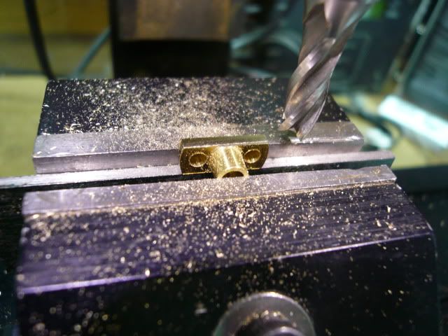
Mill the edge off to a depth you like and rotate the part to remove the other edge. This could be done using the drill bits for alignment, but for this particular flange, there wouldn’t have been much for the vise to grab on to. Instead, I put a suitable parallel in the vise and use the just milled edge as a reference.
P1050563.jpg


Mill the second edge to the same depth as the first.
P1050567.jpg


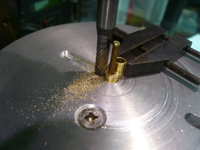
I liked the look of the flange at this point and almost left it. However, not being one to leave well enough alone, I decided to round the corners.
P1050569.jpg


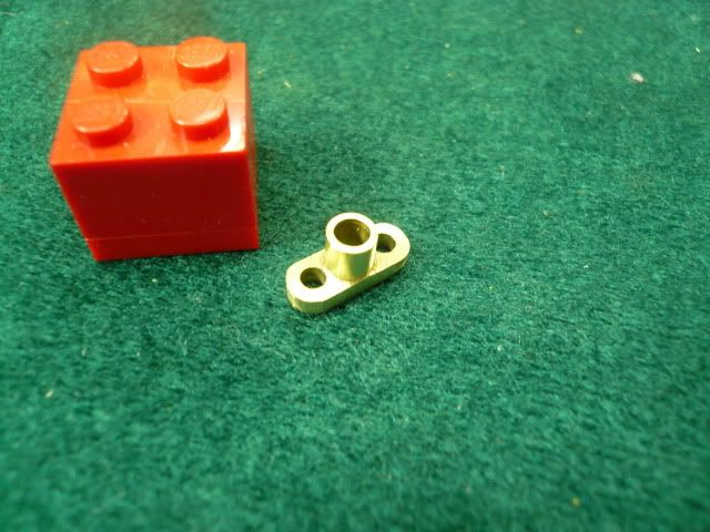
And this is the finished flange.
P1050572.jpg


Hope this wasn’t too basic. I thought It’d be worthwhile because this part has application on many engines. It’s certainly one I expect to be making more of.

Regards,
Dennis


Latest posts

Back
Top