arnoldb
Well-Known Member
- Joined
- Apr 8, 2009
- Messages
- 1,792
- Reaction score
- 12
Thank you Zee - I'd get fired in a production environment though; I work waay too slow for that :big:
Dean, thank you. Yes, I'll lap the mating surfaces - not to a mirror finish though; only till operation is smooth. The fine "grooves" from facing the top of the body will help with oil retention.
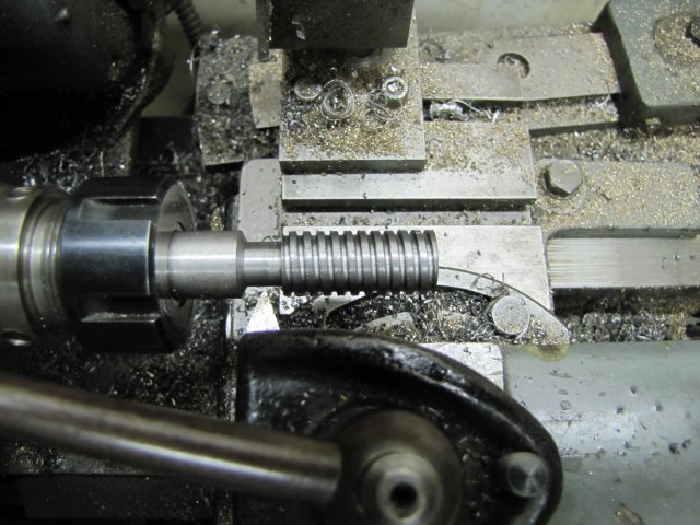
I do like single pointing; its extremely satisfying to end up with a good thread. Many people dread single pointing, but I think its one of those jobs where its mind over matter - and a couple of simple rules to follow. Maybe I must post a full write-up on the way I do it at some point; any takers out there ?
Thanks Phil ;D
Helder, thank you. It's an angular contact bearing. It is mounted the correct way around as shown but maybe counter intuitive without the rest of the assembly. The outer race will be pressed into the top of the base from the bottom (underside). When the table is then installed from the top, the nut is used to screw up against the inner race of the bearing to pre-load it - This should become clearer when I get to the point when I start to fit things together.
Today's little bits...
First thing, I wanted to get the top plate of the base bolted to the frame; I'd marked it out already for the bolt holes, so I just needed a way to make the whole lot stay together for drilling and so on. I sawed two longish strips of 20x5mm flat bar off a length I keep handy for incidental needs such as this. Both strips were drilled for clearance holes for some 6mm cap screws, and then the top plate and frame were bolted together like this:
The bottom strip of plate is through the mounting slots of the base.
Then I clamped the whole lot down square on the mill table; there is a clamp on the hidden side in the other groove of the mill table:
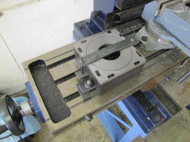
I forgot to put a piece of paper below it....
Then I started drilling all the holes. Even though I had laid out the hole locations, I decided to go for X and Y coordinates using the handwheel calibrations - as each hole had to be center drilled, then tap size, for clearance trough the top plate and finally counterbored for recessing the M5 cap screws I would be using. So I located the edges of the right front corner the primitive way; with a bit of 6mm silver steel chucked and a piece of paper. (Aside - I've had some great news today; I will be the owner of a proper edge finder soon ;D - THANKS MATE!) Then I started counting turns and reading handwheels while center drilling each hole, and jotting down the figures on a bit of paper. Here all the holes are drilled to tap size (4.2mm):

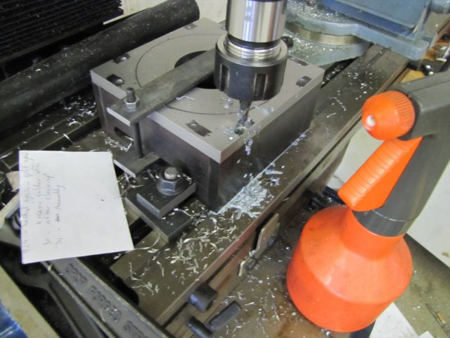
That lot was followed by a 5mm drill just deep enough to provide clearance through the top plate. The heads of the cap screws measured out at 8.4mm in diameter and just below 5mm high, so I used a 9mm mill to counterbore the clearance holes 5mm deep. My advanced lubrication delivery system is the orangey bottle in the right of the photo :big: :
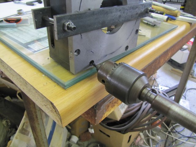
With all the holes I needed to tap full of swarf from the counter boring, I used a drill chuck with a 4mm drill to manually clean out the holes. Just plonked the lot on its side, and by hand turned the drill in each hole to get the swarf out. Photo without the hand that should be turning:
Then I sat down on the bar stool I keep handy (my "working table" is a bit high), and tapped each hole. The 5 mm clearance holes in the top plate are excellent tap guides to keep things square when starting with the first tap, so nothing fancy required as guide. Just manual work ;D. I'm due for a new set of M5 taps though; I could feel these starting to struggle, but they have tapped many tens of holes in the last two years... All bolted together:
Things went well didn't it ??? - Well NO - If you look carefully at the left hand hole in the top row in the picture, you'll just see the mark where the end mill wandered when the lot came loose on the mill table. Remember I said I didn't add the piece of paper below when clamping ? :wall: Fortunately I could recover; and another mark on the table to serve as a reminder... I think I can still hear some bad words echoing around the shop; fortunately Shrek was out of earshot!
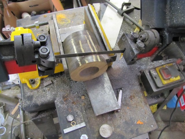
With the base finally together, I started on the gear. A slightly oversize chunk of the phosphor bronze getting sawn off:
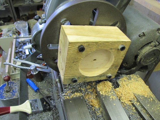
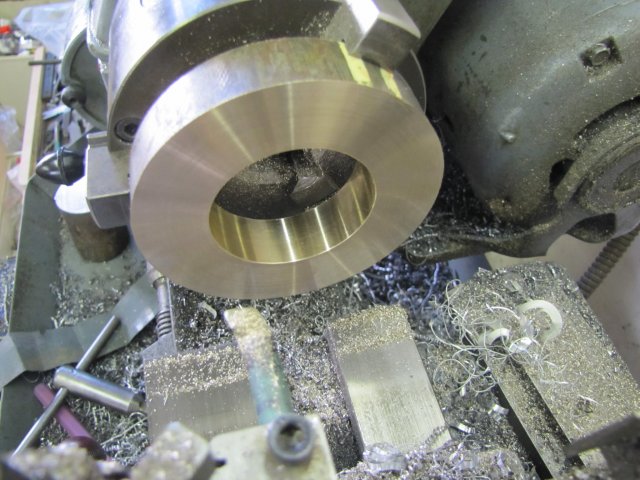
Then faced and bored in the 3-jaw:
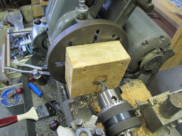
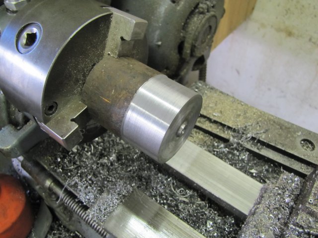
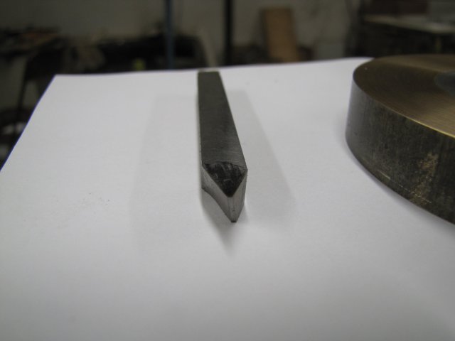
Next a section of the left-overs from that old big bolt was turned down for a press fit in the bore in the PB ring:
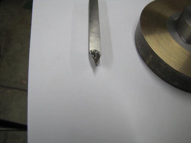
Then I sawed off the turned section of steel, and dumped it in my freezer on top of some ice for 10 minutes - it was nice and cold then ;D
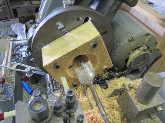
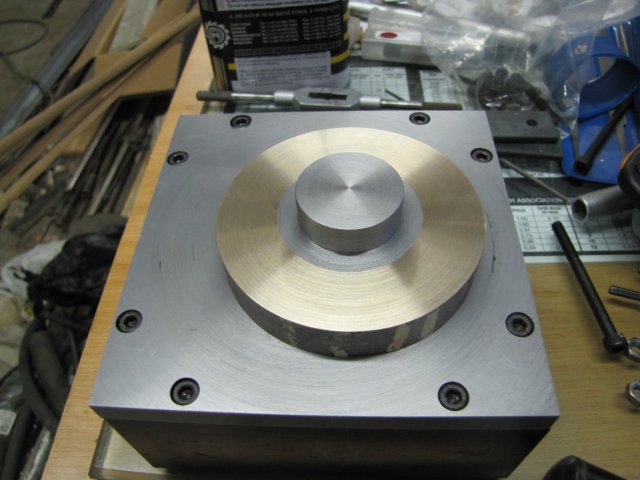
It pressed into the ring in the bench vise without too much effort, enough to give a good press fit, but not so much that the PB ring would crack:
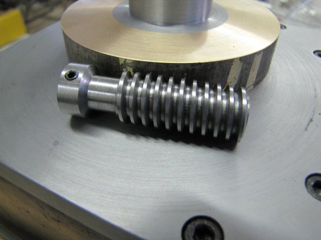
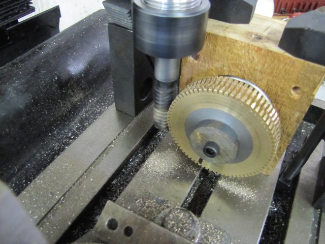
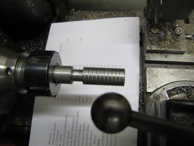
Some more turning, and I have the makings of a gear:
I need to double check some calculations now, and run through the needed steps in hobbing the gear in my mind, so updates might be a bit slow for the next couple of days. Think thrice - machine once...
Regards, Arnold
Dean, thank you. Yes, I'll lap the mating surfaces - not to a mirror finish though; only till operation is smooth. The fine "grooves" from facing the top of the body will help with oil retention.
I do like single pointing; its extremely satisfying to end up with a good thread. Many people dread single pointing, but I think its one of those jobs where its mind over matter - and a couple of simple rules to follow. Maybe I must post a full write-up on the way I do it at some point; any takers out there ?
Thanks Phil ;D
Helder, thank you. It's an angular contact bearing. It is mounted the correct way around as shown but maybe counter intuitive without the rest of the assembly. The outer race will be pressed into the top of the base from the bottom (underside). When the table is then installed from the top, the nut is used to screw up against the inner race of the bearing to pre-load it - This should become clearer when I get to the point when I start to fit things together.
Today's little bits...
First thing, I wanted to get the top plate of the base bolted to the frame; I'd marked it out already for the bolt holes, so I just needed a way to make the whole lot stay together for drilling and so on. I sawed two longish strips of 20x5mm flat bar off a length I keep handy for incidental needs such as this. Both strips were drilled for clearance holes for some 6mm cap screws, and then the top plate and frame were bolted together like this:
The bottom strip of plate is through the mounting slots of the base.
Then I clamped the whole lot down square on the mill table; there is a clamp on the hidden side in the other groove of the mill table:
I forgot to put a piece of paper below it....
Then I started drilling all the holes. Even though I had laid out the hole locations, I decided to go for X and Y coordinates using the handwheel calibrations - as each hole had to be center drilled, then tap size, for clearance trough the top plate and finally counterbored for recessing the M5 cap screws I would be using. So I located the edges of the right front corner the primitive way; with a bit of 6mm silver steel chucked and a piece of paper. (Aside - I've had some great news today; I will be the owner of a proper edge finder soon ;D - THANKS MATE!) Then I started counting turns and reading handwheels while center drilling each hole, and jotting down the figures on a bit of paper. Here all the holes are drilled to tap size (4.2mm):
That lot was followed by a 5mm drill just deep enough to provide clearance through the top plate. The heads of the cap screws measured out at 8.4mm in diameter and just below 5mm high, so I used a 9mm mill to counterbore the clearance holes 5mm deep. My advanced lubrication delivery system is the orangey bottle in the right of the photo :big: :
With all the holes I needed to tap full of swarf from the counter boring, I used a drill chuck with a 4mm drill to manually clean out the holes. Just plonked the lot on its side, and by hand turned the drill in each hole to get the swarf out. Photo without the hand that should be turning:
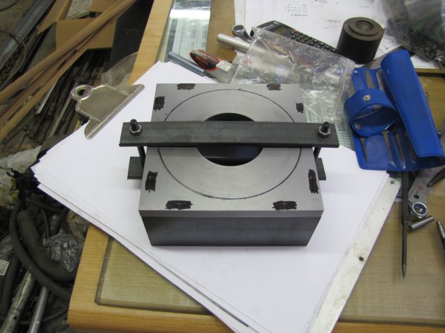
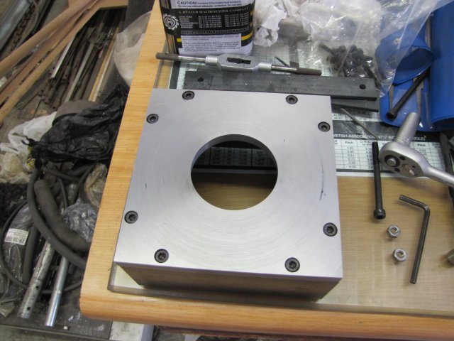
Then I sat down on the bar stool I keep handy (my "working table" is a bit high), and tapped each hole. The 5 mm clearance holes in the top plate are excellent tap guides to keep things square when starting with the first tap, so nothing fancy required as guide. Just manual work ;D. I'm due for a new set of M5 taps though; I could feel these starting to struggle, but they have tapped many tens of holes in the last two years... All bolted together:
Things went well didn't it ??? - Well NO - If you look carefully at the left hand hole in the top row in the picture, you'll just see the mark where the end mill wandered when the lot came loose on the mill table. Remember I said I didn't add the piece of paper below when clamping ? :wall: Fortunately I could recover; and another mark on the table to serve as a reminder... I think I can still hear some bad words echoing around the shop; fortunately Shrek was out of earshot!
With the base finally together, I started on the gear. A slightly oversize chunk of the phosphor bronze getting sawn off:
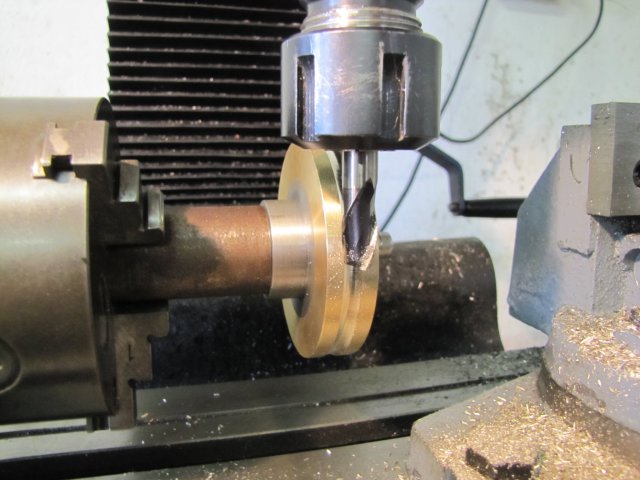
Then faced and bored in the 3-jaw:
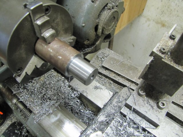
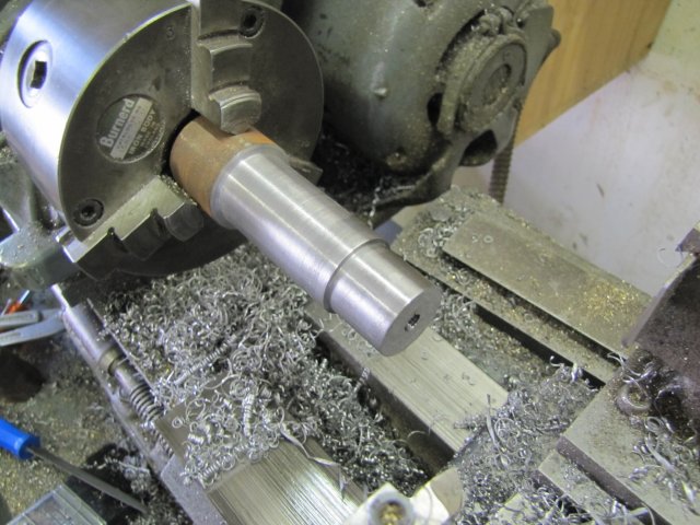
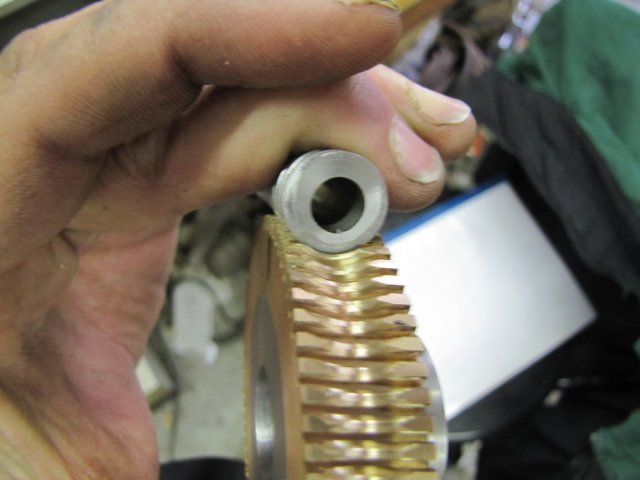
Next a section of the left-overs from that old big bolt was turned down for a press fit in the bore in the PB ring:
Then I sawed off the turned section of steel, and dumped it in my freezer on top of some ice for 10 minutes - it was nice and cold then ;D
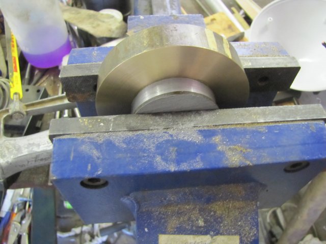
It pressed into the ring in the bench vise without too much effort, enough to give a good press fit, but not so much that the PB ring would crack:
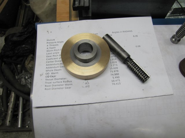
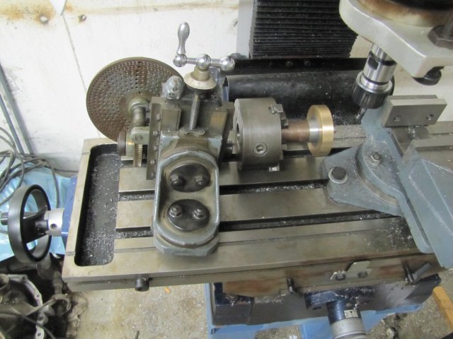
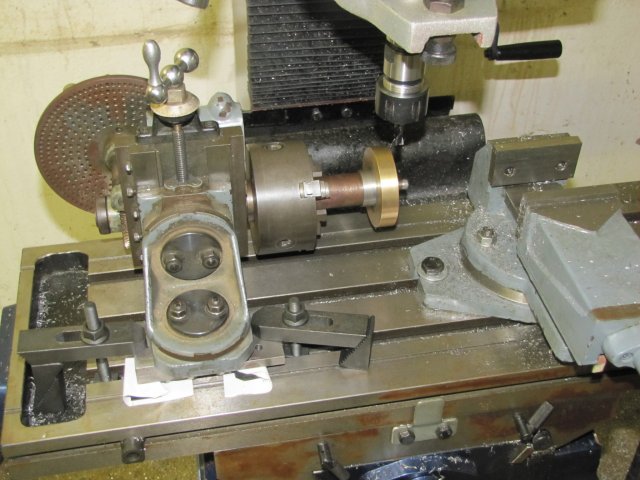
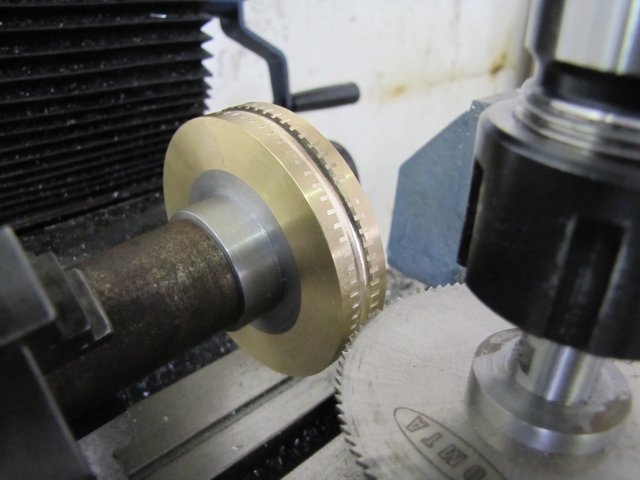
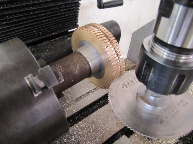
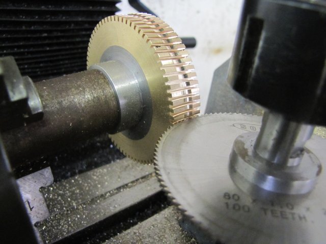
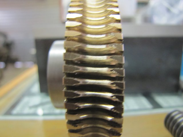
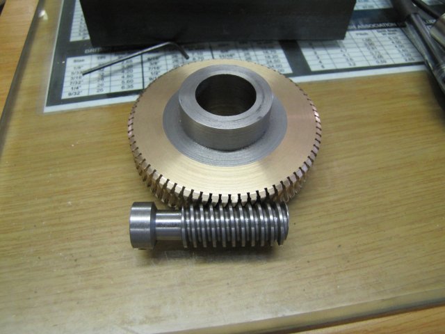
Some more turning, and I have the makings of a gear:
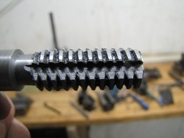
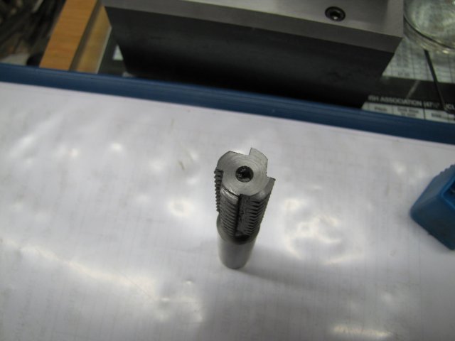
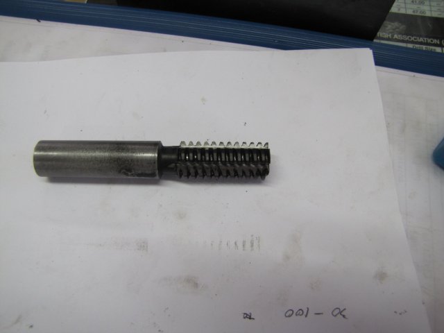
I need to double check some calculations now, and run through the needed steps in hobbing the gear in my mind, so updates might be a bit slow for the next couple of days. Think thrice - machine once...
Regards, Arnold

")