Building a 120mm rotary table

Home Model Engine Machinist Forum

Help Support Home Model Engine Machinist Forum:

This site may earn a commission from merchant affiliate links, including eBay, Amazon, and others.
Pre heating would help. Without looking I don't know what 2.5 converts to but running smaller rod on thick piece like that should still weld just fine and even a bit smoother then shown. In this case the best way to approach it would have been to do a triple pass. One right in the corner then followed by a bead on the lower side, or downhill side, and then a final pass on the upper side, hope that makes sense. "V"'ing out the corner was also a very good suggestion. Another way is to use a side to side movement or "C" movement and go very, very slow with a slightly long arc. Not sure if maybe your rod is designed for DC?

All I got to say I wish you was closer and I'd let your excellent milling abilities mill me a base and I would love to weld them together. I will probably tig weld mine. And thanks for the idea of building the base out of flat stock. I priced a 8" x 1/2" tube and they wanted $40/ft so I found a section of flat iron for $.30/lb
 
definitely preheat and weld from both sides bevel the outside pieces. that looks like half inch thick or as you would say 12 mm material. That is heavy stuff even for a real welder.
Not criticizing here I only have a little flux core wire feed myself so a lot of creativity to weld much .it does a fine job on 1/8 though.
I used to do tube and plate production welding 1 1/4 inch schedule 40 pipe welded to a 4" x 4" x 1/4 plate 300 - 500 a day it was fun up until the first 10,000. but after some practice i was told by our galvanizer that the customer said we had to have a robotic welder because no person could weld that fast and smooth ! Just call me R2D2. seriously though practice, practice and watch the puddle.
Tin
 
Bob, thank you. I did consider making the fillets - now I can kick my but for not doing it. Yes, it's a 220V single phase welder. I didn't know about the "slower flux" type rods; I'll have to investigate whether we have something similar here! I have a dedicated heavy duty extension cord for the welder, and I also replaced the puny short welding cables that came with it with longer and MUCH thicker cable, so that part should be OK :)

Philly, thanks; next time I have something on this scale, I'll try the pre-heating; that may be why the last weld came out the best as everything heated up a lot.

Thank you Hamstn. 2.5mm ~= 0.1". I did try the side-to-side; my hand's not steady enough :big: - and I still have problems trying to lie different beads as well. As to my milling skills, thank you for the compliment, but there is a lot of room for improvement there as well. I wouldn't trade the workbits though - and I don't mean that in a bad way; it leaves each of us to practice and improve on bits we need to improve ;D. And it's a pleasure if using the plates saves you a bit of money. It's not "my" idea though; I've seen it used for lots of different projects by many people ;)

Thanks Tin - and don't worry; I'm open to positive criticism (I think sometimes I'm my own worst critic!) It's 3/4" (10mm) plate. I hear you on the "repeated welds" - I've done a bit of welding (nowhere near your scale though :eek:) the last two weeks on a couple of frames from 1/8" (3mm) thick angle iron for a friend. On the last couple of frames I could weld everything up and by the time I did the last weld, I could just sit and wait for it to cool down and all the flux would crack off by itself. No chipping hammer required. That made the welds on the base all the more infuriating! But practice makes perfect ;D

Today was a bit quiet in the shop; I spent the morning helping a friend (the "frames" friend) to do some plumbing; soldering copper water pipe joints with the blow torch was a breeze :big:

I first faced off the one side of the welded base frame in the mill. I made a couple of quick clamping plates from more of the flat bar I used for the base - just saw off and drill an 11mm hole to allow some pivot clearance for a 10mm bolt , and sawed the heads off a couple of 10mm bolts to make shorter clamping studs than are in my clamping kit. The "new" clamping plates was needed as the clamping plates in my clamping kit is too thick for the slots I milled in the base. T-nuts and the clamping nuts came straight from the clamping kit. I cleaned the mill table VERY thoroughly before clamping down the piece on a bit of paper to prevent it slipping:
normal_IMG_1177.JPG

Sheesh - a lot of "clamping" in the above description; maybe I need to clamp down a bit ;D

Then I flipped it upside down to do the other side. Same process as above - clean and a new piece of paper. With the slots now higher above the table, I needed thicker spacers for the off-set ends for clamping... I settled on using some of the triangular step blocks from the clamping kit; a small one and larger one combined to provide the height. I couldn't use the flat bar clamp plates as-is on just one triangle block, as it is both a bit soft and too rounded on the ends to ensure a good grip on the step block. I don't recall ever seeing step blocks used in combination like this to , but it worked a treat ;D:
normal_IMG_1178.JPG


Today was a public holiday here in Namibia... I forgot about it... Completely... Imagine my surprise when I pitched up at the bolt & nut store this morning to buy some M5 cap screws for mounting the base plate to the frame ::) Not having those, I could not carry on with the base, so I started on the table.
The lump of cast iron centered near-enough on the 4-jaw. Neither of it's faces was particularly square, so I chose the "best" one to go into the chuck:
normal_IMG_1179.JPG


As I would be doing some "interrupted" cuts because the workpiece is not entirely round, and having a skew face, I center drilled it first, and added a revolving center. This was purely a precaution to make sure the workpiece stayed in the chuck if something came loose or jammed up. Some thoughts, a prayer and a thumb-suck made me select high back-gear speed on the lathe for cleaning it up on the circumference. This worked quite well, but my first cut was a bit on the shallow side (0.2mm), and quickly revealed a hard spot in the C.I. skin:
normal_IMG_1180.JPG


So I re-sharpened the toolbit (that hard spot just flattened it), and took a 0.5mm (0.040") cut to try and get under the hard spot. Instead of using the apron wheel for feeding, I locked the carriage nut, and used the lead screw handwheel for feeding; that gives a finer feed than the apron wheel. This cut came out much better:
normal_IMG_1182.JPG


Next I faced the front down as far as I could - this face was far out of square, and with a 0.01" ( 0.25mm) infeed per cut on the topslide, with the apron locked on the bed it took a couple of passes (8 in total ::)) to get here:
normal_IMG_1183.JPG


That's where I stopped for today; had to go to a BBQ with some friends, so I stole some time to write this up after getting back. Time for bed now :)

Regards, Arnold
 
Some more done today. I did not end up with much to show for the six hours I spent, but I'm taking things slow to avoid mistakes.

First up, I finished facing the piece - with tailstock removed. then I drilled a pilot hole through with a 7mm drill bit - pecking all the way to try and keep the hole as true as possible. The 7mm drill was just long enough for the job:
normal_IMG_1184.JPG


Then I drilled the pilot hole out to 13mm, and re-sharpened the tip of the carbide tipped boring bar that I broke earlier in the build, and bored the hole to 16mm dead. A test with some 16mm silver steel and I got a light push fit; precisely what I wanted. Then I bored the recess for the mounting flange with light face cuts from the inside the outside with a HSS toolbit that I ground to a good shape for this type of job on a previous occasion. This is part-way done:
normal_IMG_1185.JPG


Next I made the needed undercuts on the face. They came out a bit rough on the surface, as I used a threading tool to make them. Fortunately the running faces are nice and smooth - that's where it matters most for this project. Next up, it was the clamping groove. I did that with a parting tool and the lathe at its absolute lowest speed (back gear low speed). This was still slightly too fast, and I ran into problems with chatter. So I added the tailstock back for some additional support; fortunately my revolving center has a couple of different tips, and I could fit a bigger one to use with the 16mm center hole. This didn't help a lot though, so at the risk of chipping off the parting tool bit tip, I increased rate of infeed. Fortunately this worked and I soon got into the "groove" with nice chips coming off the parting tool and no chatter. A couple more passes with the parting tool, and I had the groove done:
normal_IMG_1186.JPG


I removed the 4-jaw from the lathe with the table-in-making still mounted on it, and set it aside. The 3-jaw went on, and I started on the main shaft. First off, cut a bit off the big bolt from the first photo in this thread:
normal_IMG_1187.JPG


Then gripped in the outside jaws of the 3-jaw on the non-threaded part of the bit of bolt, I lightly faced off the end and center drilled it for tailstock support. Then I rough-turned it down to get rid of the threads and then down to 26.5mm - this section will later be turned down to 25mm with some other steps and sizes included:
normal_IMG_1188.JPG

That's where I stopped for today; like I said - not much to show for 6 hours work! There is a bunch of chips though :big:
Fortunately we have a public holiday on Tuesday again, so I might get a bit further then.

Regards, Arnold
 
arnoldb said:
First up, I finished facing the piece - with tailstock removed.

Hi Arnold...

I didn't understand the above. Why did you remove the tailstock?

On a related question (and apologies if this is off topic)...do you (or others) remove the tailstock when it's not needed? Or just leave it mounted and slid out of the way? I tend to always take it off when I don't need it but then I'm left with 'where to put it'. My suspicion is that it just has to do with convenience...leave it on if it's not in the way.) Thanks.

I hope the BBQ was good. You didn't mention how it went. ;D I've yet to get a grill. I need it to become 'the complete man'...along with a riding lawn mower and a bowling ball. ;D
 
It looks like good progress, Arnold. You're working some pretty large pieces, there!

Some thoughts, a prayer and a thumb-suck made me select high back-gear speed

Yes, I think this is the way the professionals do it. ; )

Zee, in reply to your general question, I leave the tail stock on unless it's in the way, on my Atlas. On my little Taig, it's always in the way unless I'm using it.

Dean
 
zeeprogrammer said:
On a related question (and apologies if this is off topic)...do you (or others) remove the tailstock when it's not needed? Or just leave it mounted and slid out of the way? I tend to always take it off when I don't need it but then I'm left with 'where to put it'. My suspicion is that it just has to do with convenience...leave it on if it's not in the way.) Thanks.

Zee, The only time I remove the tailstock from the bed is when I need to get the saddle back that far. Normally a fixed steady also comes into play as well. Now back to Arnold's Rotary Table.

Best Regards
Bob
 
::) - I lost a LOT of post replies yesterday evening; I think all of them went to the old server. Having said that; it's not too bad; I'll revisit the W.I.P. section and repost as soon as I can. And many thanks to Rick and everybody who helped with the server move :bow:

Carl, thanks - the BBQ was great ;D. No Namibian is EVER without a grill :big: - but we have no use for bowling balls and ride-on lawnmowers ; only one bowling alley in the country I'm aware of, and small lawns (for those that do have them and can afford to pay for the precious water)
Machining questions are never O.T. ;D - and it was actually my bad; I should have said "removed tailstock support". In answer to your question though; my lathe's tailstock is on it nearly permanently; it only comes off for proper cleaning, and (very seldomly) if I need space. For the most part, if it's not in use, it is parked at the very end of the lathe bed. Like Dean said; it depends on your equipment. And like Bob commented; on the rare occasion where I needed to remove it to fit a workpiece, the fixed steady was always needed.

Dean, thank you ;D - I always thought the professionals pored over tables and calculated feeds and speeds in great detail :big:

Bob, thank you; I'll get back to it right away ;)


This afternoon I flipped the main shaft-in-making in the 3-jaw, and turned the flange section that mounts into the back of the table. The outside of the flange actually becomes a register to keep the shaft concentric with the table, and was turned as accurate as I could for a light push fit into the hole in the table. For some reason I got a poor surface finish; but cannot do anything about it now. This photo shows the part with the right hand section turned down to "register" size and the end already faced:
normal_IMG_1189.JPG


Next I used a right-hand knife tool to remove the excess metal and get the flange down to the needed 6mm thickness:
normal_IMG_1190.JPG


Action photo of drilling a 13mm hole part-way through the shaft - I love it when the swarf comes out in nice consistent curls like the ones lying below on the apron:
normal_IMG_1191.JPG


Boring the hole out to 16mm - after each pass I had to stop and remove the "rat's nest" that formed:
normal_IMG_1192.JPG


And done with the boring; the 16mm silver steel rod is a smooth fit in there - it acts like a piston and with the air trapped in the blind hole it pushes itself nearly right out again :) - I wish some of the pistons and cylinders I made so far was that close:
normal_IMG_1193.JPG


For the next bit I could have done with a rotary table ::)... I was too lazy to set up the dividing head in the lathe. So I decided to use the 3-jaw chuck as indexing device on the mill table. I clamped two blocks about 60 degrees (relative to the chuck outside diameter) to the mill table, and for the third side, I used a clamp and step block from the clamping kit. To mark index, I used the little square shown and just lined it up with its lower edge parallel to the T-slot, and used one of the chuck jaws sticking out slightly to get the first index position:
normal_IMG_1194.JPG


I centered the chuck using the table feeds and a bit of that 16mm silver steel in the drill chuck to go into the hole, zeroed the X handwheel and dialled in the 17.5mm offset I needed. Drilled the first hole, loosened the clamp, rotated the chuck against the fixed blocks to maintain position, and indexed with the little square on the same "side" of the next jaw. Clamp down the chuck again, drill & repeat for next hole... QED :):
normal_IMG_1195.JPG


Next the holes needed countersinking from the back side... My countersink bit is too big, and waaay to short to reach in there. A broken 8mm drill bit volunteered, and I carefully ground its end to a 90 degree angle with suitable cutting faces. That made countersinking easy, and the holes turned out quite well with no chatter:
normal_IMG_1197.JPG


The last step today, was to punch a witness mark into the flange and the back of the table; these I then "connected" with a scribed line - this will be used to make sure everything can be put back exactly the same at a later stage:
normal_IMG_1199.JPG


Progress thus far:
normal_IMG_1200.JPG


Pretty soon now I'll get into the more challenging bits of machining :) - I'm looking forward to that!

Regards, Arnold
 
Arnold,
Progress is being made here. It's looking more and more like a rotab!

I love it when the swarf comes out in nice consistent curls like the ones lying below on the apron:

I have swarf envy. Those chips look good enough to be bronzed and mounted on a pedestal :big: I wonder how many folks would see beauty in those curly chips? ???

Cheers,
Phil
 
Progressing VERY nicely, Arnold! :bow: :bow:

This is going to be a an attractive bit of kit.

Cheers, Joe
 
You're doing a fine job of it, Arnold.

Thm:

Dean
 
Sam, Phil, Joe and Dean - Thank you for your comments :)

:big:, Phil, the thought occurred to me to take some of the swarf and paint it in funky colours, shove it in a vase, and pass on to a girlfriend in lieu of flowers ;D. For the X - leave as-is & let it rust :big:. Seriously though; I'm happy to see the swarf like that as it means I'm putting on nice and consistent feeds - plus it's easier to clean ;)

Not much done today; but some none-the-less.

First I turned up a close-fitting transfer punch for the holes from some silver steel:
normal_IMG_1201.JPG

That was heated up to bright cherry / cooked carrots colour (For me its orange-red ;D) - hot enough to heat-treat, and dunked in some old motor oil I have for this purpose to harden it.

Then I used the punch to mark the table for the screw locations; simple; keep the alignment mark I made aligned; the punch is a close fit in the holes and stands upright by itself in each hole; and a good whack with a hammer on it and each center is marked:
normal_IMG_1202.JPG


I carefully centered and drilled each hole 4.2mm and 7mm deep on the mill with the chuck clamped to the table. After each hole, I used the drill chuck as a guide to run in the first tap from my M5 tap set. It only left a couple of threads on each hole before bottoming out, but enough to start the 2nd tap outside of the mill on the workbench. Each hole was run down with the second tap till it bottomed. Then the holes were run through with my modified version of an M5 plug tap - it had a pointed tip that I ground down while building "Fred" to really thread some holes to the bottom:
normal_IMG_1203.JPG


I purchased some Allen drive M5 countersink machine screws today. :wall: - when I measured everything initially, I only had some slotted head ones available, and the new ones' heads are bigger. I turned the excess off using the collet chuck in the lathe, but now the screws stand slightly too high. I don't want to face them off, as the hex sockets in them is not all that deep, so I'll make the countersinks on the flange a bit deeper later on if the heads interfere with the bearing. I want to use these screws, as they are high-tensile steel compared to the soft galvanized slot-heads I have. Today's final bits - screws in place and a "quicky" transfer punch:
normal_IMG_1205.JPG


Regards, Arnold
 
The project is looking great, Arnold. I'm following it closely.

A tip for using a transfer punch in an awkward situation such as this: Just use a couple light taps, just enough to start the divot. You will be less likely to move your parts alignment. You can came back later with the mating part removed and give it a proper mark with a center punch.

Also, a bit of white glue will help hold the parts aligned. White glue is sold in the US under the Elmer's brand name, maybe they have some in the crafts stores or apothecaries in Namibia. It's soft enough the pieces can be pulled apart and it's water soluble so it's easy to clean up.
 
Thanks for checking in and the advice Kevin ;D. I did actually re-punch the holes afterwards. I'll have a look into the "white glue" - we do get a water based white wood glue here (called Ponal, made by Henkel), but thats not water soluble once dried... Or are you talking about a glue more like the "paste" for paper etc. Never seen "Elmer's" glue - chance is if I saw it the first time without you mentioning it now, some of Mr Verburg's methods would become suspect :big:

Today's little bit...

I mounted the 4 jaw with the table/shaft assembly back on the lathe. I know my 3-jaw grips eccentric by about 2 thou - but dead parallel from the chuck to about 100mm away from it - on a 26mm workpiece, and when I tested the shaft on the whole lot as mounted now with a dial indicator, that's what I got. About 0.05mm eccentricity along the shaft's entire length, but it was parallel. The outside of the table part as mounted was still spot-on center. So I carefully turned down the shaft part to the needed 25mm for the bearing inner race; it was at 26.5mm so for a first cut I just took off an infeed of 20 thou (that takes _just) over 1mm - off the total diameter). Then I measured the piece to be sure - it was down 25.48mm. I honed the cutting bit in-place on the lathe; just a couple of light touch with the oilstone - then went down to just over size at 25.1mm. A last cut part-way for the last 0.1mm, and I stopped for a test with the bearing and it lightly pressed over - so I finished the cut:
normal_IMG_1206.JPG

Not super-smooth, but I'm happy with it.

And a final test; the bearing goes on all the way with a light push - just "some" pressure required ;D:
normal_IMG_1207.JPG


Next I turned the shaft down to 24mm up to a point 15mm away from the base of the table; the bearing is 17mm thick, and with the slight indentation in the table and the offset lip in the bearing mount hole in the base, that leaves me room for threading and run-out to the bottom of the bearing inner race. The 24mm section will be single-point threaded at 1mm pitch for the bearing pre-tensioner nut. I stopped short of the threading; that will take a while, and had better wait for the weekend.

Looking for something more to do, I decided on doing the holes to bolt the base top to the frame. I forgot to mark out the circle the table would run on on the base top plate, and being hit by a sudden sense of aesthetics, I needed to "see" a ring on the base top plate where the table would run. I pressed the bearing in the plate, and fit the whole lot over the shaft and used a permanent marker to mark the outline of the table on the plate:
normal_IMG_1208.JPG

:-[ OK - I'll admit; I just wanted to see and feel what it would be like to have the pieces together ;D

With the mentioned aesthetics in mind ::), I marked out and punched for the centers for the hold-down cap screws:
normal_IMG_1209.JPG

I stopped there, as while punching the holes, I found my concentration wandering to what I'll have for dinner, and also distracted by the swarfmagnets bashing around their stainless food bowls (must have had the same thoughts :big:)

Regards, Arnold
 
I had some more shop time today, and quite a bit of it was spent on something I particularly like - single point threading.

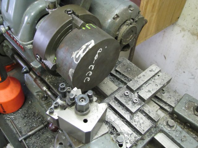
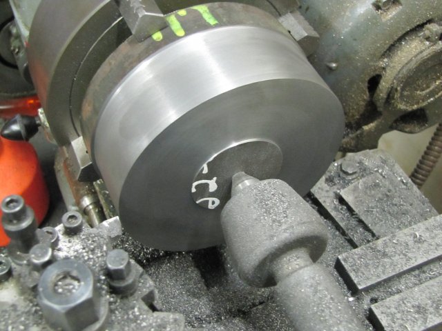
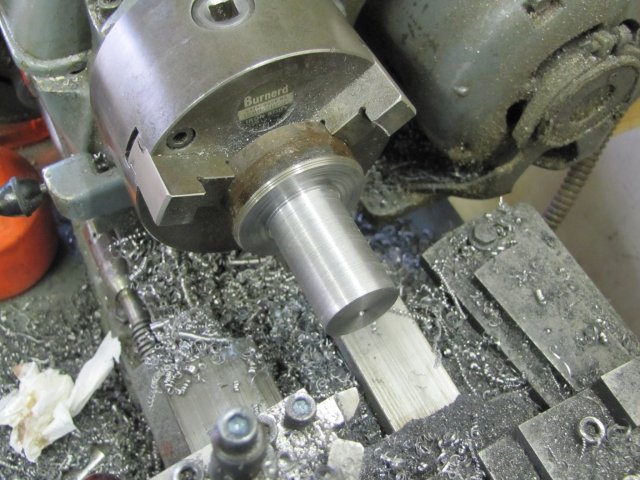
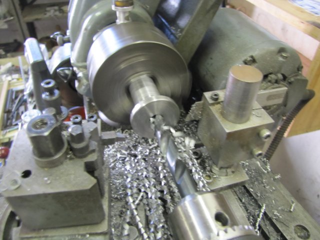
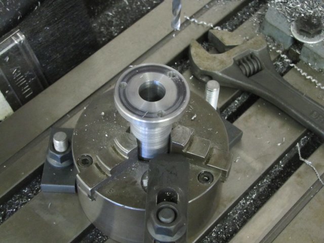
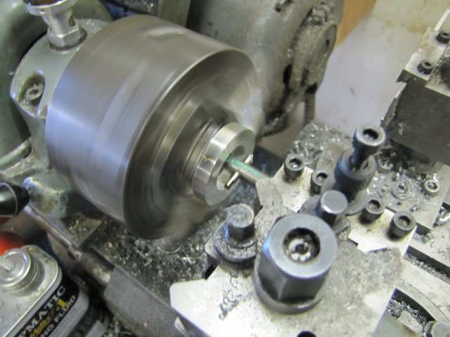
First thing, I decided to make the pre-load nut. I removed the 4-jaw chuck (with table in making et al) from the lathe and put back the 3-jaw with outside jaws. Some 50mm aluminium rod was then turned down to just under 40mm for just long enough to make an 8mm wide nut and allow parting off. Then I drilled it out to 19mm for the same depth (19 mm, as it is my biggest drill):
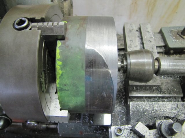
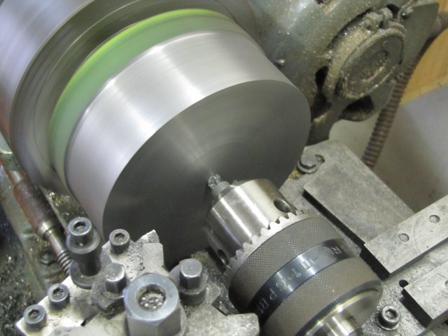
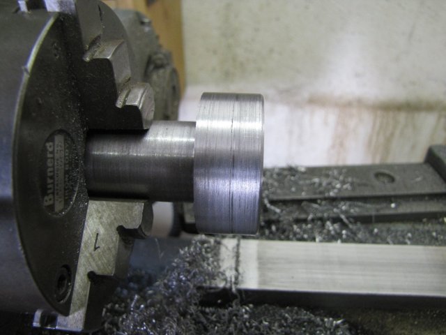
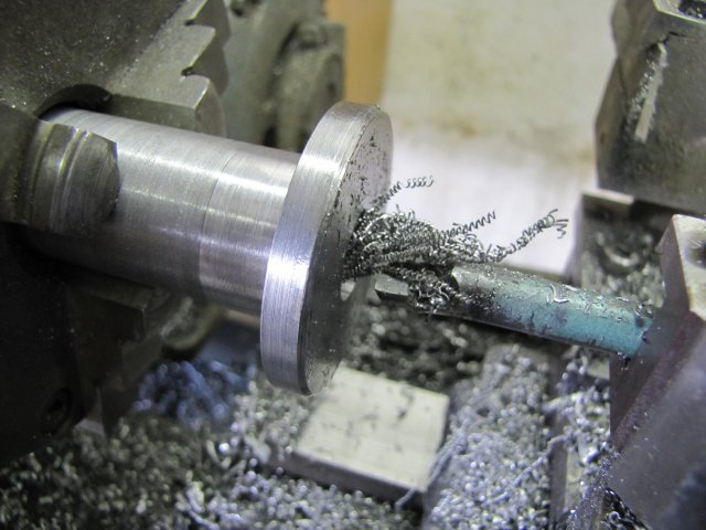
normal_IMG_1212.JPG


And parted off:
normal_IMG_1213.JPG

The white liquid is synthetic water soluble oil mixed with water. Normally I would have used methylated spirits on the aluminium, but I ran out. Sometime in the past, I did try this soluble oil on aluminium, but had less-than-satisfactory results on a 20:1 water:eek:il mixture as recommended for this oil. This is a "new" batch I made up just the other day, and through a fumble, this mix is more like 10:1 - and it worked a treat on the aluminium!

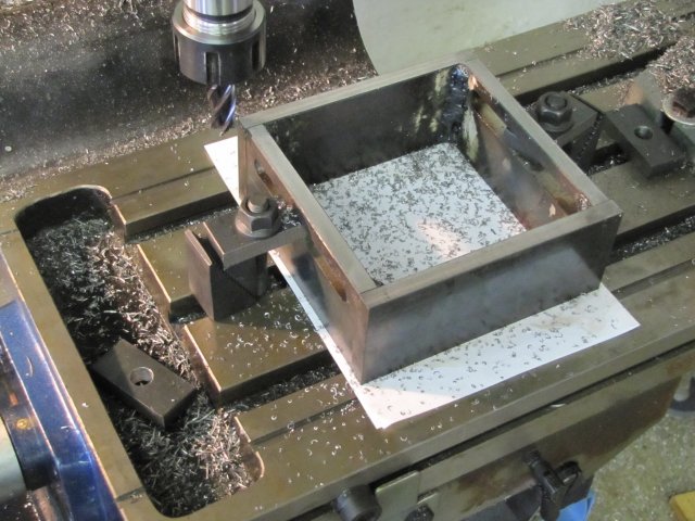
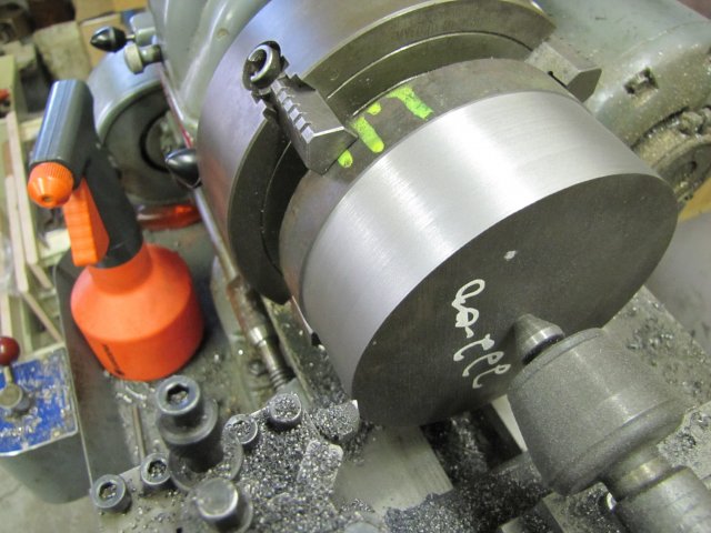
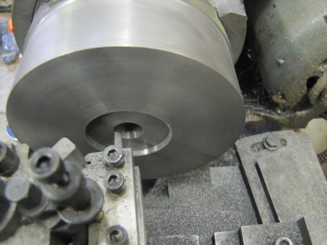
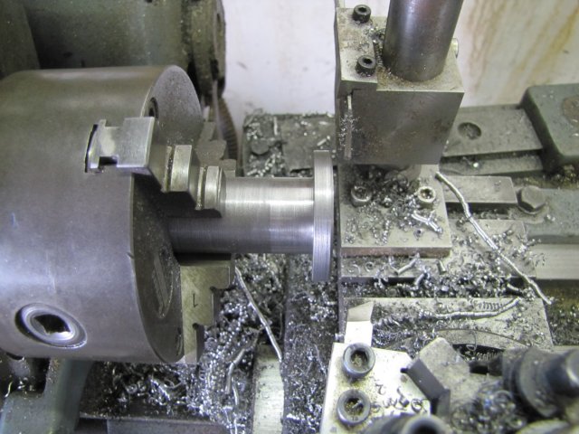
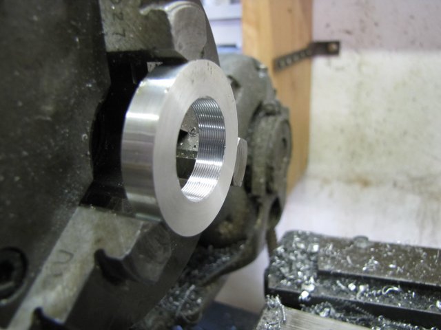
Then I changed back to inside jaws on the chuck, and chucked up the parted off bit of aluminium. It needed to be bored to inside diameter thread size next. I originally intended to thread the nut and shaft M24x1. The change wheels for turning a 40 tpi thread was still mounted (from making the Dremel chuck adapter for the mill here).
My thoughts went as follows: "I'm lazy to change the gear train. Would this much finer thread work ?... It would actually work well for the pre-tentioner nut - finer adjustment control and more than adequate grip. PLUS - I can use the thread dial indicator instead of reversing the lathe after each cut." Choice made ;D
For running a 40 tpi thread with a 60 degree angle, the thread depth would be 12.5 thou - roughly 0.32mm So the Inner diameter of the nut needed to be bored to 24 - (2 * 0.32) = 23.36mm. I bored it to that, and started setting up for threading.

I have a little multi-purpose boring bar I made out of an old carbide tipped tool shank that takes 4mm HSS inserts. I had a 60 degree threading "insert" already, so I put that in. Here I'm setting it to center height using a gauge I made as one of my first lathe tooling projects:
normal_IMG_1215.JPG

Note that the tip is upside-down. When I do internal threading, I do it with the tip upside down and cutting against the back of the workpiece. This allows me to do normal infeeding, and I can see what's happening in the cut. It's just easier for me ;D

Next I set the toolbit square using a fishtail gauge; the piece of paper is not to hide the swarf below for the camera shot, but to make it easier to see the tool tip relative to the "V" in the gauge. To set the angle like this would be tricky on the workpiece itself, so I used a length of silver steel chucked in the tailstock drill chuck to do it:
normal_IMG_1216.JPG


The toolbit approaching for a cut:
normal_IMG_1218.JPG

This looks like I'm running at high speed, but actually I was running at the lathes second lowest back-gear speed. I didn't try to take a photo while in the cut; had to mind the leadscrew disengagement lever then :)

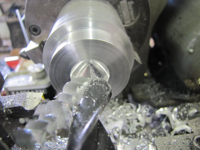
The finished threads after taking 2 thou cuts per pass, and about 2 passes on the same cross slide setting for the last two to work out the "spring" in the boring bar:
normal_IMG_1219.JPG


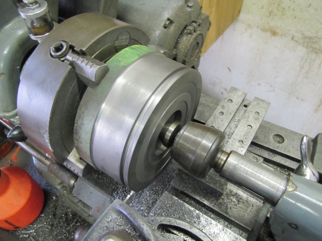
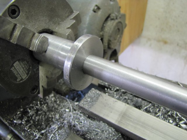
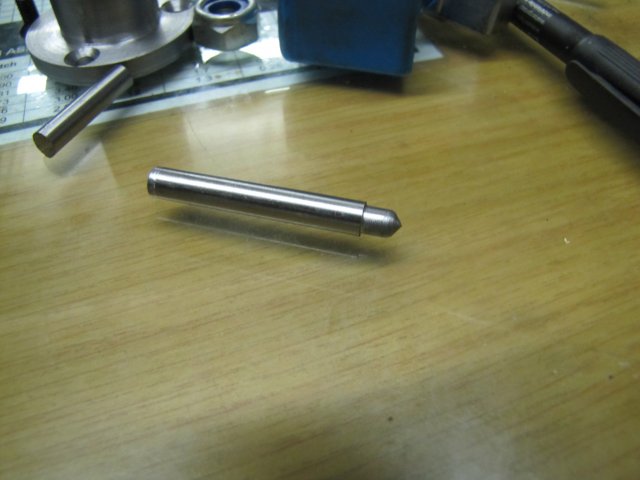
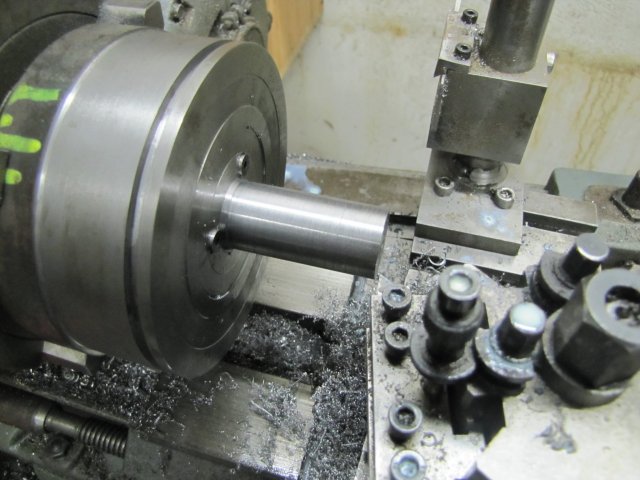
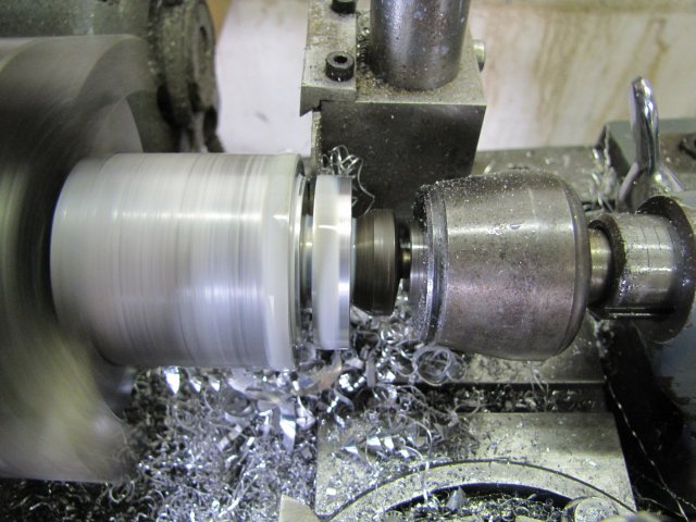
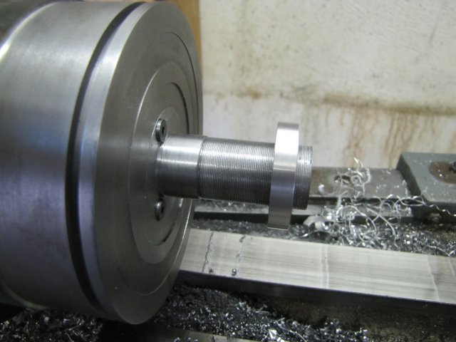
I then put the 4-jaw with contents back on the lathe, and turned the threads on the shaft. I was lazy, and just turned the insert bit in the boring bar upright again - that eliminated the need to set up a new toolbit - and turned the external thread on the shaft with it. The only thing I did before turning the thread, was to use the edge of a half-round file to make a thread run-out groove. When approaching final dimensions, I just tested with the nut for final fit. Here the thread is finished and the nut screwed on:
normal_IMG_1220.JPG

It looks a bit rough in the photo, but actually the nut spins about 1/3 of the length of the thread with a flick of the finger before it stops ;D

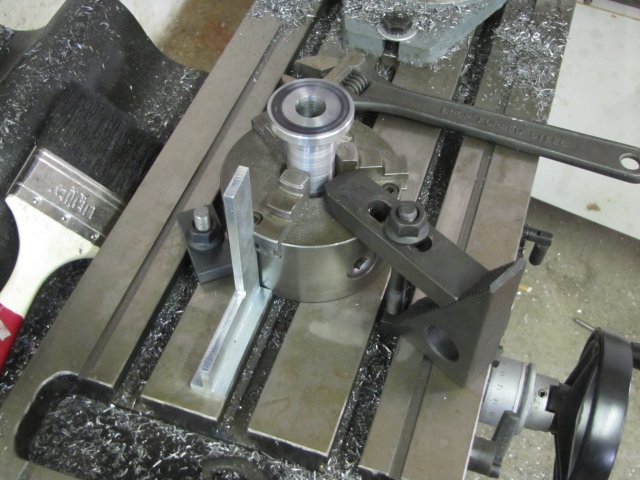
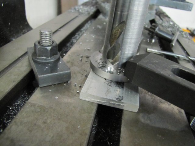
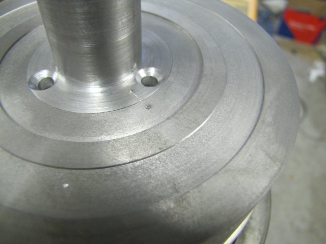
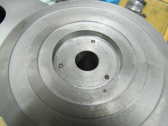
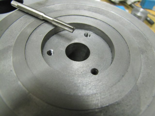
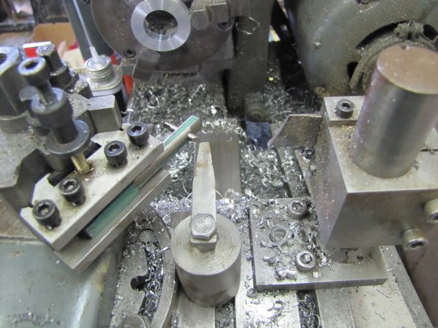
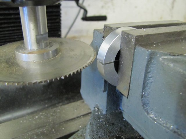
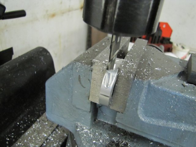
Next I did some more work on the nut in the mill. I want to be able to lock that nut in position when fitting the table together, so it needed some method of achieving this. I slit and counterbored it on one side with a 6mm center cutting slot mill to clear the head of an M3 cap screw, then center drilled the bottom of the counter bore, and ran a 2.5mm drill (that's for M3 tapping) right through, and then just drilled 3mm down to the slit for thread clearance. Then the 2.5mm section remaining below the slit was tapped M3 for as deep as my taps would go. I also milled two opposing flats on it for use when tightening it up. I didn't take photos of every step mentioned here; but here are two I did take:
normal_IMG_1222.JPG

normal_IMG_1223.JPG


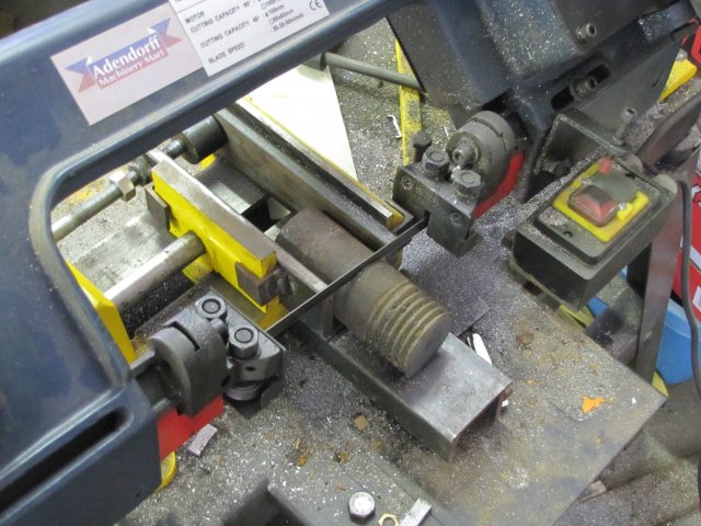
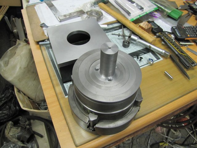
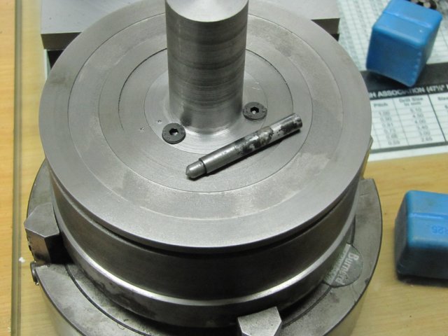
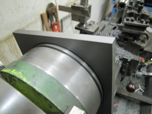
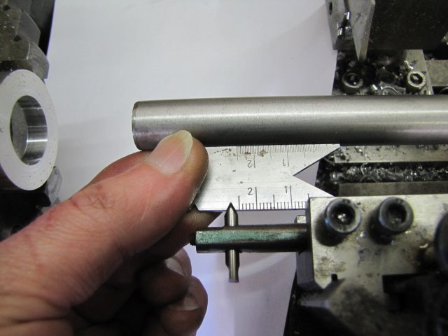
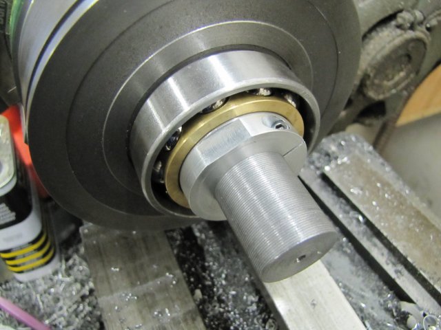
And finally - where I stopped for today, and how the nut will be used:
normal_IMG_1224.JPG


Regards, Arnold
 
It's looking great Arnold, and you're getting on with it pretty quick, too. I like the split locking collar you made here. Do you plan on lapping the mating surfaces of the table and body?

So, you like single point threading, then. Me too! Just seems fun to me, (as long as the threading dial doesn't come loose..).

Dean
 
Great documentation Arnold as usual. It's looking good. That threading job looks super :bow:

Cheers,
Phil
 
Is that a thrust bearing or is it a regular one? If it's a thrust one, it looks like it's mounted the wrong way around ???. Otherwise, nice job on the table. ;)
 

Latest posts

Back
Top