
You are using an out of date browser. It may not display this or other websites correctly.
You should upgrade or use an alternative browser.
You should upgrade or use an alternative browser.
Building a 120mm rotary table
- Thread starter arnoldb
- Start date


Help Support Home Model Engine Machinist Forum:
This site may earn a commission from merchant affiliate
links, including eBay, Amazon, and others.
arnoldb
Well-Known Member
- Joined
- Apr 8, 2009
- Messages
- 1,792
- Reaction score
- 12
Sam thanks ;D Our $ is pretty useless :big:
Thank you Dean ;D Yes - one bearing in each end, that is then preloaded from the shaft.
I've been eyeing Steve's boring head; in fact I have the plans sitting on my hard disk ;D I will most likely end up building it at a later stage - as you suggested with a 16mm shank and slightly bigger as my mill can handle bigger cutters. I'll also most likely adapt the feedscrew on it to work with a 0.5mm pitch thread; that will give nice metric settings for me with a 1mm full-size cut for every turn. But that's another project; RT first, then an engine, and most likely the boring head after that :big:
Thanks for checking in George") . I'm also still learning; the more you practice the easier it gets Thm: I don't have a full blown set of plans, as a lot of the work was done by the seat of the pants for some spares and material I had on hand. I'll try and put together some plans once done Most of the RT is loosely based on Dean's plans - here is a link to them and Dean's excellent build log. Have a look at the rest of Dean's builds as well; it's worth it! (Dean, I hope you don't mind)
. I'm also still learning; the more you practice the easier it gets Thm: I don't have a full blown set of plans, as a lot of the work was done by the seat of the pants for some spares and material I had on hand. I'll try and put together some plans once done Most of the RT is loosely based on Dean's plans - here is a link to them and Dean's excellent build log. Have a look at the rest of Dean's builds as well; it's worth it! (Dean, I hope you don't mind)
I started on the rest of the worm shaft assembly today. First a quick mark-out on a piece of 8mm silver steel:
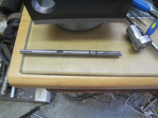
One end was turned down to 6mm for a length, and a space for thread-runout made with the rear parting tool, then I threaded the section left between the 6mm section and the run-out M8 - today I "cheated" and used a die instead of single-point turning the thread. Then I milled flats on the shaft; one on the 6mm section, another short one that will be the mounting spot for a collar, and the last flat for mounting the worm on:
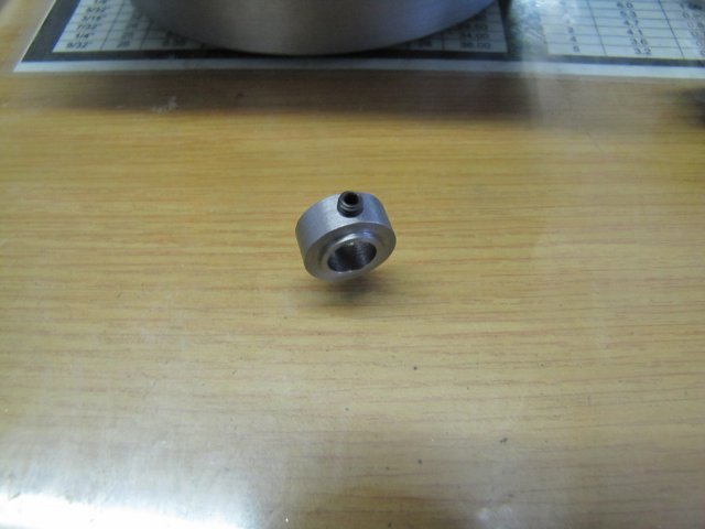
Next I made the collar I mentioned above from a scrap of HRS rod. The small ridge on it's side is so that it will only engage on the inner race of the ball bearing it will be pressing up against:
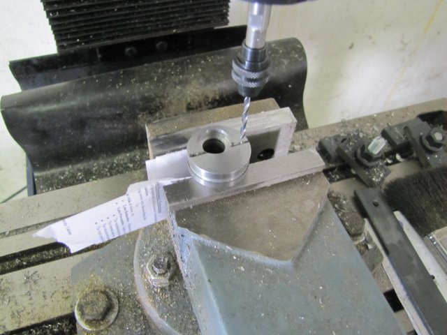
I drilled two 2.5mm holes (tap size for M3) into the eccentric to carry the Zero/Vernier scale plate:
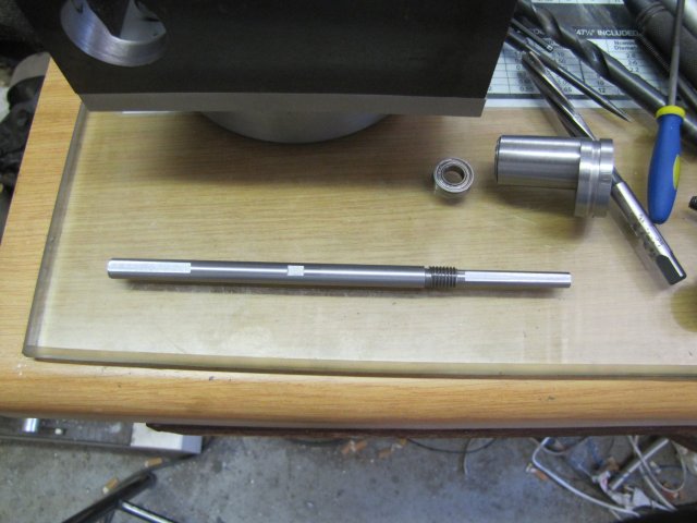
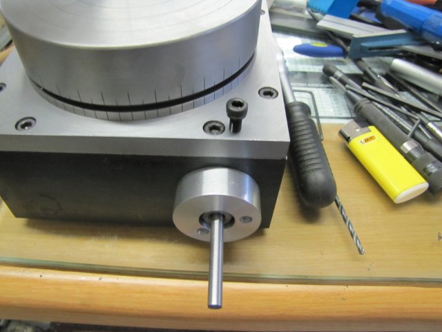
Then I cut a 12mm thick disc off some 40mm aluminium rod, faced it both sides and drilled a 16mm hole through it; this will become the Zero/Vernier plate. I then located it on the eccentric's bearing bore with a bit of 16mm rod and marked hole positions for drilling it's mounting holes by twirling the 2.5mm drill through the holes drilled in the eccentric. Then I drilled 3mm holes trough the plate on the marks, and counterbored the holes to 5.5mm to clear M3 cap screw heads. I also turned the end of a standard 8mm nut down to engage a bearing center like the collar I made earlier. Here is the collection of parts to make up the RT drive unit:
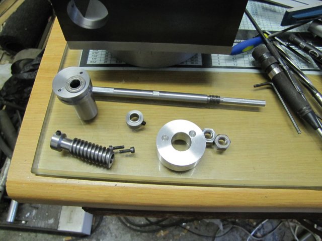
And all assembled:
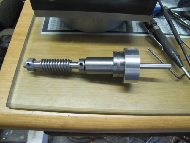
The turned down M8 nut and a corresponding lock nut for it is hidden in the zero plate.
Then I marked and drilled a 3.2mm hole from the top of the RT base through into the eccentric hole, and then opened it up part way down to 4.2mm and tapped M5. A short bit of 3.2mm bronze brazing rod to locate in the groove and a cap screw (for now) to tighten it down:
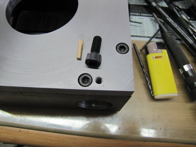
I struggled to get the cap screw shown above into the hole... Until I realised the hole is M5 and the screw M6 :-[ - An M5 cap screw went in easily :big:
A bottom view with everything assembled - I had to move the worm wheel over about 1mm towards the end of the main shaft to get perfect engagement with the worm:
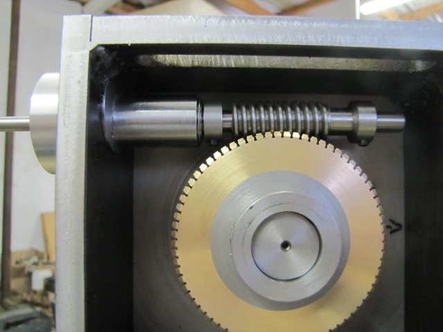
And an "operator's" view:
Does it work ? OOOH YES ;D. A light twist on the top screw, and the eccentric is loose to turn without coming out of the frame, and a twist on the vernier plate, and the worm engages with no perceptible backlash or disengages completely. And everything turns as smooth as silk and no lapping has been done yet ;D.
I think this project is about half-way done now... Fortunately we have a public holiday on Tuesday!
Regards, Arnold
Thank you Dean ;D Yes - one bearing in each end, that is then preloaded from the shaft.
I've been eyeing Steve's boring head; in fact I have the plans sitting on my hard disk ;D I will most likely end up building it at a later stage - as you suggested with a 16mm shank and slightly bigger as my mill can handle bigger cutters. I'll also most likely adapt the feedscrew on it to work with a 0.5mm pitch thread; that will give nice metric settings for me with a 1mm full-size cut for every turn. But that's another project; RT first, then an engine, and most likely the boring head after that :big:
Thanks for checking in George
. I'm also still learning; the more you practice the easier it gets Thm: I don't have a full blown set of plans, as a lot of the work was done by the seat of the pants for some spares and material I had on hand. I'll try and put together some plans once done Most of the RT is loosely based on Dean's plans - here is a link to them and Dean's excellent build log. Have a look at the rest of Dean's builds as well; it's worth it! (Dean, I hope you don't mind)I started on the rest of the worm shaft assembly today. First a quick mark-out on a piece of 8mm silver steel:
One end was turned down to 6mm for a length, and a space for thread-runout made with the rear parting tool, then I threaded the section left between the 6mm section and the run-out M8 - today I "cheated" and used a die instead of single-point turning the thread. Then I milled flats on the shaft; one on the 6mm section, another short one that will be the mounting spot for a collar, and the last flat for mounting the worm on:
Next I made the collar I mentioned above from a scrap of HRS rod. The small ridge on it's side is so that it will only engage on the inner race of the ball bearing it will be pressing up against:
I drilled two 2.5mm holes (tap size for M3) into the eccentric to carry the Zero/Vernier scale plate:
Then I cut a 12mm thick disc off some 40mm aluminium rod, faced it both sides and drilled a 16mm hole through it; this will become the Zero/Vernier plate. I then located it on the eccentric's bearing bore with a bit of 16mm rod and marked hole positions for drilling it's mounting holes by twirling the 2.5mm drill through the holes drilled in the eccentric. Then I drilled 3mm holes trough the plate on the marks, and counterbored the holes to 5.5mm to clear M3 cap screw heads. I also turned the end of a standard 8mm nut down to engage a bearing center like the collar I made earlier. Here is the collection of parts to make up the RT drive unit:
And all assembled:
The turned down M8 nut and a corresponding lock nut for it is hidden in the zero plate.
Then I marked and drilled a 3.2mm hole from the top of the RT base through into the eccentric hole, and then opened it up part way down to 4.2mm and tapped M5. A short bit of 3.2mm bronze brazing rod to locate in the groove and a cap screw (for now) to tighten it down:
I struggled to get the cap screw shown above into the hole... Until I realised the hole is M5 and the screw M6 :-[ - An M5 cap screw went in easily :big:
A bottom view with everything assembled - I had to move the worm wheel over about 1mm towards the end of the main shaft to get perfect engagement with the worm:
And an "operator's" view:
Does it work ? OOOH YES ;D. A light twist on the top screw, and the eccentric is loose to turn without coming out of the frame, and a twist on the vernier plate, and the worm engages with no perceptible backlash or disengages completely. And everything turns as smooth as silk and no lapping has been done yet ;D.
I think this project is about half-way done now... Fortunately we have a public holiday on Tuesday!
Regards, Arnold
Boy, Arnold, you really get down to business. That's a lot done at a single whack.
The whole spindle/worm/bearing/etc. assembly looks suspiciously like something that
came out of a machine shop. No surprise there! Very nice, indeed.
A small knurled brass finger nut would look nice in the hole for the eccentric lock.
Just a suggestion.
(Dean, I hope you don't mind)
Not at all, and thank you for the kind mention in your thread... again!
We all like our name up in lights, no matter what we say. ;D
Great thread, great build, great design work on your part, for sure!
BTW, this will make a fine video, when you've finished. We all like things that go 'round.
Dean
Deanofid said:BTW, this will make a fine video, when you've finished. We all like things that go 'round.[/size]
Indeed it would! I for one would be watching... after seeing this evolve I looked at my RT yesterday while using it thinking..... I wish YOU were home grown.....
Excellent project mate...
Rob
Arnold,
You do great work. :bow:
I understand that the eccentric is used to move the worm against the ring gear, what I don't understand is why not have the worm in a fixed position.
Boy, that last sentence confusses me and I wrote it. :big:
SAM
You do great work. :bow:
I understand that the eccentric is used to move the worm against the ring gear, what I don't understand is why not have the worm in a fixed position.
Boy, that last sentence confusses me and I wrote it. :big:
SAM
Hi Sam, I use mine in the free wheel position quite often, simply to move quickly to the next coordinate. Unlock, spin and relock. Otherwise its many many turns of the handle.
Sorry to jump in but I was onsite when you posted...
Sorry to jump in but I was onsite when you posted...
Arnold,
Not meaning to bust in on your thread..
Great work, as I said, hope to reach that level....
Dean, followed the link....and I got a bunch of info from your place.
Thanks for the link, and thanks for the detailed photos........great stuff.
George
Not meaning to bust in on your thread..
Great work, as I said, hope to reach that level....
Dean, followed the link....and I got a bunch of info from your place.
Thanks for the link, and thanks for the detailed photos........great stuff.
George
arnoldb
Well-Known Member
- Joined
- Apr 8, 2009
- Messages
- 1,792
- Reaction score
- 12
Dean, thank you ;D. I was thinking of a knurled finger nut as well; swarf has a habit of filling up cap screws. But more in the lines of a blackened HRS one :big: - I save my brass for engines I actually did take a short video clip of the hobbing in process, but it's pretty boring; maybe I must put a video together when done
Rob, thanks mate ;D Most likely I would not have built it myself if it was more convenient to buy one, but like Dean mentioned - it's an experience in itself; and maybe for the better; I'm using my own-built bits & bobs a lot, and it's always nice to pick something up and think "Hey, I built this and it's useful!" I must say though; from all the bits I built so far, my collet chuck is by far my favourite!
Thank you Sam ;D - Like Rob explained (thanks mate ;D), it's usable for "quick" indexing. I still need to finish off some holes on the table that will allow me to do just that - sort of like a spin indexer. Another use of this "feature" would be like where I had to make up the wood block to hob the worm wheel; it could be used in a pinch to just mount the chuck, loosen the worm, and hob away; a bit of abuse, but then again, having built it on the cheap myself, I wouldn't hesitate too much to do just that. It's intended as very much a working tool in my arsenal - I'm just practicing with the finishes for building better engines :big:
George, thanks ;D - I don't mind anybody posting; this is not "My" thread; it's just one that I happened to start. Everybody's welcome to chime in for the greater good ;D
Today I made the hand wheel and adjustable scale; quite a bit of shop time, but came out OK, and the only interruption I had was a friend pitching with some meat to stock the freezer - that was most welcome!
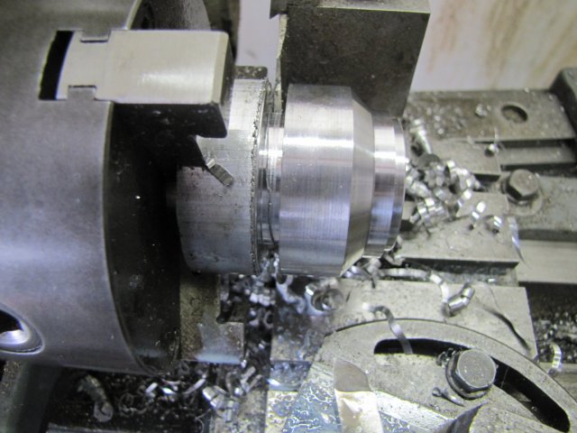
Started off with a hunk of aluminium:
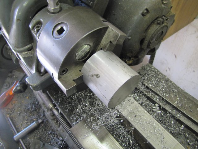
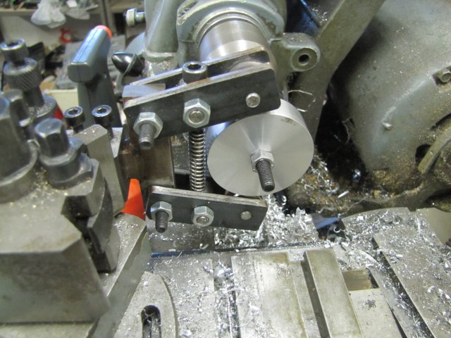
That I then turned down into the handwheel shape, with a boss on the front where the scale would locate on. Here it's all done and ready to part off:
Soon after starting the parting cut, I ran into chatter problems, but only on one section - the next photo shows the bit with chattering, while the rest of the groove is nice and smooth. I noticed while turning that there was a section in the aluminium rod that was harder or softer than the rest, and this is in that section:
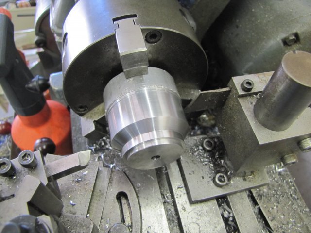
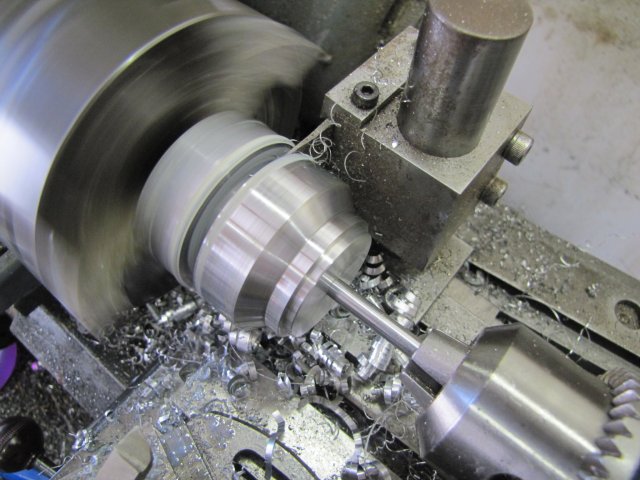
To overcome the problem, I slowed the lathe down to the next lower speed, and also started a "double parting" cut; this particular parting cut would be pretty deep - from about 50mm diameter down to 6mm and a double parting makes things a lot easier, even if wasting some material:
I didn't want the finish on the part ruined when it dropped off on breaking through on the parting cut, so I shoved a slightly smaller rod mounted in the tailstock chuck into the hole when things were getting close:
After parting; not very neat on the cut side:
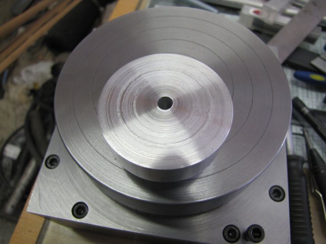
I cleaned up the untidy face by lightly gripping the part in the chuck with some soda can "protectors" and lightly facing off the offending bit. Then I mounted it on the RT for some final measurements. The face closest to the camera was the "bad" one above:
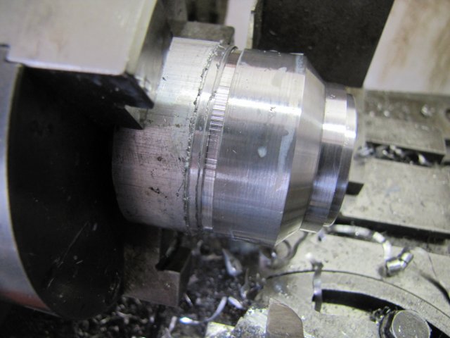
Next I started on the graduation wheel. Some 40mm aluminium rod with the end counter bored for a light push fit with the boss on the handwheel, and then just slightly cleaned up on the diameter, and with the parting tool a light groove turned to about 39mm diameter, so that I could knurl the projecting bit:
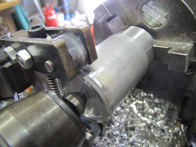
( :-[ I REALLY need to make a cleaner-looking and less sloppy knurling tool! )
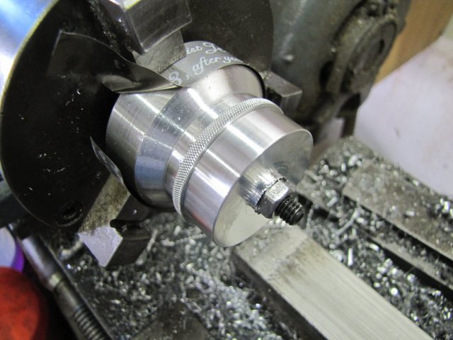
After that, I parted the graduation wheel on length from the parent stock. Then I mounted the handwheel and graduation wheel together with a cap screw, and mounted the lot in the 3-jaw, protecting the handwheel bit with some more soda can strip. My 3-jaw's outside teeth are still pretty accurate (less than 1/2 thou run-out on most diameters) - so good enough for here without resorting to the 4-jaw and centering. Next I turned the excess off the diameter and most of the face of the graduation wheel:
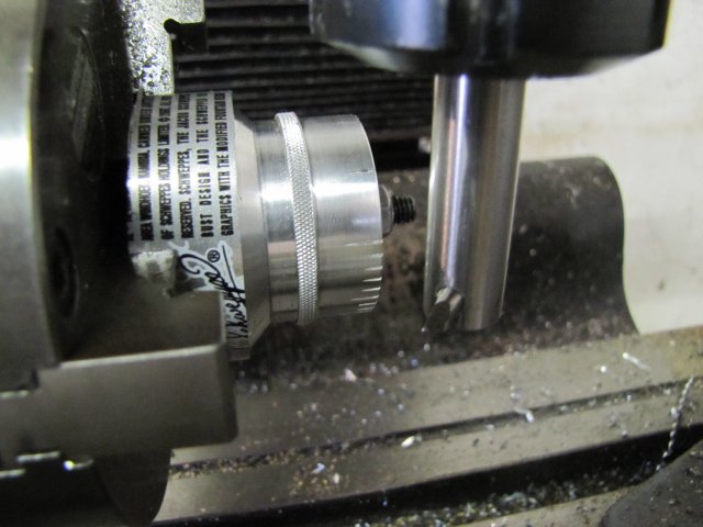
The dividing head was still set up in the mill, so I transferred chuck and all to that. A quick check, and I needed the dividing plate with the 45 hole circle. Mounted that, and then set to marking the graduations. The one and 1/2 degree marks were easy; my DH has a 60 tooth worm, so for the "one's" its "start at zero; graduate, 12 full turns, graduate; repeat". To get the halves, just crank six turns and repeat as for the tens. For the 0.1 degree marks, it was a bit more work; 1 1/5 turns per mark - but a LOT quicker than the 10s and 5s on the main table :big: - Here I took a break from counting and marking the 0.1s to take a photo - My mind was starting to wander so some timeout to restore focus after a careful note of current settings:
The handwheel still needed drilling and threading for a grub screw to mount it on the shaft. Here I'm using the old trick of using a flat plate (old feeler gauge plate) to find the center on the circumference to drill:
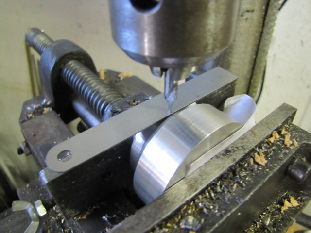
This method can be pretty accurate, but there are caveats...
In many descriptions of this method, a rule is used to do this. I don't like using a rule, as the engraved markings on a rule can have a negative effect. (anyway, good rules costs money )
One needs to check with the drill bit rotated to a couple of different angles and judge the "average" level.
A new spot on the plate should be selected for every test.
Don't move the workpiece while the drill press is under pressure; lift away the drill bit, move the workpiece or rotate the chuck and retry.
The smaller the diameter of the workpiece, the more accurate this method becomes (if you choose new bits on the plate for pressing down on, and don't use a rule where the engraved markings can cause a problem, and check with the chuck rotated a couple of times).
Gravity does have an influence if you're working with light pressures; try and have the plate balanced on the workpiece before starting.
Getting ready to knurl the handwheel - simply fit to the collet chuck with a cap screw from the back, and a nut pulling the wheel up to the chuck face. My biggest knurling job to date on a VERY "iffy" setup... This is at the extreme capacity of my rough knurling tool, and to boot, a knurling job wider than the knurling wheels... There's a LOT of sideways slop in that tool :-[ :
LOTS of coolant/lubrication from the synthetic soluble cutting oil squirt bottle (mostly to wash away any swarf build up) and the job was a good 'un; not perfect, but entirely acceptable for me for now.
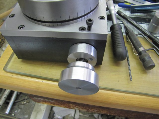
Next up I turned a shaft from 6mm silver steel, threaded M5 male one end and M5 female on the other (to accept an M5 cap screw), roughly turned, and finished with a file & emery a handle and drilled and counterbored it to take said cap screw and shaft, and parted it off 0.2mm shorter than the shaft. A bit of stiff spring salvaged from an old printer, shortened with the Dremel and ground down to length on the bench grinder, a couple of washers, a grub screw, and a short length of brazing rod all resulted in today's collection of parts:
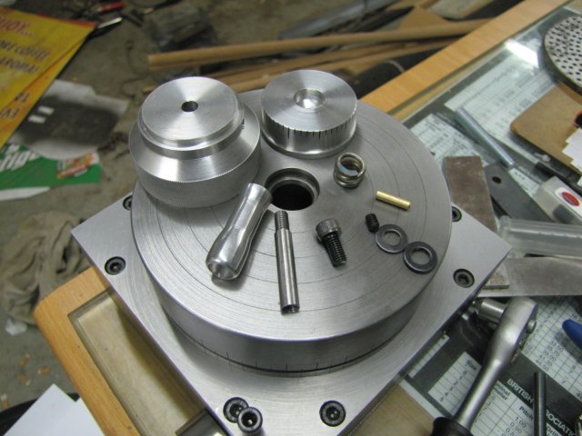
And duly assembled as a handwheel with zero-able scale:
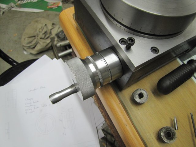
I'm quite happy; that lot came together rather well. The scale takes a "nice" amount of effort to adjust and does not slip on the handwheel at all.
Making the vernier scale on that zero collar is going to be a bit of a challenge, but I have some ideas around that I'll see what odds 'n ends I can finish during the week, but that particular job has to wait for the weekend.
Regards, Arnold
I actually did take a short video clip of the hobbing in process, but it's pretty boring; maybe I must put a video together when done Rob, thanks mate ;D Most likely I would not have built it myself if it was more convenient to buy one, but like Dean mentioned - it's an experience in itself; and maybe for the better; I'm using my own-built bits & bobs a lot, and it's always nice to pick something up and think "Hey, I built this and it's useful!" I must say though; from all the bits I built so far, my collet chuck is by far my favourite!
Thank you Sam ;D - Like Rob explained (thanks mate ;D), it's usable for "quick" indexing. I still need to finish off some holes on the table that will allow me to do just that - sort of like a spin indexer. Another use of this "feature" would be like where I had to make up the wood block to hob the worm wheel; it could be used in a pinch to just mount the chuck, loosen the worm, and hob away; a bit of abuse, but then again, having built it on the cheap myself, I wouldn't hesitate too much to do just that. It's intended as very much a working tool in my arsenal - I'm just practicing with the finishes for building better engines :big:
George, thanks ;D - I don't mind anybody posting; this is not "My" thread; it's just one that I happened to start. Everybody's welcome to chime in for the greater good ;D
Today I made the hand wheel and adjustable scale; quite a bit of shop time, but came out OK, and the only interruption I had was a friend pitching with some meat to stock the freezer - that was most welcome!
Started off with a hunk of aluminium:
That I then turned down into the handwheel shape, with a boss on the front where the scale would locate on. Here it's all done and ready to part off:
Soon after starting the parting cut, I ran into chatter problems, but only on one section - the next photo shows the bit with chattering, while the rest of the groove is nice and smooth. I noticed while turning that there was a section in the aluminium rod that was harder or softer than the rest, and this is in that section:
To overcome the problem, I slowed the lathe down to the next lower speed, and also started a "double parting" cut; this particular parting cut would be pretty deep - from about 50mm diameter down to 6mm and a double parting makes things a lot easier, even if wasting some material:
I didn't want the finish on the part ruined when it dropped off on breaking through on the parting cut, so I shoved a slightly smaller rod mounted in the tailstock chuck into the hole when things were getting close:
After parting; not very neat on the cut side:
I cleaned up the untidy face by lightly gripping the part in the chuck with some soda can "protectors" and lightly facing off the offending bit. Then I mounted it on the RT for some final measurements. The face closest to the camera was the "bad" one above:
Next I started on the graduation wheel. Some 40mm aluminium rod with the end counter bored for a light push fit with the boss on the handwheel, and then just slightly cleaned up on the diameter, and with the parting tool a light groove turned to about 39mm diameter, so that I could knurl the projecting bit:
( :-[ I REALLY need to make a cleaner-looking and less sloppy knurling tool! )
After that, I parted the graduation wheel on length from the parent stock. Then I mounted the handwheel and graduation wheel together with a cap screw, and mounted the lot in the 3-jaw, protecting the handwheel bit with some more soda can strip. My 3-jaw's outside teeth are still pretty accurate (less than 1/2 thou run-out on most diameters) - so good enough for here without resorting to the 4-jaw and centering. Next I turned the excess off the diameter and most of the face of the graduation wheel:
The dividing head was still set up in the mill, so I transferred chuck and all to that. A quick check, and I needed the dividing plate with the 45 hole circle. Mounted that, and then set to marking the graduations. The one and 1/2 degree marks were easy; my DH has a 60 tooth worm, so for the "one's" its "start at zero; graduate, 12 full turns, graduate; repeat". To get the halves, just crank six turns and repeat as for the tens. For the 0.1 degree marks, it was a bit more work; 1 1/5 turns per mark - but a LOT quicker than the 10s and 5s on the main table :big: - Here I took a break from counting and marking the 0.1s to take a photo - My mind was starting to wander so some timeout to restore focus after a careful note of current settings:
The handwheel still needed drilling and threading for a grub screw to mount it on the shaft. Here I'm using the old trick of using a flat plate (old feeler gauge plate) to find the center on the circumference to drill:
This method can be pretty accurate, but there are caveats...
In many descriptions of this method, a rule is used to do this. I don't like using a rule, as the engraved markings on a rule can have a negative effect. (anyway, good rules costs money
)One needs to check with the drill bit rotated to a couple of different angles and judge the "average" level.
A new spot on the plate should be selected for every test.
Don't move the workpiece while the drill press is under pressure; lift away the drill bit, move the workpiece or rotate the chuck and retry.
The smaller the diameter of the workpiece, the more accurate this method becomes (if you choose new bits on the plate for pressing down on, and don't use a rule where the engraved markings can cause a problem, and check with the chuck rotated a couple of times).
Gravity does have an influence if you're working with light pressures; try and have the plate balanced on the workpiece before starting.
Getting ready to knurl the handwheel - simply fit to the collet chuck with a cap screw from the back, and a nut pulling the wheel up to the chuck face. My biggest knurling job to date on a VERY "iffy" setup... This is at the extreme capacity of my rough knurling tool, and to boot, a knurling job wider than the knurling wheels... There's a LOT of sideways slop in that tool :-[ :
LOTS of coolant/lubrication from the synthetic soluble cutting oil squirt bottle (mostly to wash away any swarf build up) and the job was a good 'un; not perfect, but entirely acceptable for me for now.
Next up I turned a shaft from 6mm silver steel, threaded M5 male one end and M5 female on the other (to accept an M5 cap screw), roughly turned, and finished with a file & emery a handle and drilled and counterbored it to take said cap screw and shaft, and parted it off 0.2mm shorter than the shaft. A bit of stiff spring salvaged from an old printer, shortened with the Dremel and ground down to length on the bench grinder, a couple of washers, a grub screw, and a short length of brazing rod all resulted in today's collection of parts:
And duly assembled as a handwheel with zero-able scale:
I'm quite happy; that lot came together rather well. The scale takes a "nice" amount of effort to adjust and does not slip on the handwheel at all.
Making the vernier scale on that zero collar is going to be a bit of a challenge, but I have some ideas around that
I'll see what odds 'n ends I can finish during the week, but that particular job has to wait for the weekend.Regards, Arnold
wizardofwood
Active Member
- Joined
- Mar 25, 2010
- Messages
- 25
- Reaction score
- 0
Arnold
that is looking lekker hey.
A beautiful piece of work.
that is looking lekker hey.
A beautiful piece of work.
arnoldb
Well-Known Member
- Joined
- Apr 8, 2009
- Messages
- 1,792
- Reaction score
- 12
Thanks again Sam ;D - I like my sleep though :big:. Tonight I'm taking a break and attending to some other matters
Dean, thank you very much ;D. Its partly your fault though; you "pushed" me into it trying to improve my documentation :big: - Thank YOU!
;D Baie Dankie Wiz. .... "Lekker" :big: - one of those Afrikaans words that encompasses so many English ones in just a few letters ;D - yes it is lekker!
Kind regards, Arnold
arnoldb
Well-Known Member
- Joined
- Apr 8, 2009
- Messages
- 1,792
- Reaction score
- 12
Thanks very much Mike ;D - I saw your salvaged spares
I've been putting off further work on the table while waiting for a T-slot cutter I ordered 3 weeks ago, and to do some calculations for making the vernier markings.
The cutter arrived today, and the calculations are sorted out for the vernier markings. While picking up the cutter, I also added two circlip pliers to my arsenal - so that I can get around to adjusting my mill's spindle bearings which seems to be a bit loose...
Regards, Arnold
- Joined
- Jan 17, 2009
- Messages
- 887
- Reaction score
- 81
Real nice work Arnold
Good luck with the T sloter they can be tricky beasts to use, rough the slot out first with an end mill take it deeper than you will take the sloter if you try cutting across the full face of the sloter it will break, don't ask me how I know :
Stew
Good luck with the T sloter they can be tricky beasts to use, rough the slot out first with an end mill take it deeper than you will take the sloter if you try cutting across the full face of the sloter it will break, don't ask me how I know :
Stew
arnoldb
Well-Known Member
- Joined
- Apr 8, 2009
- Messages
- 1,792
- Reaction score
- 12
Thanks Stew ;D. I'll mill the slots slightly deeper at the bottom - I think about 0.25mm should do it.
Today I faffed around with the vernier collar and some number punches - and ended with a mixed bag of results...
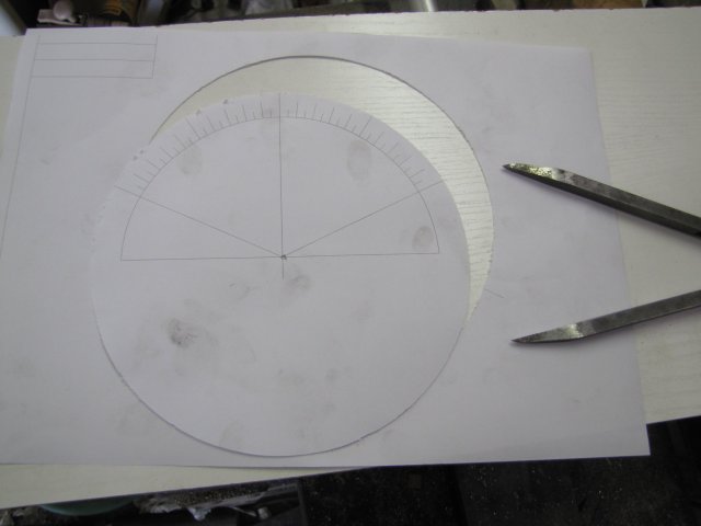
Having done the calculations for the vernier collar, I set out to make a template to mark it off it from. I cheated a bit, and instead of manually laying out the template with a pair of compasses, I did it with CAD and printed it. I know my old HP laserjet 6L prints very nice and accurate circles from QCAD, so no worries there.
Next I cut a "round" piece of plate from an old computer casing - here it is roughed out with some tin snips:
I just took it to the bench grinder to get it nice and round and without sharp edges - no finesse with a file, as this is a quick 'n dirty...
I used the compass to cut out the template from the printed page as well; I keep my compass fairly sharp, so it does cut paper albeit a bit crudely. At one point, I made a booboo and let the center slip, but not too much of a concern:
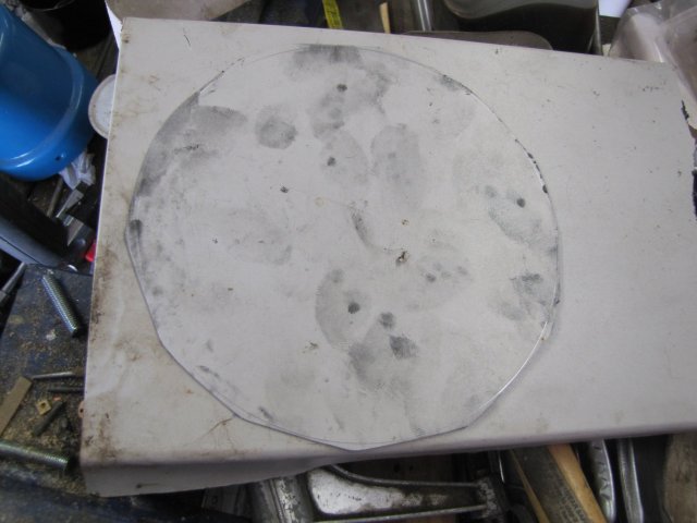
The paper template needed to be glued to the round plate... I didn't have any suitable glue on hand, so I used an ancient can of clear lacquer I've had for years (12 to be precise!) to spray a thick coating on the plate, and then stuck the paper template to it while the paint was still wet. Just for the heck of it, I ran another coat of lacquer over the top:
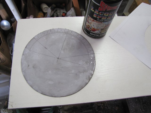
I didn't bother cleaning my hands so there are oily smudges all over the paper :-[
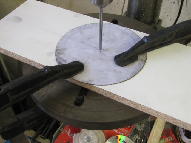
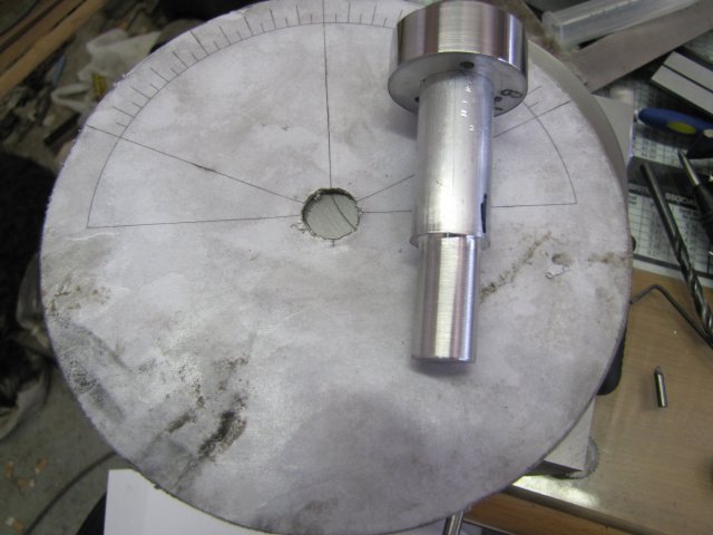
After leaving that lot in the sun for about 20 minutes to dry, I centered and clamped it on the drill press. Thoroughly. I needed to drill a 16mm hole through the center, and plate is a bugger on break-through:
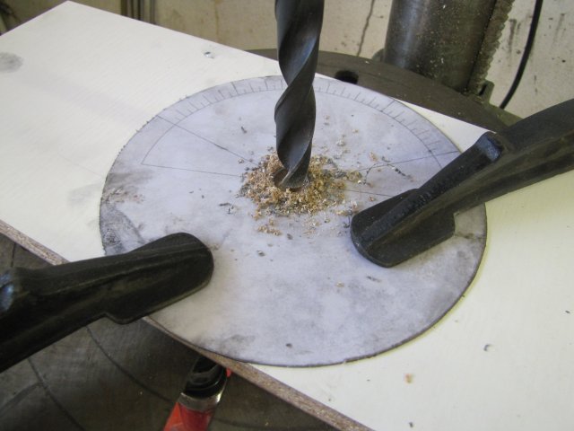
All drilled; no fuss or drama:
Next I turned a mandrel from some 20mm aluminium rod - to mount the vernier plate on one side, and a 16mm shank to grip in my collet chuck on the other side, with the template between the collet nose and the shoulder on the mandrel - here the vernier plate is already mounted on the mandrel:
I fully intended to take photos of how I clamped this lot together on the collet chuck... and promptly forgot to take any :-[. I mounted the collet chuck on the lathe, pushed the mandrel through the plate and into the collet in the chuck, and used the tailstock to press on the mandrel while tightening the collet closer. This kept the plate tight between the shoulder on the mandrel and the collet nose; I didn't want it to rotate later on.
Then I took the collet chuck with its contents off the lathe, and screwed it to the dividing head still mounted on the mill. For this job, the dividing head is useless for making the graduations (that's why all the fuss with a template) - but is useful as a handy mounting to make things go around.
Needing a way to index off the template, I taped my scriber securely to the magnetic base arm with some insulation tape, and set the lot up on the mill - with the scriber point very nearly, but not quite, touching the template:
Then I milled the markings; I made the template to conveniently show the lengths, so this was pretty much a no-brainer to do - except to get the scribe point as accurately on the line for each graduation as possible. I ended up with this:
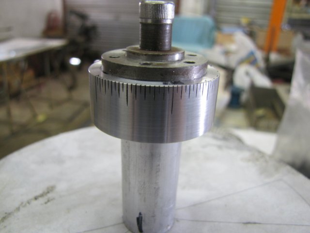
Quite proud of my achievement in making a vernier scale, I put it on the RT and tried it out....oh: oh: oh: :wall:
The scale is good - for working to 0.01 degrees. Those short 0.005 degree markings are completely useless... Had I stopped earlier this week and really thought things through, I would have realised it... The handwheel collar does not have 0.05 degree marks to align the vernier marks to in the 1/10th scale I made it at. To get the 0.005 vernier scale to work, I either have to put on the 0.05 marks on the handwheel collar, or I have to stretch the vernier makings through 18 divisions on the handwheel...
At that point I didn't know whether to kick my own butt, or to cry. Instead I ended up having a good laugh at myself for being too clever for my own good, and I'll leave things as is. The small half-marks on the vernier plate can serve as a future reminder that it's possible to do some nice work off a crude template and setup, that I need to think things through more clearly, and that sometimes I just need to laugh at myself. If the marks bother me in future, I'll make a new vernier plate. With my tests, I found that it would in any case be very difficult to index to 0.005 degrees using the 72 tooth gear wheel on this size. The 0.01 degree marks are good to use, and when I set out on this project, that was what I had in mind anyway.
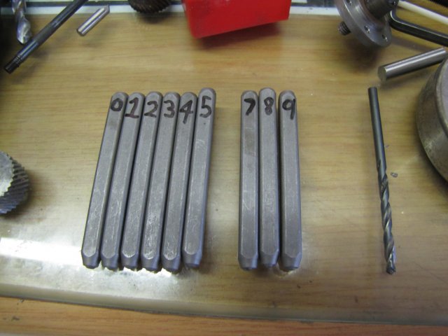
Next up, I marked my set of 3mm (1/8") number punches with a permanent marker. The numbers on the punches are oriented so that when the punch is held upright, and I can read the number, the punch is the correct way around to stamp the number properly:
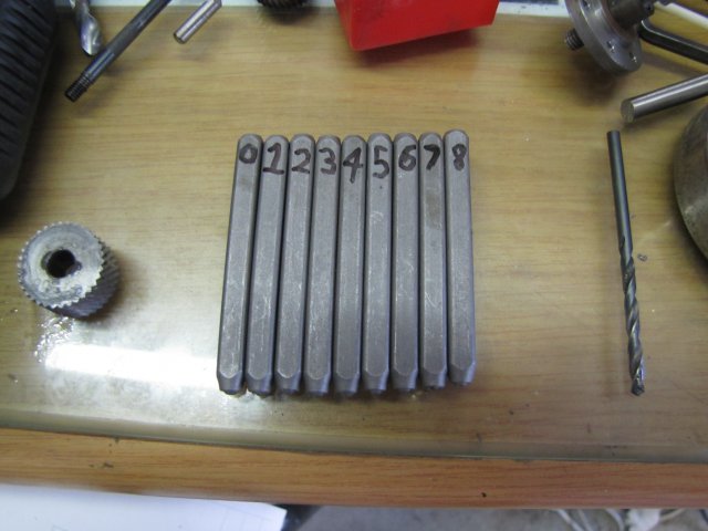
What, no 9 ??? - here it is; it's on the "other" side of the 6 punch:
And another crude jig to stamp the numbers. A slot milled through the face of some scrap HRS, and mounted on the magnetic base, mounted on my steel workbench serves as a punch guide. A small drill vise clamped to the table to hold down the workpiece, and I aligned the work with the end of the fixed jaw in the vise to set the depth:
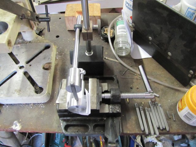
It worked sort of OK - Ideally I should have stamped the numbers on the workpieces while they were all still mounted in the lathe chucks, but I'd rather take some slight misalignment on the numbering than damage my chucks and so forth by hammering on work items in them.
Result of some stamping on the table itself:
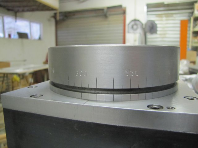
The two 3's on the 330 looks badly formed, but they are OK; I forgot to rub a dirty finger over them to fill up the recesses to improve contrast, and the lighting is playing havoc.
Some more of the numbering:
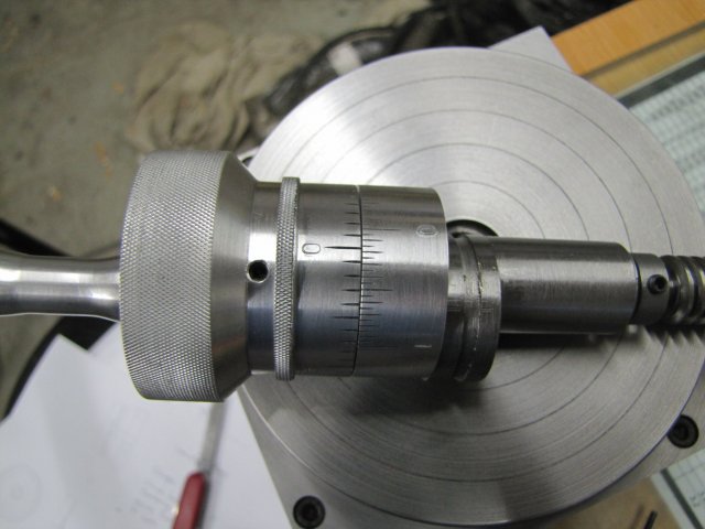
By no means perfect, but it will have to do for now.
I hope to get some more done tomorrow - thanks for reading along.
Regards, Arnold
Today I faffed around with the vernier collar and some number punches - and ended with a mixed bag of results...
Having done the calculations for the vernier collar, I set out to make a template to mark it off it from. I cheated a bit, and instead of manually laying out the template with a pair of compasses, I did it with CAD and printed it. I know my old HP laserjet 6L prints very nice and accurate circles from QCAD, so no worries there.
Next I cut a "round" piece of plate from an old computer casing - here it is roughed out with some tin snips:
I just took it to the bench grinder to get it nice and round and without sharp edges - no finesse with a file, as this is a quick 'n dirty...
I used the compass to cut out the template from the printed page as well; I keep my compass fairly sharp, so it does cut paper albeit a bit crudely. At one point, I made a booboo and let the center slip, but not too much of a concern:
The paper template needed to be glued to the round plate... I didn't have any suitable glue on hand, so I used an ancient can of clear lacquer I've had for years (12 to be precise!) to spray a thick coating on the plate, and then stuck the paper template to it while the paint was still wet. Just for the heck of it, I ran another coat of lacquer over the top:
I didn't bother cleaning my hands so there are oily smudges all over the paper :-[
After leaving that lot in the sun for about 20 minutes to dry, I centered and clamped it on the drill press. Thoroughly. I needed to drill a 16mm hole through the center, and plate is a bugger on break-through:
All drilled; no fuss or drama
:
Next I turned a mandrel from some 20mm aluminium rod - to mount the vernier plate on one side, and a 16mm shank to grip in my collet chuck on the other side, with the template between the collet nose and the shoulder on the mandrel - here the vernier plate is already mounted on the mandrel:
I fully intended to take photos of how I clamped this lot together on the collet chuck... and promptly forgot to take any :-[. I mounted the collet chuck on the lathe, pushed the mandrel through the plate and into the collet in the chuck, and used the tailstock to press on the mandrel while tightening the collet closer. This kept the plate tight between the shoulder on the mandrel and the collet nose; I didn't want it to rotate later on.
Then I took the collet chuck with its contents off the lathe, and screwed it to the dividing head still mounted on the mill. For this job, the dividing head is useless for making the graduations (that's why all the fuss with a template) - but is useful as a handy mounting to make things go around.
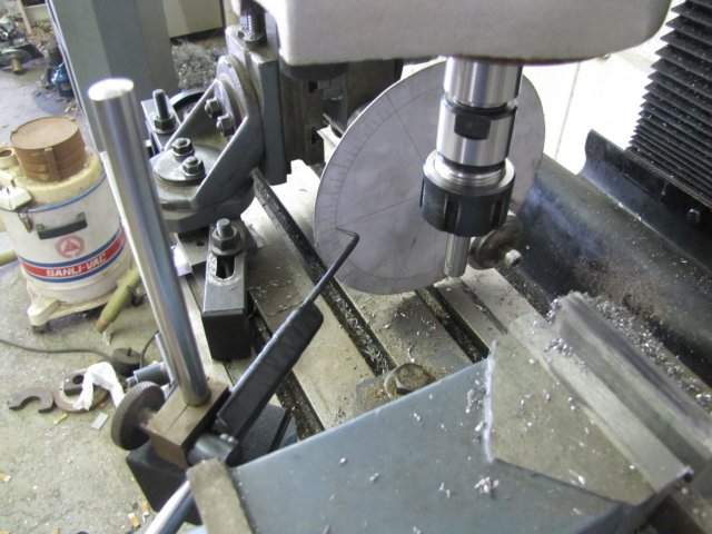
Needing a way to index off the template, I taped my scriber securely to the magnetic base arm with some insulation tape, and set the lot up on the mill - with the scriber point very nearly, but not quite, touching the template:
Then I milled the markings; I made the template to conveniently show the lengths, so this was pretty much a no-brainer to do - except to get the scribe point as accurately on the line for each graduation as possible. I ended up with this:
Quite proud of my achievement in making a vernier scale, I put it on the RT and tried it out....
oh: oh: oh: :wall:The scale is good - for working to 0.01 degrees. Those short 0.005 degree markings are completely useless... Had I stopped earlier this week and really thought things through, I would have realised it... The handwheel collar does not have 0.05 degree marks to align the vernier marks to in the 1/10th scale I made it at. To get the 0.005 vernier scale to work, I either have to put on the 0.05 marks on the handwheel collar, or I have to stretch the vernier makings through 18 divisions on the handwheel...
At that point I didn't know whether to kick my own butt, or to cry. Instead I ended up having a good laugh at myself for being too clever for my own good, and I'll leave things as is. The small half-marks on the vernier plate can serve as a future reminder that it's possible to do some nice work off a crude template and setup, that I need to think things through more clearly, and that sometimes I just need to laugh at myself. If the marks bother me in future, I'll make a new vernier plate. With my tests, I found that it would in any case be very difficult to index to 0.005 degrees using the 72 tooth gear wheel on this size. The 0.01 degree marks are good to use, and when I set out on this project, that was what I had in mind anyway.
Next up, I marked my set of 3mm (1/8") number punches with a permanent marker. The numbers on the punches are oriented so that when the punch is held upright, and I can read the number, the punch is the correct way around to stamp the number properly:
What, no 9 ??? - here it is; it's on the "other" side of the 6 punch
:
And another crude jig to stamp the numbers. A slot milled through the face of some scrap HRS, and mounted on the magnetic base, mounted on my steel workbench serves as a punch guide. A small drill vise clamped to the table to hold down the workpiece, and I aligned the work with the end of the fixed jaw in the vise to set the depth:
It worked sort of OK - Ideally I should have stamped the numbers on the workpieces while they were all still mounted in the lathe chucks, but I'd rather take some slight misalignment on the numbering than damage my chucks and so forth by hammering on work items in them.
Result of some stamping on the table itself:
The two 3's on the 330 looks badly formed, but they are OK; I forgot to rub a dirty finger over them to fill up the recesses to improve contrast, and the lighting is playing havoc.
Some more of the numbering:
By no means perfect, but it will have to do for now.
I hope to get some more done tomorrow - thanks for reading along.
Regards, Arnold
Yes, it IS looking very good. You show us some imagination in your line marking setup, too, Arnold.
Your numbers look good, to me.
I still don't have numerals on mine. I worry too much about double strikes, and fear of goofing up
permanent markings has turned me into a wimp. Someday I'll make a proper stamp punching guide,
and let my hammer do some talking.
You're really giving us a good show. Thanks!
Dean