Building a 120mm rotary table

Home Model Engine Machinist Forum

Help Support Home Model Engine Machinist Forum:

This site may earn a commission from merchant affiliate links, including eBay, Amazon, and others.
I'm a lazybones; normally I sleep till 9 or 10 am on a Sunday. This morning I awoke at 6 am with the same feeling of anticipation as a 6 year old on his birthday, and just could not get back to sleep

I've gotten this feeling more times since working in this hobby than I can count. It's what keeps us young, or at least thinking young ;D

Good job on the gear and many thanks for the tutorial on making it. :bow:

Cheers,
Phil
 
Rob, many thanks Mate ;D - now you can stop the stickpoke on the gear :big:

Thank you Stew ;D - You can uncross your fingers now ;) - I'm sure I'll use the same basic method in future!

Thanks Bob ;D ; I can be a wriggly one sometimes... This was like a chess game; thinking through the moves and scenarios were much harder than actually moving the pieces to get to the end result.

Dean thank you ;D - Yes; the cut is about 0.2mm to one side; the worm won't mind - but I do ::). In real life, I'm an "IT Administrator" - a very general term, as I look after the computer hardware/software/users/security/programming, HSE, building security etc. at the company I work for. I have a fairly broad technical background - originally qualified in electronics engineering, always interested in all forms of engineering, and done some interesting electronics security systems design, industrial process control systems and simulation software as a sideline to earn additional income. Before I bore everyone to death, I'll admit that I'm by nature very technically minded, and inherited this trait from both my father and grandfather. Just don't ask me who starred in _this_ and _that_ movie :big:

Thanks Phil ;D - and it's my pleasure to share - especially if my ramblings are useful to someone. I know what you mean; about the same feeling as finishing an engine and see it run for the first time. Now I have to get this RT finished and build an engine for a change!

Today's little bit is pretty boring. I milled three small flats on the gear flange and drilled and tapped in those for 4mm grub screws. Then I turned down the end of the shaft for a nice slide fit for the bore in the gear wheel, and milled flats on the turned down section for the grub screws to tighten up on:
normal_IMG_1277.JPG

With the dividing head still mounted on the mill this was a breeze. I'll make a dedicated mounting for it at some stage though; as the setup is far from rigid enough for serious work on steel - and I have quite a couple of future projects lined up that will require some gear-making.

Everything so far assembled for a look-see:
normal_IMG_1278.JPG

A bit of a revelation to me as well; the ideas I had for making the worm shaft adjustable just went down the drain; not enough clearance, so it's back to a bit of head scratching. And people wonder why I'm going bald... :big: At least it makes cleaning chips out of the hair easier ;D - life always have a positive side!

Regards, Arnold
 
hi Arnold, great job so far. I finally got some pictures and time to start my project and will start a thread soon.

I am at the point to add the worm screw also and I have been thinking on the idea you had to make it adjustable. I was waiting to see what you came up with first but the idea I had in the back of my head has been to build a bearing block for each end of the shaft to hold the bearings and mount them inside the table. I was then thinking about tapping the sides for bolts and slotting the holes in the bearing blocks for the adjustments. Hope that makes sense. The original design had two bearings on the crank end of the shaft but My shaft is almost long enough that I think it would be better with one on each end. I am also not sure the roller bearing I have will fit so if not I will move to brass bushings.

Keep up the good work, it's above my fit and finish but should still work the same in the end.
 
The assembly shot looks good, Arnold.
If that tooth thing is annoying, you could just face the gear until they are equal. I know what you mean about it. We want to get things juuust right. The functionality of the piece doesn't suffer, but the little man in our head won't leave us alone!

Thanks again for sharing. Looking forward to the next episode of "As The (R/T) World Turns".
; )

Dean
 
arnoldb said:
A bit of a revelation to me as well; the ideas I had for making the worm shaft adjustable just went down the drain; not enough clearance, so it's back to a bit of head scratching.

If I may jump in here, how about mounting the worm mount shaft in eccentric bushings/bearings to adjust your backlash? It shouldn't take up a lot of room and you can dial in what ever clearance you desire. You might have to shim the gear up or down but I think it could be doable.

Steve C.
 
Hi Arnold

Well, the "commercial ones" (vertex type) use a round material with an excentric bore. And this bore holds the worm gear. Maybe there is enough space to do it that way? Oh and the worm gear on the vertex rotarys is only supported on one side!

Florian
 
Thanks Dean - you're so right ;D

Hamstn, thanks ;D. Yes, your idea with slots for adjustment will work. I want to be able to completely disengage the worm easily for rapid indexing; something I need on a regular basis - for this, the slots won't work though.

Steve, you're most welcome to jump in any time you want ;D. Thanks; I initially thought about using an eccentric - then had other plans. It's definitely back to an eccentric again ;D

Florian, thank you; You've just provided the spark I needed - the shaft I have for the worm is more than rigid enough - and I now have an idea :idea: - I'll check tonight if it will work...

Regards, Arnold
 
Arnold

This is coming along very nicely. Your gear and worm look like something turned out by Rob Wilson... and that is a very good thing! :bow: :bow:

Cheers, Joe
 
Thanks Joe - much appreciated ;D - though there is quite a way for me to go to get to Rob's standards!

When I got home after work, I had a good look at what I have already, and an eccentric will work a treat. The gear height is adjustable - so that's not a problem; if it needs to move closer to the table top I can counter bore its face to clear the bearing pretension nut. Just some fine detail to finish off in my noggin - mostly related to the vernier scale I want on the assembly. As I'll need to turn an eccentric soon, it's time to get the table off the 4-jaw chuck. But this is no time to rush. I thought things through, and decided to graduate the table first; everything was set up ideally already; easy 72 divisions on the dividing head to mark 10 and 5 degree divisions on the table.

I haven't made a spindle lock for my mill yet, so I opted to cut the division markings rather than broach them like Dean did. Darn; all my suitable toolbits have square shanks... So first, a tool was needed. Some 10mm silver steel, a 4mm cross-drilled hole through at a slight angle (not needed here, but possibly in future) and drill & tap the end for a 4mm grub screw. A short length off the 4mm round HSS sticks I keep around; a bit of grinding, and the result:
normal_IMG_1279.JPG


On to the mill - with the cutter set dead on center. I fed Y till the cutter tip just touched against the side of the table, and then moved the workpiece away on X. Another 0.2mm feed on Y and then I started cutting the first 10 degree graduation. Just deep enough in on X till it looked good to me, then I set the mill table stop to stop there. Then it was turn the DH, feed X to the stop & back out; repeat till all the 10 degree marks were done:
normal_IMG_1281.JPG


And after repeating for the 5 degree marks on a shorter X feed:
normal_IMG_1284.JPG


Regards, Arnold
 
Always good things to see and stuff to learn from your threads Arnold.
Nice stuff!
 
arnoldb said:
though there is quite a way for me to go to get to Rob's standards!

Hi Arnold, aint that the truth!

Mate Ive been watching this fromt the beginning and Im darned impressed, you will use this tool to death once its finished, with the satisfaction of knowing, every time you pick it up that its YOURS.... a very very nice feeling.....

Excellent stuff, many od us dont appreciate how hard it is to get 'stuff' in a place like Namibia.... well done mate...

Rob T.. (as opposed to Rob W who is mentioned above)
 
Thanks very much Carl ;D

Rob, thanks mate ;D - I'm sure the RT will earn it's keep - I already have a couple of projects planned where it will be invaluable ;D

Well, no update on the project tonight; Had a couple of drinks with some business associates after work, so drink in and shop out.
I might dabble a bit with some CAD though ;D

Regards, Arnold
 
I finally got the table off the four jaw chuck this afternoon, as I could not see any further possible use for keeping it mounted.
First off was a trip to the band saw to get rid of the excess:
normal_IMG_1307.JPG


Bandsaws being the fairly rough machines that they are - and I've taken some pains to get mine as accurate as possible - the cut will inevitably shift slightly and not be perfectly square - especially in the vertical plane while cutting. I kept a careful look on the work, and when I detected too much of a deflection in cutting lines, I would stop the machine and turn the workpiece. I did this three times, as can be seen from the photo showing the table and the offcut:
normal_IMG_1310.JPG

The cut took about 15 minutes to complete - but the blade I have on the machine is not exactly new any more and is begging for replacement. The offcut will make a nice cast iron flywheel for a future project ;D

Next it was back to the 4-jaw with the table. I put bits of soda can on the radius of the chuck jaws to prevent marring of the graduation marks. Then I dialed in the table dead on center on the outside body with just a vibration coming off the needle of my best indicator when revolving the chuck. This step is crucial in the long term:
normal_IMG_1311.JPG


I then added a close fitting 16mm "test bar" in the hole I bored initially through the table center. For me this is a length of silver steel that I know is straight; no fancy test equipment in my shop (YET!). I tested run-out on this a good distance away from the table body. This was to make sure that the back of the table is at a precise 90 degree angle to the axis so that I could turn the face completely parallel with the back side:
normal_IMG_1312.JPG

Fortunately my old 4-jaw is pretty darn accurate on the faces of its jaws, so I did not have to resort to tricky measures to get things sorted; It was less than 0.005 mm out at the distance I measured, and that's fine with me in the environment I have.

I then faced the table repeatedly with very light cuts - just 2.5 thou infeed at a time; I didn't want a sudden heavy cut on the irregular bandsawed surface to knock things out of kilter! Then I bored the center hole out to 20mm diameter to a depth of 5mm - this will become the register for my lathe chuck mounting plate - and chamfered the register hole and internal 16mm step left at a 30 degree angle. This is for easy location of mounting the chuck plate in future, as well as for easy centering of the RT on the mill table with a bit of 16mm rod clamped in the collet chuck. As a final step, I used a sharp-pointed threading bit to turn light alignment rings on the face 10mm apart from each other.
The assembled lot is starting to look like an RT - with the exception of the glaring blunder on the bottom right hand cap screw counterbore that caused so much heat in the shop a while ago ;D:
normal_IMG_1319.JPG


Regards, Arnold
 
Arnold,

You are building a $1000 rotary table. It looks fantastic and I'm keeping notes on the ways you are insuring accuracy in the finished product.

SAM
 
Awesome work and quality. Really impressive.
Don't worry about that 'blunder'...it makes it yours.
Unique.
People will know it was made by a craftsman...and not a business.
 
That is some fine work you have there Arnold (except for that one counterbore ;D) That would be a good spot for one of those metal ID tags, you know, to cover up the scar stickpoke I'm impressed with how you did the hash mark 'etching' NICE Thm:


BC1
Jim
 
Really some great quality work here, Arnold. An enjoyable thread, and hopefully it's giving folks
some good ideas. This is one of those shop projects that pays off in experience as well as tooling.

Extra good!

Dean

Oh yeah.. Position the doink toward the back when you put in your worm shaft. It won't bother
you so much!
; )
 
Sam, Thanks ;D - $1000, well, then I'm not doing too bad then :big:; that's just slightly more than what a 6" import table would cost me delivered here in Windhoek! (N$6700 - and the exchange rate is currently N$7.60 to 1 US$). Besides the money thing; it's a lot of fun!

Zee, thank you ;D - If When the table is in use, I'm sure I'll forget... Except when I look at it... Oh well, one to remind me of the "Wall of learning" ;D. As to craftsman - well no, "aspiring craftsman" - yes :big:

Thank you Jim ;D - the hash marking method just seemed the simplest solution to me. Your ID tag idea gave me an idea; how about a little brass gravestone mounted on top of it - engraved "Below lies Error - Rust in piece" ::)

Dean, Thank you ;D. If this build log gives people good ideas, then I get triple satisfaction from it - experience, tooling and helping someone! :big: When I did today's work I made sure doink is in the back!

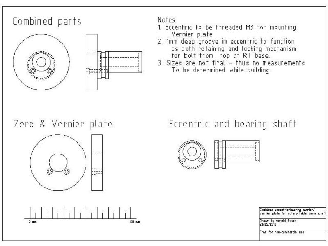
I've been doing some CAD work in the eccentric to try and sort out what I would do. Finally, I arrived at the following:
normal_RotaryEccentric.jpeg

An eccentric/bearing carrier/vernier plate carrier combination thingumyjig that would give me the features I want. You can download a dxf CAD version here

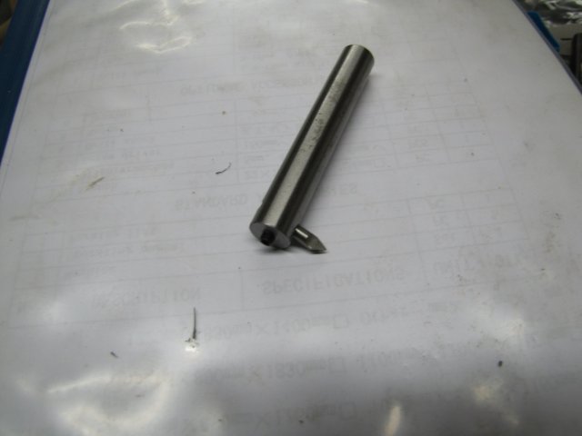
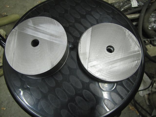
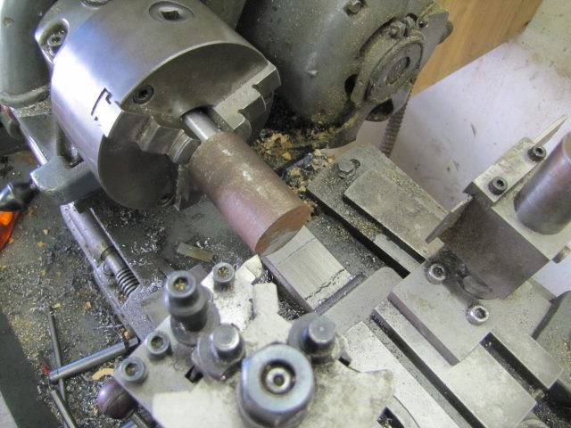
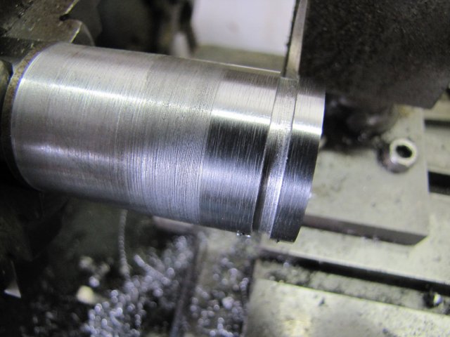
I set off making the eccentric from some HRS rod (in fact, the left over bit that I had the gear wheel mounted on):
normal_IMG_1322.JPG


Some clean-up and a groove parted in as per plan. Not the best of finishes!:
normal_IMG_1323.JPG


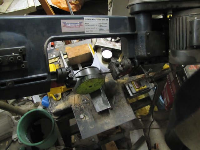
Then I bandsawed the excess off, and mounted the workpiece 5mm off-center in the 4-jaw. Then I turned down the body (not really needed, but makes things easier in future) and drilled a hole through and bored a pocket for mounting a bearing:
normal_IMG_1324.JPG

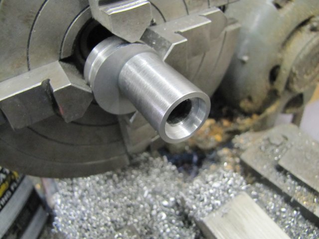
With the body turned down, it was easy to mount the three-jaw chuck and bore the opposite bearing's pocket. If the body wasn't turned down, this would have meant using the 4-jaw to bore the pocket. It might have been quicker to do this... I thought I took a photo of the finished eccentric, but while downloading the photos from the camera to my PC I saw that I thought wrong :-[

I took measurements from the thus far assembled RT to determine the "center" hole position for the worm shaft "as if I was not going to use an eccentric". Then I added in the eccentric factor and the rotational position I wanted it to occupy for "worm engaged" - which should be the same as not using an eccentric. Some trigonometry calculations and I had the center coordinates for drilling and boring the hole in the RT base for the eccentric.
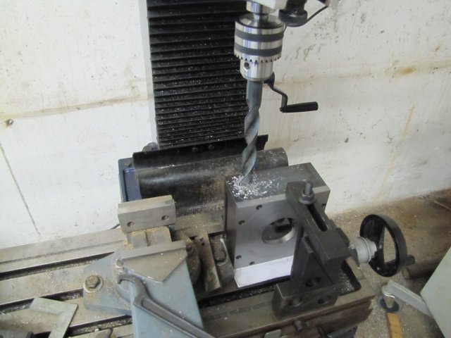
I marked that, and set up the base on the mill for drilling and boring. After center drilling, and drilling a 7mm hole, I switched to my biggest drill; a 19mm one:
normal_IMG_1325.JPG

I've used this drill bit in the lathe quite a bit, and the old Myford copes with it at medium back gear speed with some complaining. My 16mm drill press does not; it's lowest speed is too high. The mill utterly surprised me. On it's highest low range speed, it just turned that "little" drill bit - no complaints whatsoever - and at a good feed rate as well!

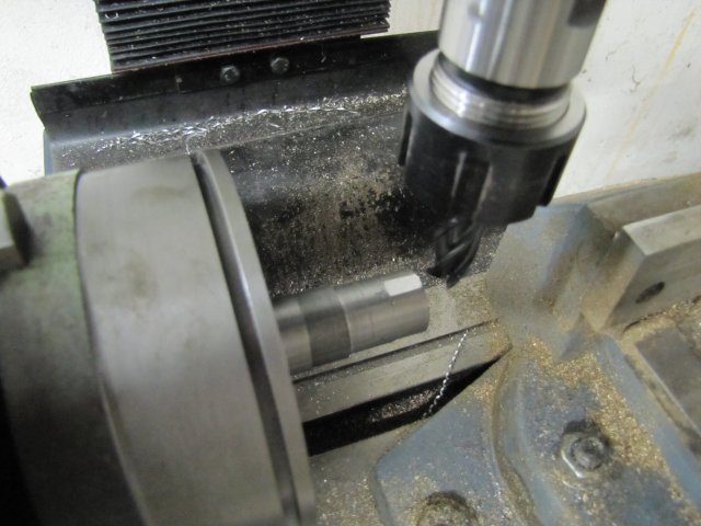
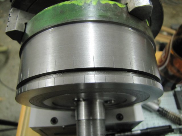
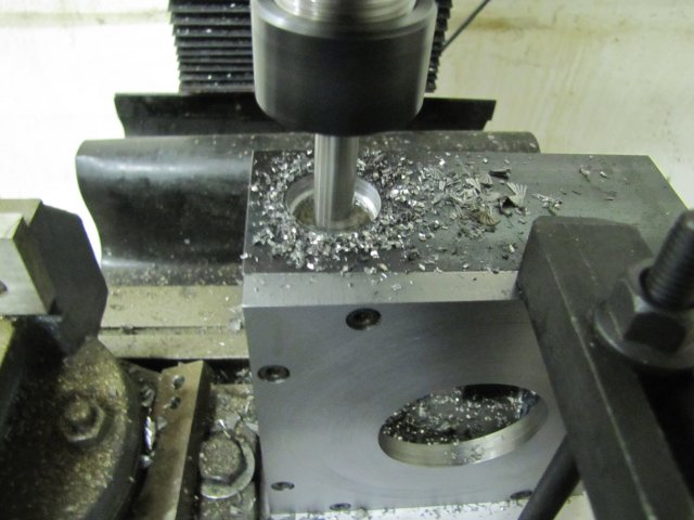
I still need to make or buy a boring head for the mill. The 19mm hole I had needed to be bored out to 30mm for the eccentric. I used the boring bar I made for the degree markings and another bit of HSS ground to what I thought would be appropriate angles to bore the hole out. Another surprise! I could go at a good depth of cut - in this photo I'm taking 2mm out of the diameter of the hole (1mm DOC) at a slow but steady down-feed:
normal_IMG_1326.JPG

The hole was bored to a good sliding fit for the eccentric.

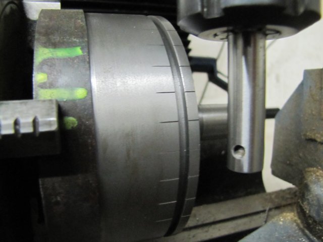
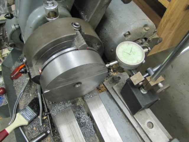
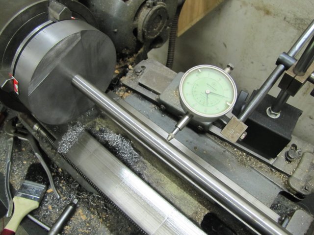
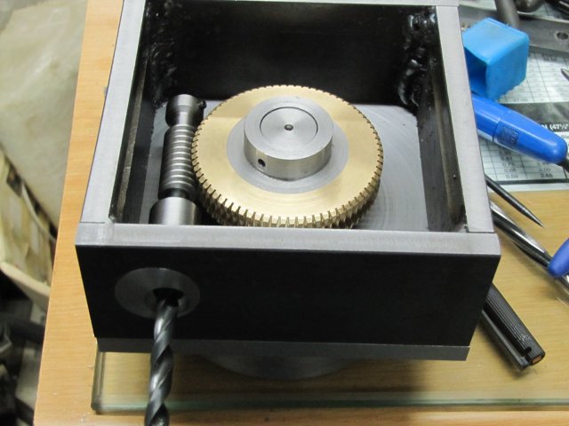
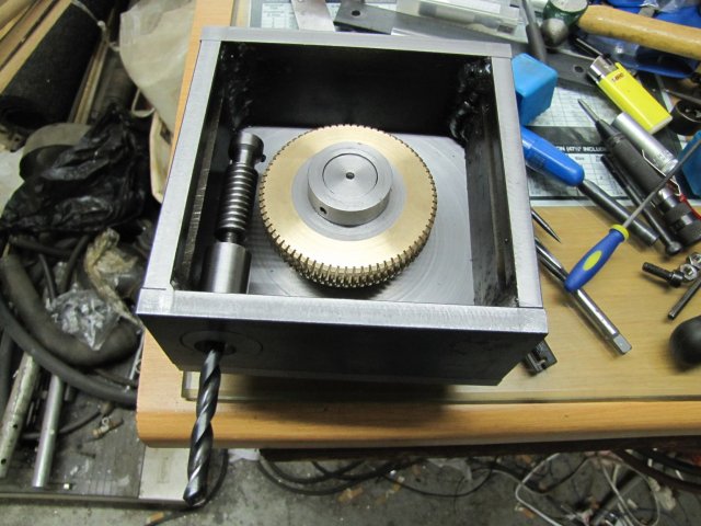
To test everything - the moment of truth - I installed one bearing on the eccentric, and with an 8mm drill as "shaft" tested everything. Next two photos show both the locked and unlocked positions:
normal_IMG_1327.JPG

normal_IMG_1328.JPG

I'm happy ;D - the worm is dead on position in the locked position.

Regards, Arnold
 
Arnold,

What an awesome job you are doing.

Perhaps I underestimated the $$ by quit a bit. :big:

SAM
 
Arnold, excellent work! The eccentric will be a nice addition.
You put two bearings in the eccentric housing, right? One in each end?

I still need to make or buy a boring head for the mill.

Make it! Make it! About $5 in my money to make one. I can't imagine what a factory made
one would cost in your location. Take the cheap way out. You were going to spend the time
in the shop anyway, right? :)

The one that Steve Campbell designed is very good, and could easily be adapted to your mill.
Just make it with a stub shaft on the end that goes toward the spindle, and hold it with a collet.
You can make it any diameter you like.

I'll put up a link for it if you want it.

I'd better let you finish your current project, I guess..
; )

Great work. I'm a fan!

Dean
 
Back
Top