Building a 120mm rotary table

Home Model Engine Machinist Forum

Help Support Home Model Engine Machinist Forum:

This site may earn a commission from merchant affiliate links, including eBay, Amazon, and others.

arnoldb

Well-Known Member
Joined
Apr 8, 2009
Messages
1,792
Reaction score
12
While building Elmer's Grasshopper, I saw that I could really do with an RT for my mill. I'm still broke from buying the mill, and an RT is pretty expensive here in Namibia.

Some research turned up bits and pieces of information on RTs, and then I hit gold on Dean's build of his rotary table - excellently detailed as always by Dean - and the plans available there. Thank you both Dean and Steve :bow:

My build is based on Dean's, but I'm adapting some dimensions and methods to the materials and tools I have available, as well as changing some bits to suit my own needs.
Some of the things I want from the RT are:
1. Use as much material as possible from what I have on hand or can economically obtain
2. An adapter to take any of my Myford chucks and to do machining securely on it.
3. Adjustment of backlash on the worm drive - and full disengagement of the drive for "quick indexing"
4. Accuracy to 0.1 degrees or better from the hand wheel, with an option to add dividing plates as needed.
5. Compatibility with as much of my existing tooling as I have.

As I have to make the worm and gear, I decided on a 72 tooth gear; that gives 5 degrees per turn of the hand wheel and should make things easy to use.

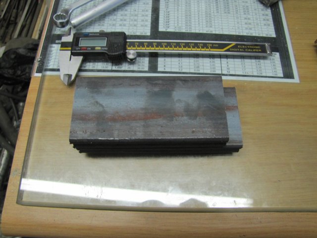
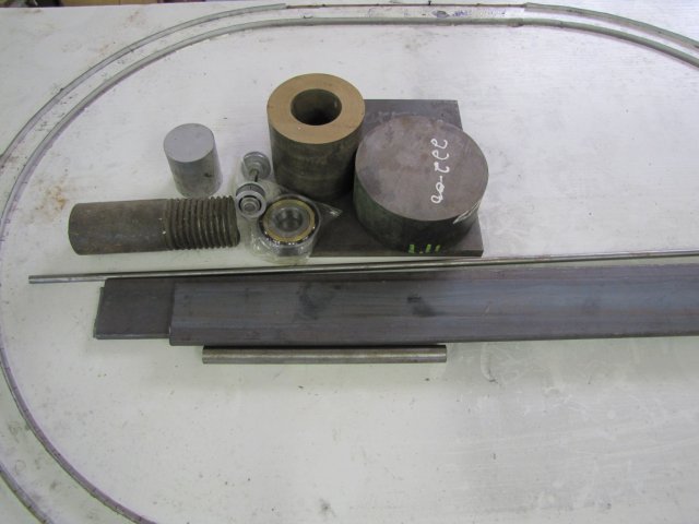
For the last couple of weeks, I've sourced and scrounged whatever materials I would need for the build; some I had lying around, and a lot I had to buy. I ended up with: Some bits of 10x60mm flat bar and a bit of 12mm plate for the base, a lump of cast iron for the table, phosphor bronze to make the gear out of, an old bit of bolt for some material to make diverse bits, aluminium for the handwheel, a brand new angular contact bearing, a bit of shaft from a printer with 2 small bearings to salvage for mounting the hand wheel shaft, and some 8mm and 16mm silver steel to make the shaft, worm and gear cutter from:
normal_IMG_1135.JPG


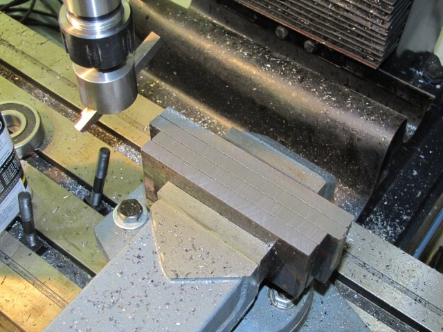
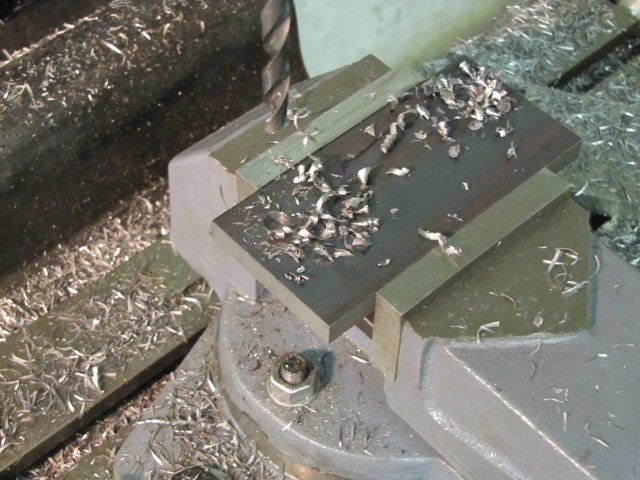
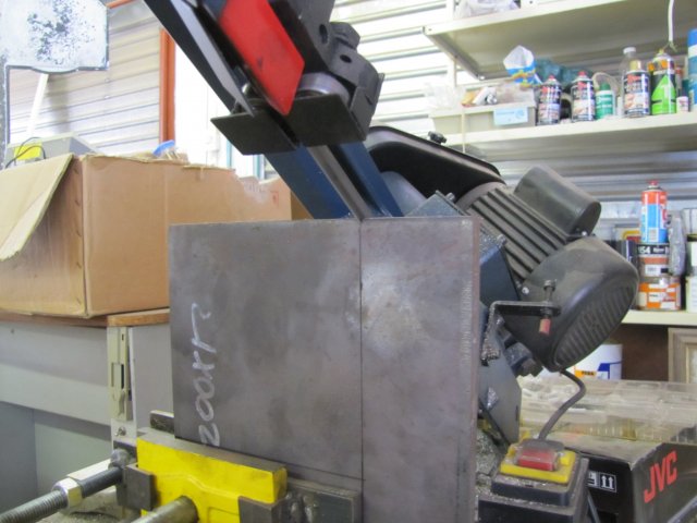
I started on the base; the bit of 12mm plate I had was too big, so I sawed it down in the bandsaw. It was a bit too big for the bandsaw as well; so I started with as much as possible of the plate clamped in the saw vise:
normal_IMG_1136.JPG


Then, when the saw frame bottomed on the plate, I flipped the plate around with less clamped to finish the last bit :
normal_IMG_1137.JPG


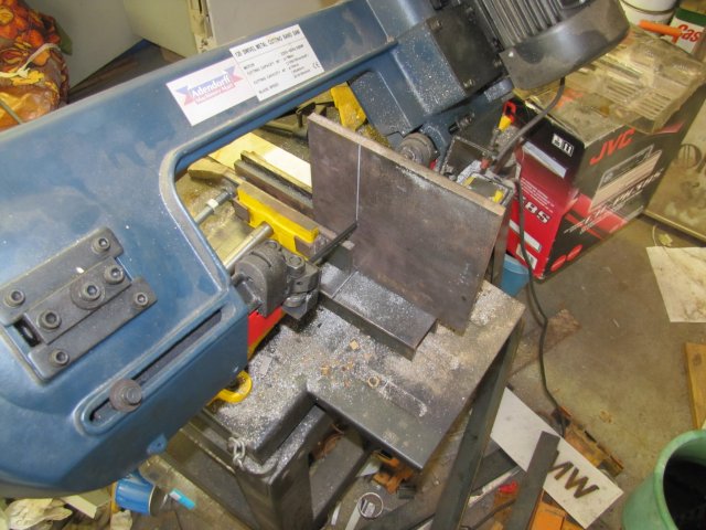
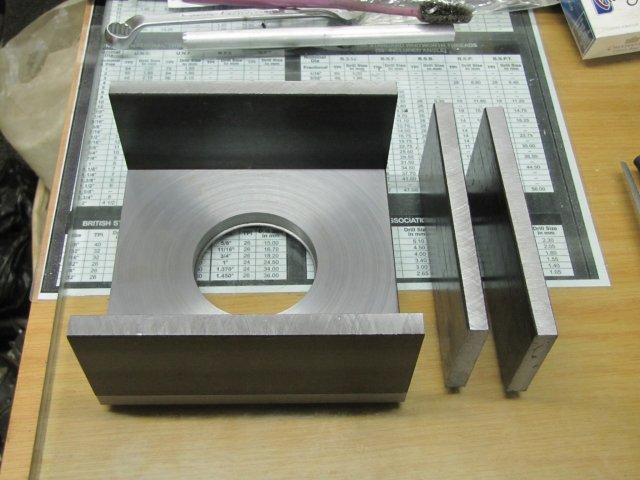
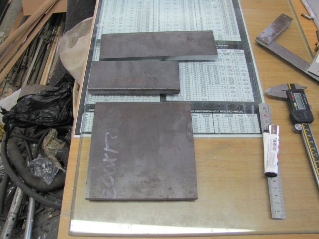
The last cut was done in one go, and I ended up with the RT base plate and some left-over bits of 12mm thick plate for other projects:
normal_IMG_1138.JPG


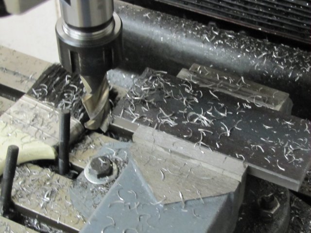
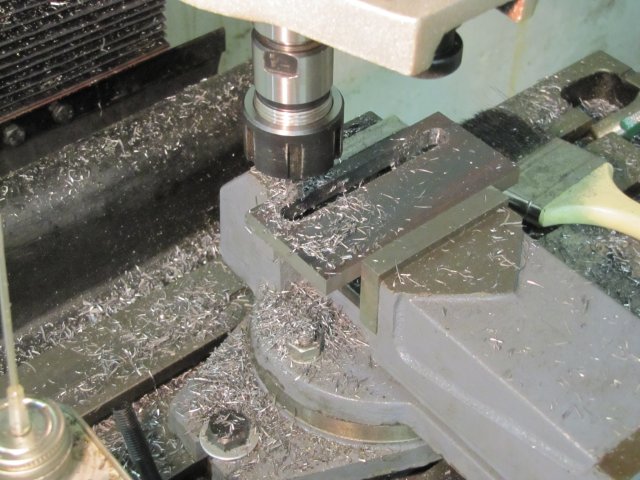
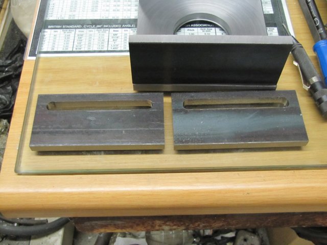
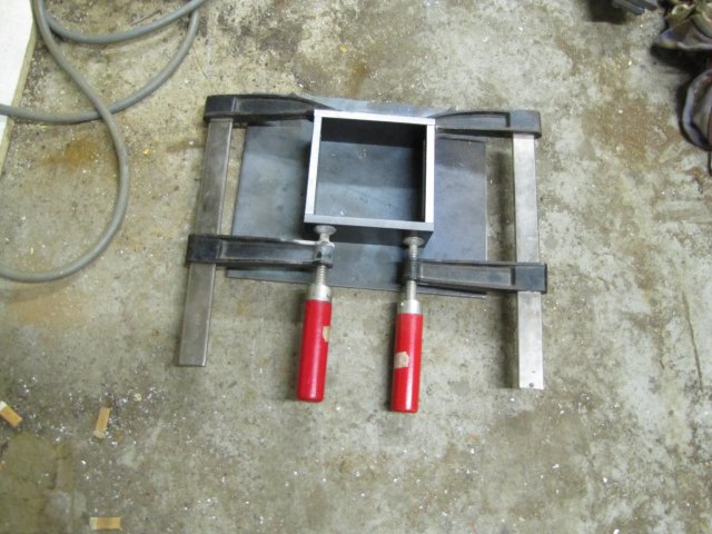
Then I clamped the plate to the mill table with some bits from the clamping kit and supported on two identical bearing outer rings as spacers, and milled three of the four sides square, with the two opposing sides I could get to, to the exact width for the plate (140mm):
normal_IMG_1140.JPG


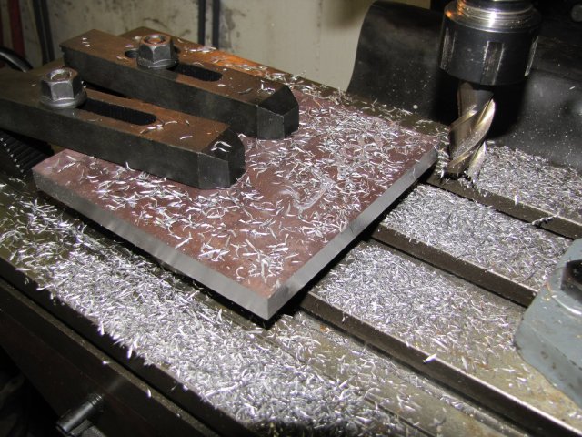
The last side of the plate was done by adding an additional small clamp on the opposite completed side to keep the plate in position, and then moving the main clamps over to the finished side as well to clamp down properly to mill the last side both square and to dimension.

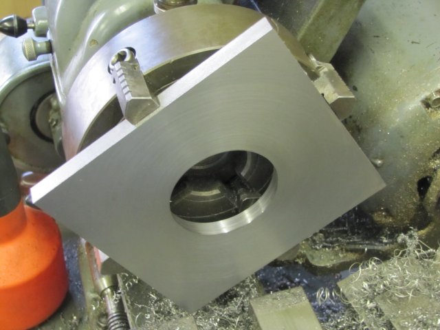
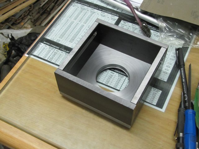
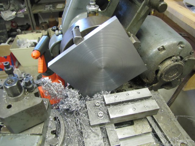
Fortunately, I could chuck the plate in the 4-jaw on my lathe; this makes it easy to face and bore the hole for the bearing. The corners barely clear the bed while swinging in the head-gap. :
normal_IMG_1141.JPG

To prevent the corners of the plate from hitting the apron while feeding, I just used the top slide to offset the toolbit enough. The cross slide is pretty close to maximum extension as well!

With the old Myford in medium back gear speed, I started the biggest facing cut I have tried to date. It took a while; very slow infeed at the start with interrupted cuts, and looking at the chips coming off to increase feed rate towards the center. Not a pretty picture, but the "ringy bands" looks worse than they are actually:
normal_IMG_1142.JPG

:-[ - I think some of those "bands" was caused by lighting a cigarette or two during the facing process ;)

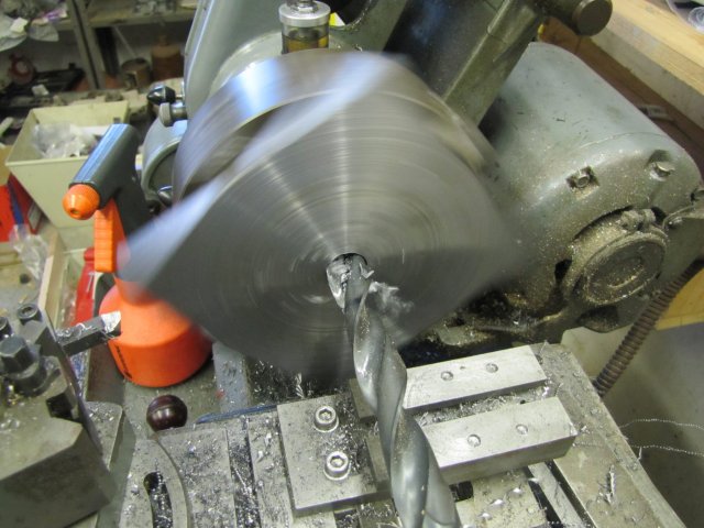
Next I center drilled, the plate, and drilled an 8mm hole through it with the lathe running at its second highest speed, followed by a 19mm drill (the biggest I have) in high back gear speed:
normal_IMG_1143.JPG


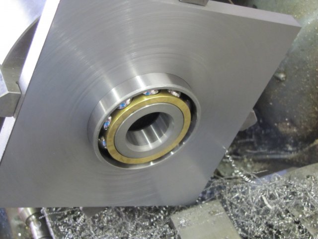
Then I bored the hole bigger; (from 19mm to 61.97 mm) I started with a cheapy tungsten carbide tipped boring bar and 20 thou (~0.5mm) depths of cut and things went OK until I tried some bigger cuts. At 40 thou cuts things were going well, but then the carbide tip splintered and everything ground to a halt. Not feeling in the mood to try and re-sharpen the tool, and with the hole big enough for my favourite HSS left-hand turning tool bit to have adequate clearance, I just plonked that in and finished the cut. I intentionally left a 0.5mm thick ridge about 2mm wide at the back.That is to allow the bearing I have to be pre-loaded without the center of it actually rising up and touching the bottom of the table later on :
normal_IMG_1145.JPG

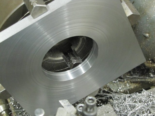
A test with the bearing showed that the hole is just about the right size for a press fit for the bearing, but with the plate a bit warm from machining, and the bearing cold, I decided to let everything cool down to the same temperature overnight to make sure of the final fit for the bearing.

Regards, Arnold
 
Oh, neat Arnold. This will be a good thread.

I've had a lot of people write me about this, and some ask about backlash take up. The only thing I came up with was eccentrics for the bearing cages on the worm shaft. I'll be interested to see how you do it.

Good luck with this new project. It'll sure be worth it in the end.

Dean
 
Good start Arnold Thm:

going to be an interesting build

Regards Rob
 
I to have read and downloaded the drawing in the link. I have started to gather the parts and actually started the the table with a 25lb cast iron weight. Mine will be 9".

So with that i will be following with great interest.
 
Thank you Carl - well, double thank you for your confidence! - I hope it's interesting, or at least informative in some fashion.

Dean, thank you. My first thoughts were also eccentrics, but that adds a kind of a "fiddly" factor to keep in place and mount and line up with the gear wheel . I'm going for a slot in the front of the table with a block that guides in it with a pivot block at the back into which the shaft bearings are mounted. At the back a similar pivot block but with a bush to give the shaft travel when adjusting. Not an entirely clear description - I know, and maybe a wacky layout - but I think it will work in the end. I received a quote this week from someone who I respect very much: "If you don't try it, you will never know if it would have worked." - So, I'm into a bit of trying ;D

Thank you Kevin ;D
Rob, Thanks mate ;D ... stickpoke :big: (inside joke ;D)

Hamstn, thank you. That's a nice big RT you are building then Thm: - remember we like pictures on HMEM ;) You might have to adapt some things for your own build though; you'll need a much stronger base for a start. And please don't take anything I do here as gospel; I 'm pretty much a newbie (and hard-headed at that), so some of the things I do or methods I use might not be entirely appropriate. Fortunately, there are a lot of skilled members here on HMEM, and I'm sure they will supply good pointers where/when it is needed.

Today was a bit slow; I didn't get as far as I wanted to, but some progress is better than none.

First thing, I picked up with the bearing fit, and as I thought, it needed some final sizing. With all the bits at the same temperature, the fit for the bearing would have been too tight, and I ended up taking another 0.02mm (a 0.01mm cut) out of the plate. Then the bearing was a nice hand press fit part-way into it's hole; the rest will need a bit of tapping with a hammer:
normal_IMG_1148.JPG


Then I flipped the plate in the chuck - just loosened two adjacent jaws of the chuck, flipped, and tightened down the same jaws, making sure the plate was flush on the chuck teeth with no swarf trapped. There was no need to perfectly re-center it - the last facing is just to get rid of the scale and to make sure the top face is completely parallel with the bottom. As the table will be riding on this surface, I tried to get a better finish - and succeeded:
normal_IMG_1149.JPG

After getting rid of the scale off the plate, I stopped and honed the cutting bit to get it really nice and sharp, thus the better result. The scale on HRS plate really blunts a HSS cutting bit quickly.

Next, some bits sawn from 60x10mm flat bar to make the sides of the base:
normal_IMG_1150.JPG


I just clamped the whole lot together in the mill vise and flycut the sides flat. A milling cutter might have been quicker, but once again, the scale on the plates would have made it blunt in short order. I can (and did - twice) re-sharpen the HSS bit I have in the flycutter. I also pushed things a bit hard; you can see the blue chips that came off; had me doing a dance while feeding getting hit by those :big: and a couple of times I saw sparks flying when some bit of "unknown" matter in the scale was encountered:
normal_IMG_1152.JPG


Then with both the longer pieces one-at-a-time, I squared the bandsawed ends down; one end just square, and then moved to the other end and squared , and then down to the 140mm length needed. After initially squaring the second end, I just measured how far it must be machined down (both plates were about 4mm too long at that point) and went down in 1mm steps on the mill hand wheels with the last step the required fraction of a mm on the hand wheel:
normal_IMG_1154.JPG

That 17mm end mill makes big chips on 1mm cuts and a vigorous feed ;D

End of work today; the top plate of the base finished, and the "long" parts of the base down to size:
normal_IMG_1157.JPG

The short sides still need to be machined to length. Most of the side plates also need some slot milling in them.
I've not made a final decision on whether to bolt everything together, or to weld it together. I'm thinking of welding the side-plates together, and bolting the top plate to them to prevent distortion on the top plate...

Regards, Arnold
 
Coming along well, Arnold. HRS isn't a lot of fun on a small machine, but we know it can be done up nice, eh? Thumbs up, buddy.
I think you have a good idea to weld up the sides then screw mount them to the top piece. The heat will surely take it out of square, but you can true it up before screwing down the top.

I hope you don't mind if I comment to Hamstn in your thread, since it looks like he's reading it.


Hamstn said:
I to have read and downloaded the drawing in the link.

Hamstn, please have a good look at the prints before you start, in case I've included any goofs!
(And thanks for checking out the article.)

Dean
 
I really appreciate the detail in your posts...for example...talking about the blue chips (and the dancing) and resharpening. It means a lot to me (and I'm sure other newbies) who wonder, not just if they're doing things right, but if others have the same experience.

It's a big reason why I like this forum...so many members do the same.

I have to admit...I'm hoping for bolting because welding is way beyond my current ability. ;D But do it the way you need to...I suspect welding removes the worry of things coming loose.
 
Great thread Arnold

That will be one handy bit of kit when done

Stew
 
be carful of that bearing in the fourth pic , i know its a sealed bearing but you never know
 
Thanks Dean - The old HRS can be a bit taxing; one day I want to get my grubby paws on some decent steel & see what the difference is. Most likely won't be able to machine it though :big:. Thanks - It'll be welded sides and bolted top then ;D And No - I don't mind any comments in the thread to others; "We" are all in this together :)

Carl, thank you. Remember, I'm a newbie as well ;D. I don't normally push my machines hard enough to make blue chips though. I like good clean chips coming off - I might be wrong, but for me it shows I have the right feed and speed going. The blue chips in this case was from pushing things to get trough the scale crust the HRS have - it blunts HSS cutters very quickly. As to welding vs bolts - I'm going with my own gut feel, but this job should work well just bolted together as well. The welding saves me from drilling and tapping holes and counterboring for screws and so on. The end result might be stronger as well. The downside, as I have mentioned, is that welding (stick welding in this case) cause things to warp. And the welds can look like chicken es-eightsh-eye-tee if I do it :big:

Thank you Stew - I can't wait to try it out! - A long way to go still though.

lordedmond, thanks for checking in, and welcome to HMEM. We're a pretty inquisitive crowd ;) - It would be nice if you post an intro in the welcome thread. And no worries about that bearing - it's a bust one waiting to be disassembled into bits to act as parallels :)

I had a bit of time in the shop after work... A bit disappointing at times, but not too bad.

I milled both the "short" sides of the base square and to length. As I'd decided on welding the lower part of the base, I thought it prudent to mil the clamp-down slots in these as well, before welding things together. For milling the 10mm slots, I marked and drilled 8mm holes at the ends:
normal_IMG_1159.JPG

While locating the holes, I set the mill's x-axis stops, which I have not used thus far, to stop on the holes - so I could do incremental cuts and just stop at the ends without looking at the hand wheels. Disappointment; I have not looked closely at the stops supplied with the mill, and thought they were steel, but it turned out it was plastic looking (and feeling!) like steel. Found that out when tightening the first one down; It went kgrrk and cracked on me. Another mill mod chalked up!

I bought a new 10mm HSS slot mill on Saturday, and set about using it to mill the slots between the holes:
normal_IMG_1160.JPG

On the first slot, things didn't go entirely to plan though... The milling bit easily chewed out the slot with 2.5mm down feeds on each pass. Then I got greedy; and tried a 3.5mm down feed... No problem for the cutter; it worked happily, but left a much rougher finish on the sides of the slot - that seemed to get worse as I went...
By the other end of the slot, I could visibly see the slot was a LOT (~1mm) wider than at the start. I did lock the y-axis on the mill, but it shifted. Note to self! - lock down harder and don't get greedy. I ended up with an 11mm slot and rough edges. I smoothed both sides of the slot out with some fine milling cuts to look OK - with a very fine climb-milling pass (0.1mm) on each side - fortunately the clamp-down slots are not crucial in size.
The slot on the other piece went much better; I wasn't greedy. I'll have an RT with one wider mounting slot. I could have milled the second slot to match the first one, but I'll leave it as is - as a permanent reminder not to be greedy in future ;D
And another thing, from now on, if I want a slot of "x mm" size, I'll make it with a cutter of "x-1 mm" size and have some clean-up room left!

The plates with the slots - with the over-large one on the right-hand:
normal_IMG_1161.JPG


Mock-up of base - some welding required :) :
normal_IMG_1163.JPG


Regards, Arnold
 
Hi Arnold
Nice work so far, I enjoy seeing the mods/improvements you have been making to your machines.
On your last pic I noticed the thread table underneath has British cycle thread on it. Just wondering where you got that table as it looks useful
Cheers
Byrne
 
Arnold the RT is going to go well, nice work till now!

on the greedy subject :D ... these milling machine are the culprit!
I broke a 16 mm mill after 5 minutes that I have had the new machine: to try it I started on a piece of alu with a cut of 1 mm, then 2 mm, 3 mm, 4 mm, 5 mm... crack
and sometimes I make the same errors also now: the man IS greedy :big: and these (relatively big) machines are a temptation :big:

 
Thank you Byrne :). Yes, the table you saw is part of a larger sheet (A3 size) that I leave below my glass "surface plate". It has tables on it with thread specifications and drill sizes for a lot of the different thread types (Metric, BSW, UN, BA, BSC etc) and is a reduced version of a sheet that Somta (a South African company that makes milling & drilling bits etc) issued at one time. I wish I can get my hands on an original sheet to hang on the wall! It is indeed very handy; it allows me to look at different treading requirements and translate to the closest metric equivalents which I primarily work with. I can't share a full copy of the sheet, as I think it may be copyrighted, but it is easy to build up something similar for personal use from information off web sites ;D

Ariz, thank you ;D - I'm happy to know I'm not the only one getting greedy then :big: Fortunately I've not broken any cutters on the mill yet - now I just jinxed myself ;D

Well, no more progress on the rotary table, but another arrival in my shop this evening:
normal_IMG_1164.JPG


It's a "Standard" - that's the make - power hacksaw that a friend is leaving with me for long term storage... I can use it as I see fit ;D
It needs some cleaning, and TLC in general, but appears to be in pretty good shape below all the gunk. The only major problem I can see after a cursory inspection is that it's coolant pump is completely frozen up; I hope I can repair that.

If anybody has any information on this machine, I'd really appreciate it. I know GIYF, but a search on "Standard Hacksaw" returns an overload of information on "standard hacksaw" and very little on "Standard Hacksaw" - So far, Ive only been able to establish that the "Standard Hacksaw Ltd" was taken over by Spear & Jackson Inc in 1970 - which makes this saw British and most likely built before 1970 ?

Its a HEAVY bugger - must weigh in at somewhere around 100kg - and it does not look that heavy. I had to provide my friend with copious amounts of beer to recuperate after we unloaded it! I think some more beers at a later stage might make him consider selling it to me ;D - or at least forget that he left it here :big:

Regards, Arnold
 
This seems like a very ambitious project to me and I'm just getting up to speed on your progress. Sure looks great so far. The flycutting operation on multiple pieces of stock held in the vise caught my attention. When I've tried doing this with an end mill and a depth of cut in the neighborhood of 0.020", invariably one of those pieces will slip on me. I have an inexpensive Chinese made milling vise and wonder if that's the problem ??? Or can you get away with this in a flycutting operation because of the lighter cut ???

Anyway thanks for posting this project.

Cheers,
Phil
 
nice hacksaw you just cant beat them for cutting all sorts of stuff

really enjoying the build Thm:
 
Phil, New_Guy, thank you for having a look and your comments :).

Phil, yes, maybe it is a bit ambitious, but I like pushing my skills to the limit and a little beyond; that's the only way to learn. So far things have been fairly common machining operations. Saying that, a year ago I couldn't even turn a good press fit for a bearing, so the "common" is used loosely ;D - things just become easier as one goes along.
The flat bar I'm using is fairly rough on the surface - that helped with clamping them together. If it was smoother and I thought the pieces might slip, I would just have put some strips of paper between them. I also have an inexpensive Chinese vise - but I made some changes to it to function a bit better; added shim plates to prevent the movable jaw lifting as much as it used to, and also cleaned up the screw in the lathe with a file to make it smoother in operation - this makes it easier to really tighten workpieces up.
I think the flycutter might make a tiny bit of a difference, but not really much. And I was pushing my flycutter really hard; 0.5mm depths of cut - which is pretty close to your 0.020" - and BIG cuts for a flycutter. Like I said, whenever I could detect the cutting bit in it getting dull, I'd stop after that pass and re-sharpen it. Much cheaper than stuffing up end mills :big: - just takes a bit longer to machine.

I welded up the base frame after work today.

First I clamped the bits of the frame together on the bottom of the base top where it would mount. I did this to make sure that the clamping didn't push things out of kilter, and it also allowed me to make final adjustments with a small hammer to get everything lined up as close as possible:
normal_IMG_1165.JPG


Then very carefully shifted the clamped assembly over onto a spare piece of plate to make sure nothing shifted, and put the whole lot down in an open space on the workshop floor for welding together. (I have a steel workbench for this kind of thing, but it is too cluttered right now :-[):
normal_IMG_1166.JPG


Four good tack-welds with the stick welder mid-way on the inside of each corner to prevent distortion as much as possible, and then a lot of welding followed. All welded up on the inside corners:
normal_IMG_1167.JPG


Not a pretty sight :hDe:; I only had 2.5mm welding rods on hand, which were a bit small for this job, and the thick metal seemed to conduct a lot of heat away very quickly while welding, so my little AC welder struggled a bit even on it's maximum current setting. One day, I'll get myself a bigger DC inverter welder (or a MIG ;D):
normal_IMG_1169.JPG

:hDe: To be honest... My welding skills suck and need improvement.

Regards, Arnold
 
Arnold,

It's coming together nicely. :bow:

For a corner fillet weld such as those, it may help if you grind off half of each corner on the slotted plates giving a 45 deg V. This will help to ensure the weld gets good penetration and strength at the same time as allowing you to retain the original edges for alignment.

Looks to me like you are using a 240V single phase welder. In Oz I would use a Satin craft 13 electrode as these have a slower flux than a Satin craft 12. This helps stop the flux from running into the weld pool and stopping the arc. My welder has only 2 settings 2.5 and 3.2 mm so I try and use the shortest possible cable between the power point and the welder. If I have to go longer a heavier duty cable helps keep up the volts and amps.

Best Regards
Bob
 
Arnold, Bob,

You can preheat the parts with a propane torch (the kind you would use for plumbing) or something like that along with a bevel to get better flow of the welding rod.

Regards

Philly
 

Latest posts

Back
Top