Brian builds Atkinson Engine

Home Model Engine Machinist Forum

Help Support Home Model Engine Machinist Forum:

This site may earn a commission from merchant affiliate links, including eBay, Amazon, and others.
Ah, I see. When you refer to your "jitterbug" sander, is that an orbital sander?

Thanks,
Todd
 
Looking great Brian, what size is your mill my I ask? You have your plate extended on all extremes. I am still here following with interest.

Don
 
Looking great Brian, what size is your mill my I ask? You have your plate extended on all extremes. I am still here following with interest.

Don
My mill is a Busybee CT129 It has a maximum left to right travel of 11 1/4", 5.5" the other direction, and a 2" quill stroke.---and I think its a 3/4HP motor, with an MT2
taper in the quill.
 
This is the finish I was able to achieve after about 5 minutes using 120 grit paper on my jitterbug (orbital) sander. Some of the marks left by flycutting were quite deep. (estimate about .005")--enough to be very visible, so required a fair bit of sanding to get all the swirl marks out that were left by flycutting. The current finish is quite acceptable, but I will use a sheet of 320 grit to give it a bit more dressing before I dismount it from the bench. One of the things you will notice, although I showed no pictures of the process, is the 3/16" x 45 degree chamfer all around the top side. I did this with a 45 degree chamfering endmill while I still had it set up in my milling machine.
BASEPLATEFINISH001.jpg

BASEPLATEFINISH002.jpg
 
Well of course I write notes to myself all over the parts I'm drilling and counterboring 20 holes in!! Doesn't everybody???
NOTESONPARTS002.jpg

NOTESONPARTS001.jpg
 
Woo!!! You are a speed star, dog gone Brian, do you sleep? That looks awesome. You are making short time of this project. Beautiful work as usual.

Don
 
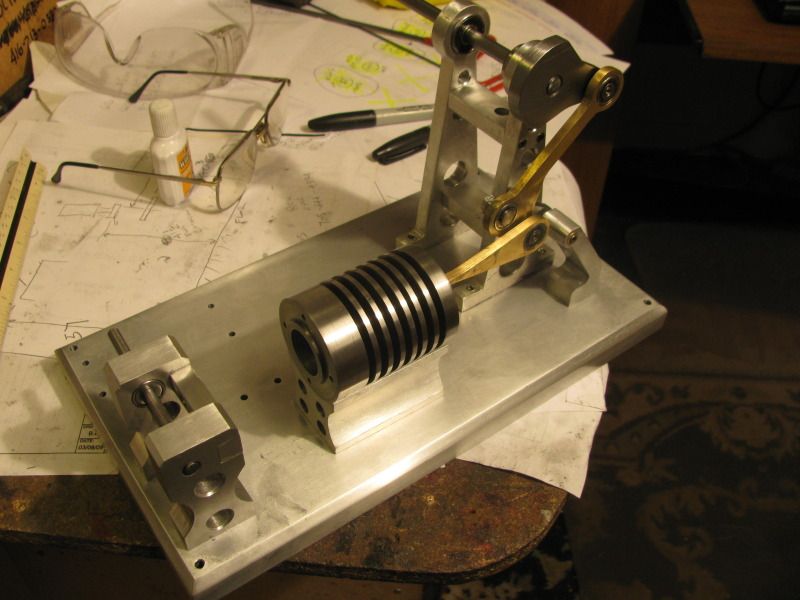
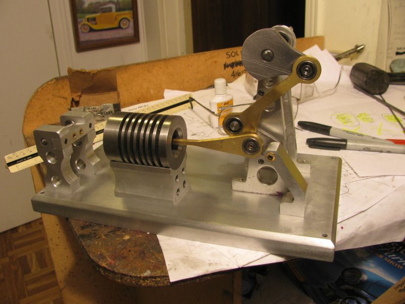
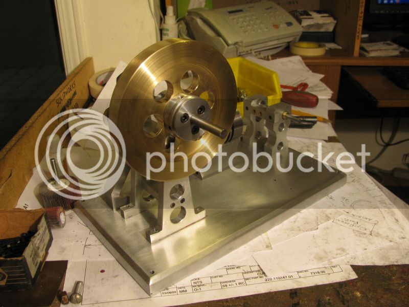
Its always a huge relief to me, when I get all of the major peices assembled on the baseplate and everything rotates as it is supposed to. On one level, I know it will, because it does on the 3D cad model. However, on a strictly "machinist" level, I always hold my breath a bit as the peices go together, even though I'm the one that created the 3D model. Will everything rotate without interferance??--Will the piston stop at both ends of the cylinder where it is supposed to???--Will my sub assemblies be drilled and tapped accurately enough to match up to the baseplate holes without having to resort to "stretched holes"??? I guess we all have that same amount of trepidition when building any peice of complex machinery. Perhaps its something I will outgrow if I stay in this machining hobby long enough, but today I am relieved. When I posted the assembly picture last night, I didn't have either of the #10-24 x 2" shcs that hold the cylinder in place. This morning I drove down street and picked them up, and bolted the cylinder securely to the baseplate. Everything goes "round and round and up and down" just like its supposed to!!!----Brian
 
Nicely done Brian. Looking forward to see it run.

Vince
 
I guess we all have that same amount of trepidition when building any peice of complex machinery. Perhaps its something I will outgrow if I stay in this machining hobby long enough, !----Brian
Brian, I've been following your builds in silence for sometime now, always delighted with your designs and problem solving,as to your trepidation, I've been building molds and various little machines for some 35+ years now,that never goes away,I always wonder until the last screw goes in, I don't think that ever goes away,at least I hope not, how much fun would that be?:rolleyes:
Gimpy
 
This afternoon we have a 5" diameter chunk of brass and its mating aluminum hub that are destined to become a flywheel assembly. Unfortunately, my toolshop dropped the ball and didn't get me the 8mm reamer I ordered earlier in the week. I would take a chance and bore the brass to an exact 8mm, but that chunk of brass is worth more than the first car I bought, so I will wait untill my reamer comes in.---Don't want to screw it up!!!
flywheel-3001.jpg
 
This morning I decided that since 8MM is 0.3150" and 5/16" IS 0.3125" I would go ahead and finish off the flywheel using a 5/16" reamer. I can open that out to 0.3150" when my 8mm reamer comes in. I like the way Jan designed the bolt on pulley/hub combination. There are three 1/4" set screws arrayed at 120 degrees around the hub to secure it to the shaft, and three #10-24 shcs to secure the hub to the side of the flywheel.
flywheelassembled-2002.jpg
 
Nice looking flywheel assembly. Don't get too far ahead of yourself, but that hole was safe.

Work on my man. Doing good.

Ray
 
So now I'm stumped!!! The petrol vapour gas tank for this engine requires a peice of clear glass 1 7/16" diameter x 1/16" to 1/8" thick. Nobody in Barrie knows where I can get this. I was thinking about the glass lens from an old flashlight, but I just came back from the hardware store and all the flashlights are plastic now. Anybody have a suggestion?
 
Do you know anybody locally with a waterjet cutter? I could cut them for you for the cost of shipping, but I hear that can be expensive going over the border.
 
Hi Brian

I would check at your local watch repair shop. Pocket watch crystals come in many different sizes. They won't be 1/16 thick but will be plenty strong enough for that application.
Thanks for your time and energy you spend on your posts, it's appreciated by many of us. Some K your way.
Regards Gary:)
 
You have done it again Brian.:)Just beautifull.
Ian (seagar)
 

Latest posts

Back
Top