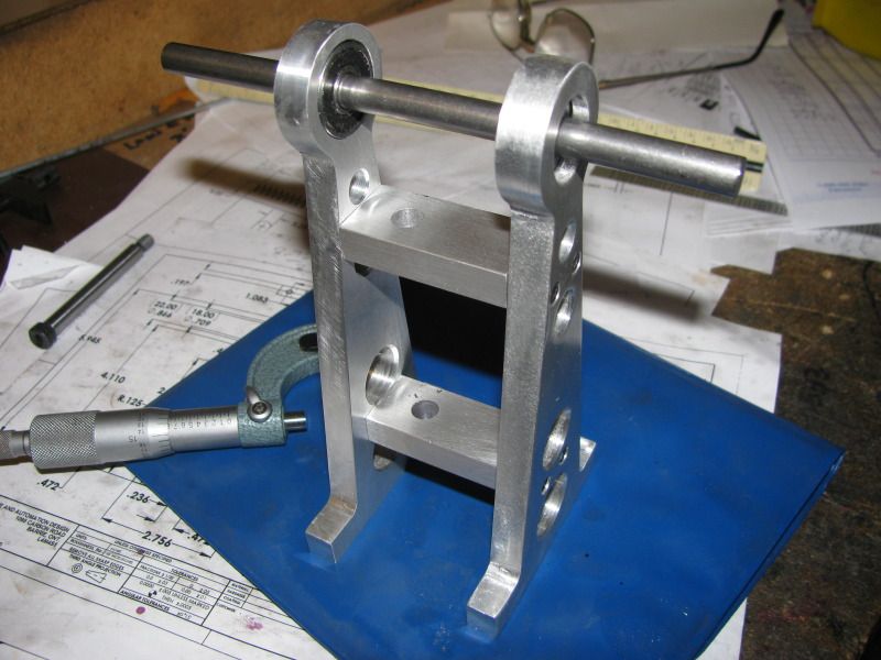
Brian builds Atkinson Engine

Home Model Engine Machinist Forum

Help Support Home Model Engine Machinist Forum:

This site may earn a commission from merchant affiliate links, including eBay, Amazon, and others.
Hi Brian,

I am quite new to the community and it is the first time I am following your work. You make it look very easy hope I will get near with time. English is a second language for me and sometimes I have to read the same part many times to understand. It is nice you take all that time to post with all the details. Keep going, I will be following.

Mario
Mariom---Welcome!! Glad you're tuned in. Your English is fine.---BRIAN
 
I got up this morning, did a couple of hours of "real work" for one of my longstanding customers, then spent a couple of hours machining the cross bars which fit between the flywheel shaft supports. Now I ABSOLUTELY can not do any more machining untill I tram my mill, an exercise which I am rather dreading, as I have never done it before.
cross-ties002.jpg
 
Brian you project is looking good, and I am sure a man of your means will have no trouble tramming a mill.

Don
 
Hey Brian, nice progress on the engine. You sure are cranking out the parts.

Tramming your mill isn't particularly difficult. It can, however, be tedious and frustrating.

Chuck
 
G'day Brian,this old Aussie is still following your build.I have always enjoyed your builds and learned so much from you .Keep up the good work,your one of the best.

Ian (seagar)
 
Chuck--I'm so glad you're still here. I was afraid I had lost you. Seagar, its nice to hear from you. This project is interesting, and it keeps opening up new vistas for me in the world of machining.----Brian
 
You are trucking right along Brian. You must live on coffee :)
 
I decided that before I got too carried away with the base, I should complete the gas tank and be sure of the footprint it would require. Jan Ridders calls up for his "Petrol Vapour Carburetor" to be fabricated from 45mm diameter brass tybe, which is roughly 1 3/4" in diameter with a 1mm m(0.039") wall.I decided to cheat a little bit for the sake of economics, so went up to my local hardware store and purchased part of a batheroom sink drain for $7.00. It is only 1.5" diameter, but I will make it a bit longer than the one in Jans plan to compensate for the difference in volume. This part has only a 0.23" thick wall, but as it doesn't have to hold any pressure, I'm sure it will be o.k.
GASTANK-1003.jpg
 
Hi Brian,

I'm new here too. But, I'm sure glad that you have stuck around through the change. You work is amazing to study. I learn so much from reading build threads like yours. Thanks for sharing you talents here.

Todd
 
I've had to modify Jan Ridders design a bit, but the operating principle will be the same for the "petrol vapour carburetor'. Unfortunately, I have some real work today, so can't persue my "Play work" any farther untill I make a customer happy----
GASTANK-FULLASSEMBLY.jpg
.
 
Brian you seem to make things interesting I enjoy following you.
Great progress so far.

Don
 
Bryan, Great work, and yes I do follow your work. Post or no post on my part I'm here watching, and learning, Thank you very much .. larry
 
This morning I was looking for something simple to make. I decided to forego brass for a change and whittle something out of steel. Now the drawing I have shown is a direct rip off of Jan Ridders drawing. Don't worry----I'm not going to give away the plans to Jans engine-----This one is slightly changed, and there will be more changes as I proceed. After taking a good look at this drawing, (On which I have changed the bores to suit my British Imperial reamers) You will see a small hub stuck out to one side of the main plate. This means that I would have to machine away a lot of steel from a 1/2" plate to end up with a 5/16" thick plate with a hub stuck out to one side. Steel is not one of my favourite things to machine. You will notice that the ONLY critical areas on this whole thing are the diameters of the bores, and the center to center distance between the bores. Everything else is "clearance". Normally, for a big radius like is shown on this part, I would set up my rotary table and mill it in a perfect arc.---However, thats a lot of work, and not really necessary to the function of the part, so I will cut it out on my bandsaw, leaving just enough material to "mill to the line", only instead of using my milling machine and rotary table, I will use my big old vertical belt sander that I built back in my hotrod fabrication years for smoothing the edges of flame cut brackets, and "sand to the line" with a 36 grit belt. I will fabricate the hub as a seperate part and silver solder or mig weld it to the main plate. Then, after the hub is attached, I will clamp it to my mill table with a sacrificial plate underneath it and drill/ream the two holes. I won't use my mill vice for this operation, because the moveable jaw "kicks up" when I clamp something, and the squareness of these holes to the surface of the plate is fairly critical.
CRANKWEB.jpg
 
Here we go with some "Step by steps'. All of you senior accomplished machinists can ignore this---mostly its for the Newbees out there. First we start out by laying out the shape of the crank throw as accurately as we can on a peice of 2" x 5/16" cold rolled steel bar, coated with layout dye.
CRANKTHROW001.jpg
 
As usually happens, my plan of attack changed a bit---I had to clamp this part to the mill table first, with a sacrificial aluminum part underneath to cut the 3/4" holes which form the inside corner .375" radii. Then I thought while I had it all well secured---Ah, Heck---lets do all the holes---So I did. The 3/16" hole is drilled and reamed. At the other end I drilled and reamed a .437" hole. The "add-on" hub will have a section turned to 7/16" diameter and be drilled and reamed to .312" in the lathe, then press fitted and silver soldered to this crank throw.---By the way--those 3/4" holes which form the inside radii were first drilled through with a 1/4" drill, then enlarged in 1/8" steps with a series of 2 flute end mills, up to the finished diameter of 3/4"..----And Oh yes---I used the dials on the table to move the exact distances required. My punch marks were only there as a guide to keep me from making an error when counting turns of the dials. I have no electronic positioning devices on my mill.

CRANKTHROW001-1.jpg
.
 
Let me introduce you to the "Machinists Friend"!!! I built this about 25 years ago----It has a 2 HP motor on it, and will eat metal as fast as I can push it into the belt!!! It has saved me untold man hours on non critical surfaces.
CRANKTHROW004.jpg
 

Latest posts

Back
Top