That is the most interesting stroke action I've ever seen. I love to watch a Walschaerts valve gear in operation. But, this is new levels of fun to watch. Thanks for sharing the video Brian. I've been wondering how that was going to work. I'm really enjoying this build.
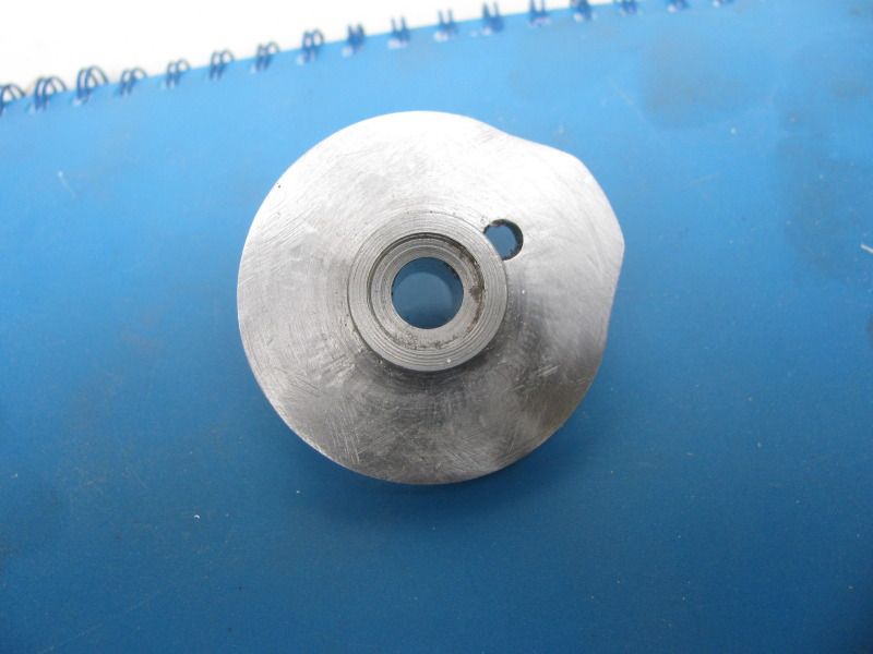
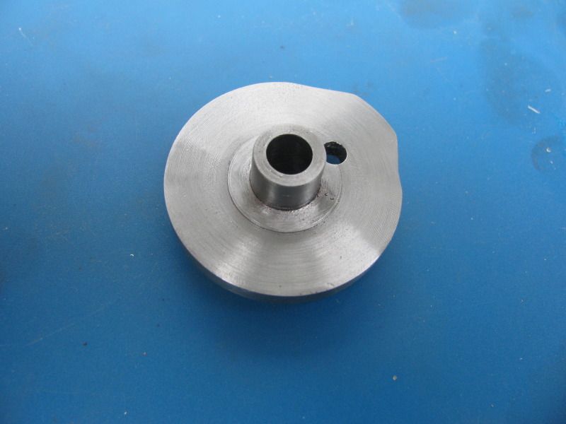
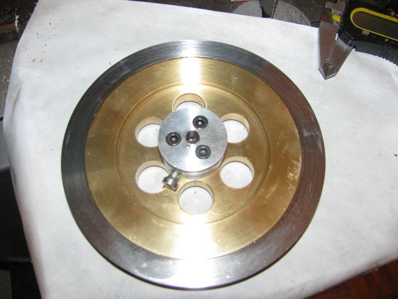
Dear Lord in heaven---I'm glad that I don't do this for a living!!! It's taken me four hours to make this ignition cam, (chatter marks and all). I's 12:43 now, and I started hogging this out of a peice of 2" round cold rolled steel this morning about 8:30!!! Granted, there's a lot going on there---turning, facing, rotary table work, drilling, reaming, and drilling and tapping 3 set screw holes that don't show up in the picture.--Still, thats a heck of a lot of time for one measly peice. Ah well, its one more part finished.----Brian
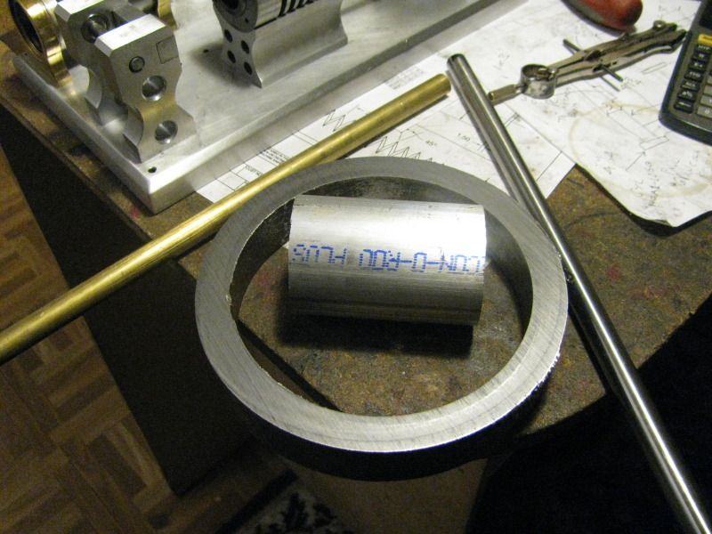
I went down to my favourite store today and bought a peice of 2" dia. aluminum to make the cylinder head ---(I only needed an 1 1/8, but I needed an inch to hold onto in the chuck, and an inch in case I buggered something up.) I bought a foot of 1/2" dia 01 drill rod to make the valves (and possibly a valve seat cutting tool) from, and a foot of 1/2" brass for the valve cages. Ever since I made the flywheel from my chunk of 5" diameter brass, I've been trying to convince myself that 5" would be large enough in diameter, despite the plans calling for a 6" diameter flywheel. Today I asked while I was down there how much it would cost for a 1" long peice of 6" o.d. x 4 7/8" i.d. heavy wall steel tube, and was told $5.00. This being the case, and being rather inclined to "Better safe than sorry!"), I bought a peice, which I will bore for a precision fit on the outside of the brass flywheel and face the sides to match the brass. I will Loctite it onto the o.d. of the brass flywheel.
I have been following along and enjoying your great build post! The video is also very nice and makes it easy to see all of your progress on this interesting engine.
Thanks for taking the time to share your build with us.
Well there!!! My formerly 5" dia. flywheel is now a 6" diameter flywheel. My 10 x 18" lathe with its 5" chuck was right at the maximum to even hold the peice of tube for machining. I clamped it from the inside and took a clean up pass on the outer diameter and the exposed face. The peice of tube was 1" long, and the jaws used up 5/16" of that, leaving 11/16" clear on the inside to bore it to the 4.95 inner diameter to match the o.d. of the brass flywheel. Then I match marked the tube to one of the jaws, flipped it around in the chuck, and proceeded to machine it down to the same width as the flywheel. The brass flywheel is .630" wide. I didn't trust the strength of my set-up, so I took facing cuts of .005" on each pass.--That works out to 75 passes, holding my breath on each pass. Once I had the tube to the correct diameters and thickness, I used a liberal application of emery paper untill all machining marks were removed. I didn't have any waxed paper so I got out my can of Johnsons paste floor wax that I've had ever since my fiberglass body days, and waxed a peice of printer paper to set things up on. The table of my bandsaw is a machined surface, so I cleaned up the i.d. of the tube and the o.d. of the flywheel with some really "hot" laquer thinners, set the ring on the waxed paper, coated the outer diameter of the flywheel with 638 Loctite and tapped it into place with my dead blow hammer.--And how did you spend YOUR afternoon???
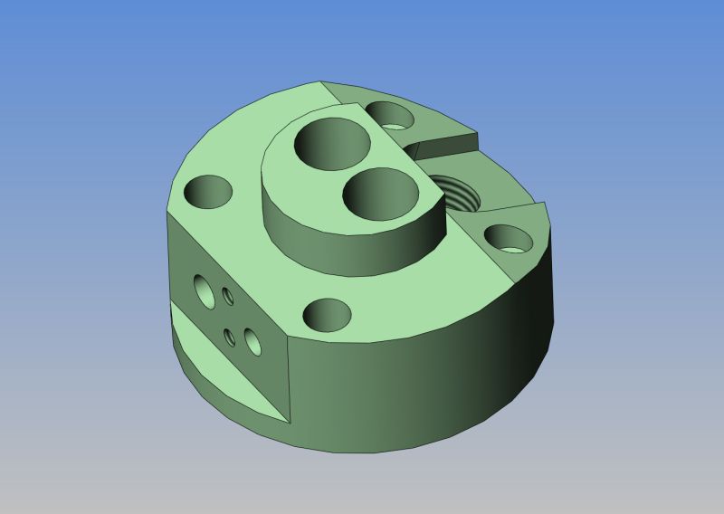
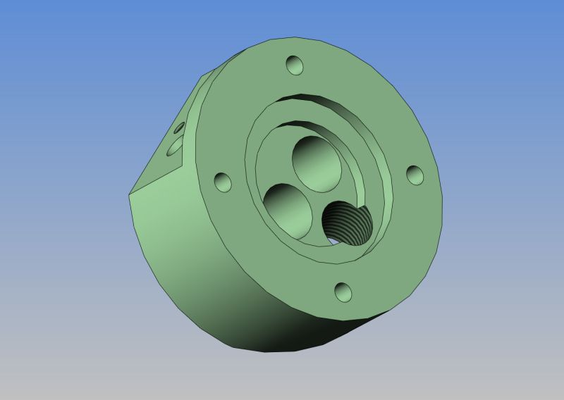
Now that we have the flywheel issue resolved, we're going here next. The cylinder head. Its made of aluminum, its 2" diameter, and its a busy little devil. There is a lot going on here. I also changed the threads for the sparkplug to M10 x 1 so I could use a locally available sparkplug.
Life never gets dull around here. Today my back is killing me from doing so much machining lately. So----Time for some CAD work. On both the Webster and the Kerzel I.C. engines I have built, I used a set of early Chrysler ignition points. Although Jan calls up for a piezzo electric ignition on his Atkinson engine, I am not going to go for nearly as sophisticated a solution, but will instead use the same ignition points on this engine. I could have swore that I modelled these points before, but a search of all my hard drives and discs yeilded nothing, so this afternoon I pulled the points off my Webster long enough to model them and their mounting plate. Tomorrow I will model up some simple way of mounting these points to the Atkinson engine.-And Oh Yes, I buy these points at PartSource, they are made by BWD Automotive on Long Island and the PartSource number is 018-4126-8 A110P--Brian
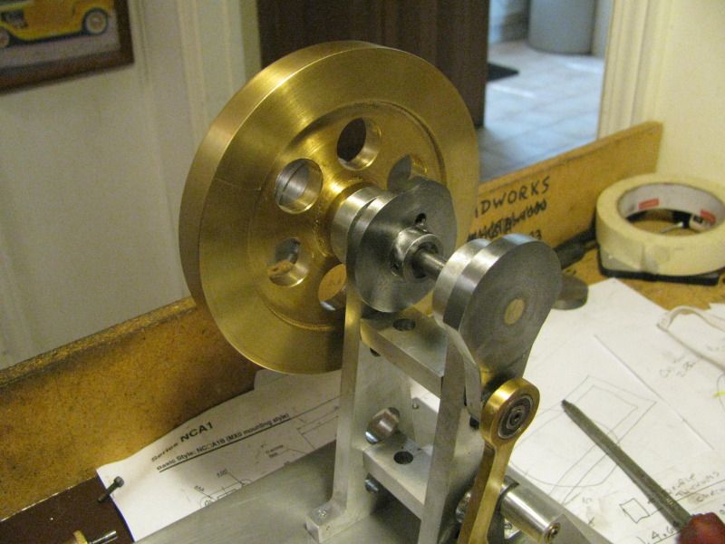
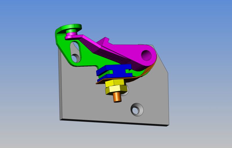
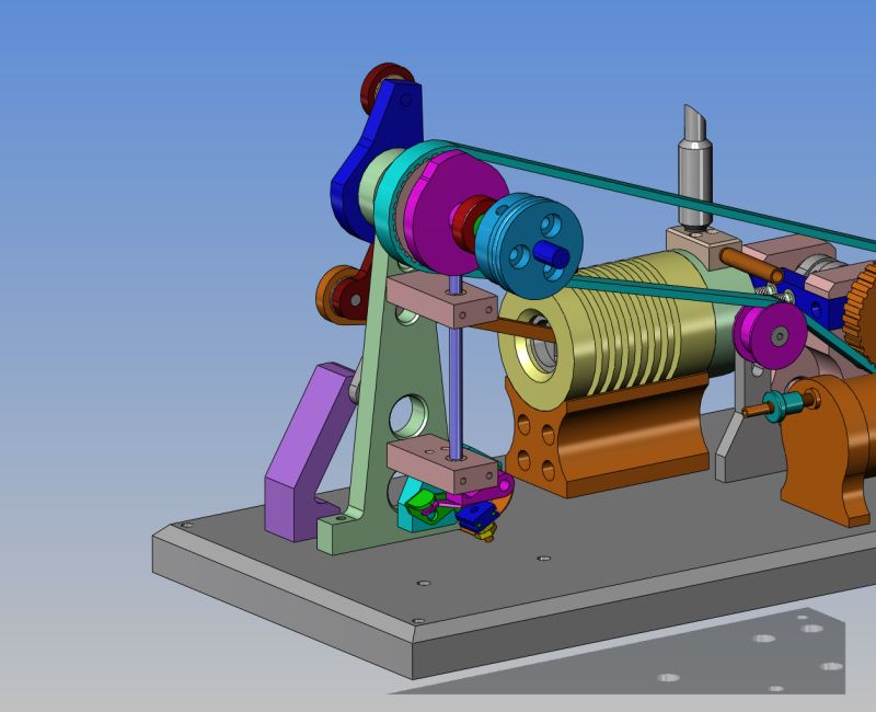
I've found a good place to mount the ignition points. They are mounted on the blue 3/8" thick peice of aluminum which is bolted to the lower cross brace between the flywheel shaft support towers. A peice of 3/16" round brass rod is mounted in guide bushings between the ignition cam and the ignition points rubbing block. In the picture I have hidden the one support tower and the flywheel so the points, mounting block, and activator rod are visible.
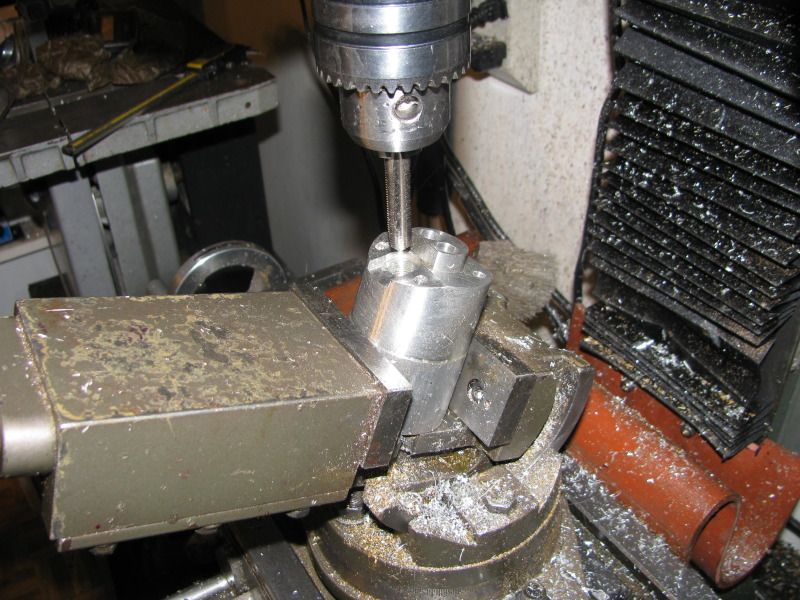
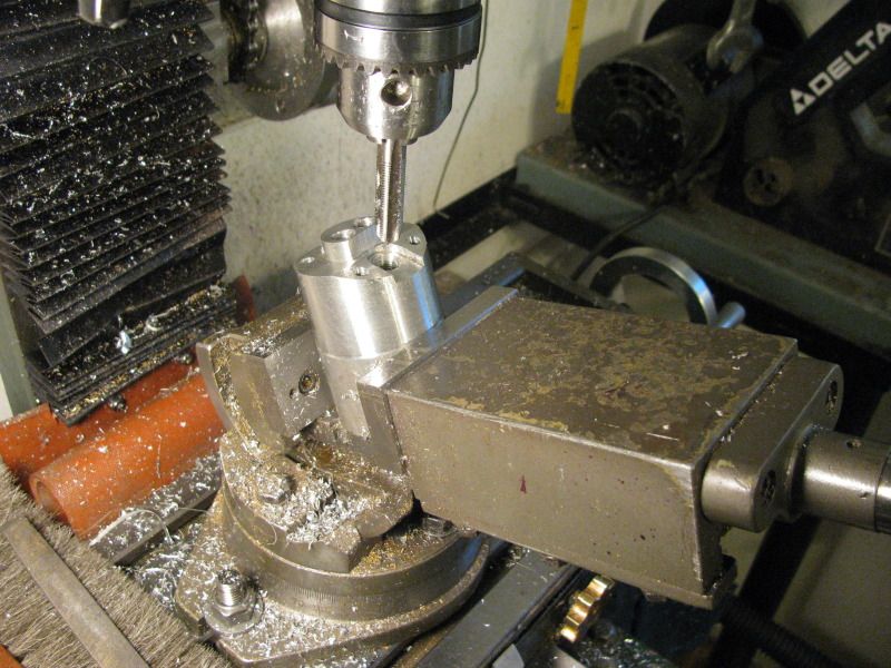
This is my 3" length of 2" dia. aluminum well on its way to becoming a cylinder head. Other than "facing" both ends of the blank, all of the work so far has been done from one end. The current pictures show me putting in the sparkplug threads (M10 x 1) on a 20 degree angled face. This is where my cheap nasty tilting vice really shines. It, combined with my digital level lets me make some very accurate angled faces and holes that I would otherwise find very difficult. I wasn't power tapping the hole--Its just that with the tap locked in the chuck and then turned by hand, I never have to worry about crooked threads. Now that everything has been completed at the busy end, I will take the peice over to the bandsaw and shorten it up a bit, then over to the lathe and drill/bore it to the proper depth, then face off the remaining part that I don't need, to square up the as yet unmachined end.
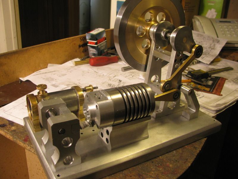
And here we have a very dainty cylinder head, complete with sparkplug. Everything seems to fit okay, all the bolts went in and caught threads, and I guess thats the important part!!!
I managed to find a North American source for the timing belt and pulleys, and ordered them today. When they get here I will post a picture of them along with the cost and the address of where I got them.
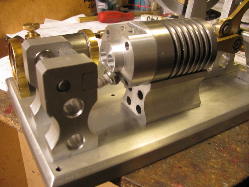
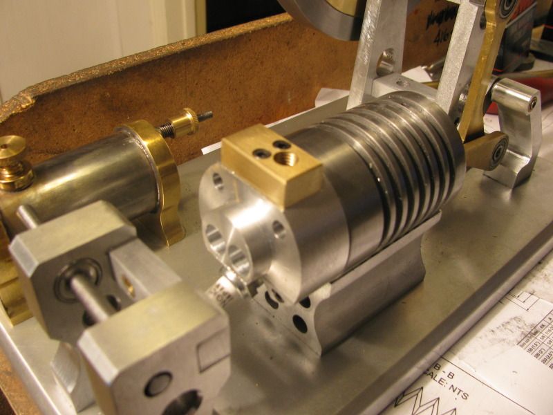
Bit by bit I carry on with this build. I'm down to the point now where I am building small parts in order to have something to bolt even smaller parts onto!!! Tonight after dinner I managed to whittle out an intake/exhaust manifold and bolt it to the cylinder head I finished this morning.


")