Brian builds Atkinson Engine

Home Model Engine Machinist Forum

Help Support Home Model Engine Machinist Forum:

This site may earn a commission from merchant affiliate links, including eBay, Amazon, and others.
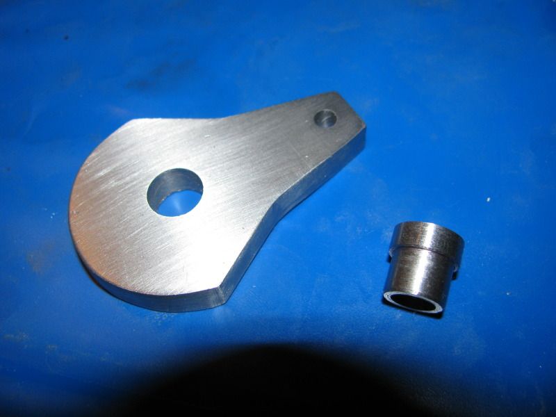
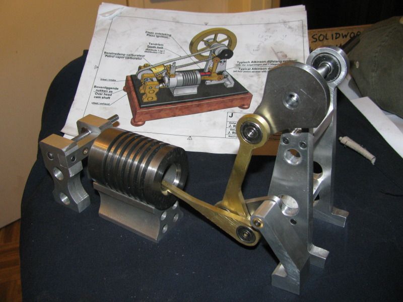
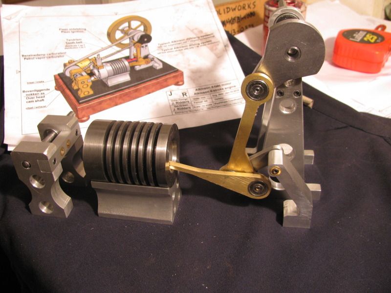
It's nice to show that not everything has to be done on the mill. K point for that :) (We can still call them that if we want to can't we?)

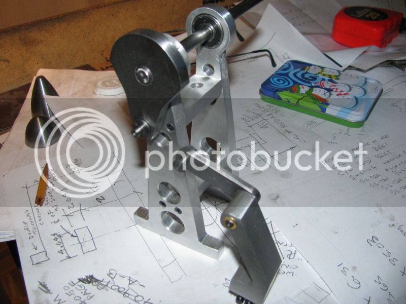
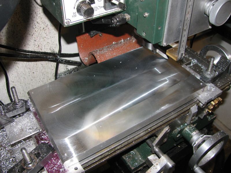
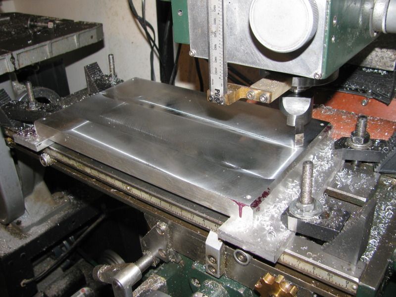
That is a beast of a belt sander you have built yourself there. I envious!
 
Brian, I don't post much, I am always looking, reading and trying to learn.

I really enjoy your build logs and really learn a lot. You are an outstanding machinist as well as your CAD and Modeling skills.

Keep up the great work and enjoy.

Watching from the sideline.

Ray
 
Hi Brian,

Thanks for taking the time to post all these details. As a novice, this is a great way to learn. I can't tell you how many times I've said "Oh, that's how you'd do it" while reading your posts.

Shawn
 
Brian,


Remember that most tooling speed charts are designed to maximize production and minimize tool wear at the same time. So long as you don't go too fast and burn a tool, I'd look for finish quality and accuracy more than anything.

Alan

Hello misters,

in France there is one book for students machining (formula handy pocket), referred to as "Form ADAM" I think it is possible to find it on Amazon for a few Euros, it is filled with original tables are represented with good cutting speeds, it is not made for burn the Carbide Tools, but above all to master the use!

There are of course all threads Metric and Imperial, Abaques, etc...
Then in industry, it makes fun of the carbide pad "burn", what matters is performance, but we're not there, we are not especially eager to screw up our equipment, for me anyway.

Congratulations to you Brian, I will follow your thread of discussing on construction engine to the end !!! ;)

cordially
J-M​
 
Another way to drill holes like that without a sacrificial piece underneath is to raise the stock from the table (123 blocks are good for this).
 
This shows the hub turned as a seperate peice, and press fitted into the crank throw. This assembly gets silver soldered to the end of the flywheel shaft, so for now I will leave all the silver soldering to be done at the same time.
HUBFORCRANKTHROW001.jpg

HUBFORCRANKTHROW003.jpg
 
Green loctite is excellent for fixing shafts into holes, and a lot quicker/easier than SS. Give it a try.

The parts can be separated by application of heat (> 500 degrees).
 
I haven't ran off, nor abandoned things. Suddenly out of nowhere I have a bunch of old customers wanting "immediate" attention for their customers who "Can't wait"!!! That means I don't have a lot of machining time right now, and I firmly believe in "Making Hay while the sun shines"!! I try to make at least one engine part per day, and as there are lots of stubby little shafts and levers on this engine, I can generally find some 1/2 or 1 hour job. Every thing seems to be working out well, and MAYBE I can start assembling some of the larger parts next week.
ITSYBITSY-3001.jpg
 
Yea Brian we are right here with you. Great work so far.

Don
 
And the beat goes on----. Found an hour this afternoon to machine the "Central Drive Link" from 3/16" brass.---Nothing special there, so no in process pics. I tried to capture the con-rod layout in this pic but it didn't show up very well. I'll get up in the morning and machine that out. I did have one interesting thing happen while machining the "Central Drive Link".--I made a stupid math error, and bored the one end (which is supposed to be exactly 16mm to suit the roller bearing) out to about .008" oversize. I didn't want to scrap the part, but the bearing has to be a tight fit in the hole at each end and get Loctited in place. How to shrink a hole???---Well, if you can make a shaft a few thou larger in diameter by knurling it---should work on a hole too. How do you knurl a hole?--Well, I can't, but its simply a matter of "upsetting" the metal. I took my automatic spring loaded punch and centerpunched a spot every 3/32" or so around the inside circumferance of the hole in the brass. It worked like a charm!! The bearing is now a "snug" fit into the hole. I have to silver solder a stub shaft into that small hole that you see, and then I will Loctite the roller bearings into each end.
conrod003.jpg
 
Brian, thanks for the "How to" to shrink a hole. It seems that I am building more experience in fixing up fopars than doing it right first time!

Brian
 
Aha, by God!!! Its beginning to look like the drawing!! I got up this morning and whittled out the connecting rod and did a bit of silver soldering. Then realization hit me---Hey--I've got enough parts to dummy up an assembly. I always get a thrill when things get to this stage.----Brian
FIRSTASSEMBLY003.jpg
 
For the last two years I have been trying to get better pictures. I am a complete camera novice, and I have had the recurring problem that if I use the flash to take pictures, I get "white out" spots all over the picture. If I don't use the flash, the pictures are too dark to see. I have to take 8 pictures to get one good enough to post. Today I went downtown and spent $110 for a diffuse light reflector, bulb, and tripod stand. This is the same picture I posted this morning, using the new equipment and no flash.
CAMERAHELP001.jpg
 
I thought that umbrella would help. The color is much warmer with your new setup.

You got a lot of good advice on your other thread about how to go even further with this if you want. It takes lighting from multiple angles to eliminate all the shadows. Setting up the lighting to get the perfect shot can take as long as making the part so there is definitely a line of diminishing returns.

I think what you have is great.
 
Wow, Brian, I don't check in for a few days and you darn near got the engine finished. Wish I had your energy!

Chuck
 
Wow, Brian, I don't check in for a few days and you darn near got the engine finished. Wish I had your energy!

Chuck
I'm not really knocking myself out on this one Chuck. Just fitting it in between real work and summer vacationing with our granddaughters.
 
Here we have todays adventure in flycutting. The results are much, much better since I "trammed" the head of my milling machine. I am using a HSS cutter which I ground.This baseplate presents a fair challenge, because it is both longer and wider than the travel of my mill in x and y planes. I have drilled and tapped a #10-24 thread in the each corner of the baseplate, and to these have bolted some "footplates" to clamp it to the mill table. After I am finished flycutting, I will remove the footplates and drill the four corner holes out to 3/16" diameter to become hold down bolt holes for the base. The flycut finish is good, but not "cosmetic grade" in my opinion. However, the top surface of the plate is now truly flat, and I will give it a bit of attention with my "jitterbug" sander and some 180 grit paper to remove any remaining swirl marks. This base is 3/4" thick instead of the 10mm (3/8") material called for by Jan Ridder, because after seeing videos of this engine running, and seeing how the out of balance engine wants to jump around, I decided heavier was better, to help dampen some of the vibrations.
FLYCUTTING003.jpg

FLYCUTTING002.jpg

FLYCUTTING001.jpg
 
Some beautiful work here Brian. And, a very intriguing engine design. I look forward to your continued progress.

A question though, if you will. What is the rest of the polishing process after you run the 180 grit paper over the surface of the base plate? 180 seems awfully rough to me. I would think it would create a lot of deeper scratches in the surface. But, I must admit I'm more familiar with sanding wood than I am with steel.

Todd
SilverSanJuan--It all depends on how perfect a finish you want. I don't want it to shine like a mirror----Just be a uniform aluminum grey with no visible swirl marks from the flycutting. If the 180 grit doesn't bring it up good enough, I will use some 320 paper. after that, if you want it more mirrorlike, its time to get out the 8" polishing buff on a stationary grinder arbor and work through succesively finer grits polishing of compound.
 

Latest posts

Back
Top