Anybody want to guess---

Home Model Engine Machinist Forum

Help Support Home Model Engine Machinist Forum:

This site may earn a commission from merchant affiliate links, including eBay, Amazon, and others.
***********OFFICIAL VACUUM FILLER*******************

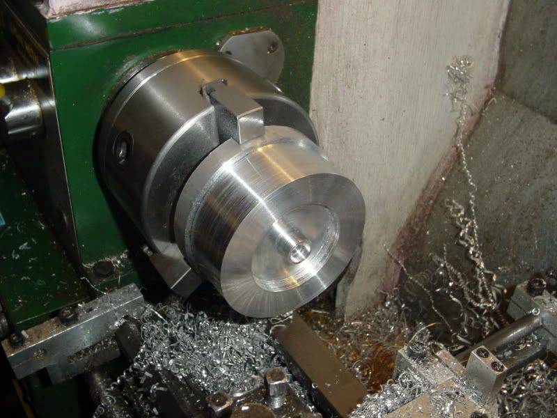
Cylinder is looking good. What are your plans for the rings?
 
Had to stop and watch "60 Minutes" with my good wife----Now, where was I----oh yes, what did I do the rest of the day.---Wifey and I took a drive around the area to see all the flooding that occurs every spring when we get a week of warm weather in March, then back to the machine shop.---To make the "perfect Piston"!!! Well, maybe not perfect, but it turned out nice. Thats why I wanted to hone the cylinder first, so that I could make the piston a "perfect fit", ot at least as perfect a fit as I am capable of producing. I set a piece of 1" aluminum rod up in the lathe, and "snuck up on it" untill the cylinder would just slide over the end with a little oil. Then went ahead and used pretty well all the conventional steps one would use to make a piston. Since I favour mostly #5-40 and #10-24 socket head capscrews, I changed one dimension on the Webster plans (you can see it circled up on the drawing--changed the hole spacing from 0.625 to 0.550 to let me use a pair of #5-40 shcs to retain the wrist pin). Piston rings??? Well you may ask. The original poster on this forum admitted to using a Viton o-ring in his Webster, and Chuck says that he used an o-ring of unknown origin on his Plumbing Parts engine, so thats what I am going to use. Right now their is no ring groove shown on the piston, because I don't know exactly what size to make it yet. Their is a business in Barrie called "Hercules O-ring" where I bum all my O-ring drive belts from, and they can supply me with the dimensional specifications and with the proper viton o-ring this week. I am their only customer who "buys" one o-ring every 3 or 4 months, so I generally take whatever engine I am currently building over with me, give them a little "Show and tell" demonstration and a $2 donation to their coffee fund and come away with whatever o-ring I need. ::) ::)--In the second picture down you can see the "oil tube" which supposedly aligns itself with the drip oiler in the cylinder on every stroke to supply oil to the wrist pin bearings.
piston008.jpg

piston010.jpg

piston011.jpg
 
Good going Brian ;D

I've been sitting quietly in the wings following along, like you have noticed, so I'll chirp up now-and-then!

Kind regards, Arnold
 
Here is a method I have used to hold a ball. Put two pieces of brass or aluminum in the vise with a piece of heavy paper between them. With a bit of the correct diameter, drill a hole centered on the parting line to a depth of just over 1/2 the diameter of the ball. Take the paper out, insert the ball, clamp down, viola!

Jerry
 
cfellows said:
Yes and no. From a performance perspective, it's outstanding. Easy to adjust the air mixer, starts first time, every time, and never misses a lick. However... there's no throttle adjustment, so the engine takes off and runs full tilt unless you have it governed. You can adjust the speed somewhat by making the mixture run rich, but it also makes the engine run uneven. So, it needs some kind of butterfly or other adjustable restrictor between the engine and the air mixer.

Chuck

Why couldn't you just use a common 1/4" ball valve---The kind where a turn of 90 degrees goes from "wide open" to "totally closed"??
 
Great fun, entertainment and learning watching your build Brian. :) :) :)

Keep at it

Jeff
 
Brian I see that the build proceeds well, very nice job

I was thinking to buy a tool to hone the cylinders just some days ago, exactly like the one that you have showed

I don't have any cylinder to hone at present, it would be a purchase just "in case" for the future
but I don't wish that it could stay in a drawer for 30 years :big:

purchase delayed ;D
 
Tomorrow I think I'm going to treat myself---to a piece of 4" diameter brass about 1 1/2" long, to make a flywheel for this Webster build. I just shipped off a disc with 120 hours of very intensive automation design for a pharmaceutical company, and a darn nice invoice with it. And tomorrow I start redesigning a machine for grinding cement core samples for laboratory inspection. I love it when the contracts come back to back like this---It takes all the guilt out of buying things that I don't really need. ;D ;D
 
Ah---The best layed plans of mice and men----I went down to my metal suppliers to pick up a 2" length of 4" diameter brass to make a flywheel. Upon arriving, it was disclosed to me that 4" diameter round brass is $230 a linear foot---and they didn't have any!!!! So, Plan B was created "On the spot" and I bought a 2" length of 4" diameter aluminum instead---and a 12" length of 1/2" diameter brass--And a piece of 1" x 3/8" brass bar stock x 12" long. For the grand sum of $40.00 The plan now is to make an aluminum flywheel with 1/2" diameter brass "inserts" around the perimeter of the flywheel at every 36 degrees. The piece of bar stock is destined to become the lever which operates the intake valve.
FLYWHEELMATERIAL001.jpg

FLYWHEELWITHPLUGS.jpg
 
The price of brass is really ridiculous! Cast iron @ $65 a foot is a reasonable alternative. 12L14 @ $75 a foot is also not too bad.

If the aluminum flywheel turns out to be too light, you could always press a short length of steel tubing (or brass if you can find it) over the outer rim to add weight.

Chuck
 
Brass inserts will make the flywheel real spiffy Brian.

adj. spiff·i·er, spiff·i·est. Smart in appearance or dress; stylish. tr.v. spiff·ied, spiff·y·ing, spiff·ies. To make attractive, stylish, or up-to-date
 
cfellows said:
The price of brass is really ridiculous! Cast iron @ $65 a foot is a reasonable alternative. 12L14 @ $75 a foot is also not too bad.

If the aluminum flywheel turns out to be too light, you could always press a short length of steel tubing (or brass if you can find it) over the outer rim to add weight.

Chuck
I don't really think it will be too light. I have seen videos of the Webster running with just the plain aluminum flywheel. I think if I add 10 brass inserts as shown in the CAD model, I should be okay for weight.
 
cfellows said:
The price of brass is really ridiculous! Cast iron @ $65 a foot is a reasonable alternative. 12L14 @ $75 a foot is also not too bad.

Chuck

You might check ebay. Sometimes you can find brass cutoffs for reasonable prices.
 
We're making flywheel progress this afternoon, but my Lord, what a swarf monster!!!! The o.d. is finished, the recess in the side that shows, the 5/16" thru-hole is reamed, and the 0.500" counterbore is in for the cam gear. I swear this thing creates swarf on the ratio of 100:1. Something I have discovered here also. I always have trouble putting the recess in the sides of a flywheel---its just a miserable area to get at. A couple of months ago when I was making the "Elmers 33--Kind of" engine, I needed a cutting tool to reach into a difficult area. I had a parting off tool that was a bit too large for my lathe (I purchased a smaller one)---I ground this dreadfull daggerous point on it, and its just the cats meow for doing the flywheel recess. I turn the tool so its at 90 degrees to the flat face of the flywheel, and take a seried of plunge cuts. This works far better than any other way I have tried for this task. I have included a couple of shots of this formidable looking tool.---try it---You'll like it!!!
FLYWHEELMACHINING004.jpg

FLYWHEELMACHINING005.jpg

FLYWHEELMACHINING006.jpg
 
Brian
Looks like the right kind of tool for the job.
Regards
Ernie J
 
All things considered, that went very well!!! I have my little shop knee deep in aluminum swarf, but I'm pleased with the way the flywheel turned out. I left an extra 1/16" of material on both sides of the main body, so that after I have drilled it and loctited the 10 brass plugs into place, I can finish turn both sides "to size" and hopefully a nice finish. I was looking at the design drawing, wondering why I didn't see any set screws in the flywheel. After reading a bit more in the instruction sheet, I see that the person who originally designed this Webster calls for the flywheel to be positioned correctly, then cross drill the flywheel and the crankshaft together for a 3/32" roll pin. I guess that must work, because he gives a link to a web page full of succesfully running Webster engines-----Its just that I feel a bit ginchy about crossdrilling the flywheel and crankshaft.--I mean, its so irrevocable!!!! If you don't get it right the first time, I guess you have to make a new crankshaft!!!!
FLYWHEELBEFOREBRASSPLUGS001.jpg

FLYWHEELBEFOREBRASSPLUGS002.jpg
 
Did he drill the roll pin hole at an angle or did he go through the rim to get to the hub?

Chuck
 
cfellows said:
Did he drill the roll pin hole at an angle or did he go through the rim to get to the hub?

Chuck.

Chuck.
Next time I will be building the Webster I will make the flywheel with a taperlock. Why because I know :big:
I had a real backfire on one of the first startups, resulting the rollpin sheared :'(
Brian: it's not to late to make a taperlock for the flywheel methink. And it is so much easyer to set up the exh.valve timing.
Best Regards
CS
 
This is about as good as it gets, in my shop. I didn't use a rotary table to drill these 14 holes. I sat the flywheel on top of a piece of "safrificial" aluminum plate, clamped it down to my mill table, and drilled all the holes using "ordinate" dimensions and the feed dials on my mill table---(I reamed the 10 holes in the rim). And if you have ever drilled a flywheel like this, I don't have to tell you how long it took me, or how much my back hurt from standing there untill I was finished!!! Now I'm off to cut 10 pieces of 1/2" diameter brass to loctite into the 10 holes around the rim.
FLYWHEELDRILLED001.jpg
 

Latest posts

Back
Top