Anybody want to guess---

Home Model Engine Machinist Forum

Help Support Home Model Engine Machinist Forum:

This site may earn a commission from merchant affiliate links, including eBay, Amazon, and others.
Hi Brian: That is a nice project you have going. I am interested in watching your progress. I never had any experence at computer drawings. Yours are a work of art. Good luck with your engine and if there is anything I can share with you I will be happy to. Jack B
 
Today I finished the baseplate---and Son of a Gun--It all bolts together!!! I didn't put the cut out in the baseplate that the plans show, because I want to mount the fuel tank in the area where the plans call to be cut away. Actually---The plans are different than the pictures of the finished engine in the post where I copied the engine plans from. I still lay out the hole positions as a "check", but I have got pretty good at dialing in all my hole positions using an edge finder and the feed dials on the X and Y axis of my mill. And in case you were wondering----Those humungous hypodermic needles in the background are a customers part that I am designing some material handling automation for. Apparently they are filled with some type of antibiotic cream that is used by veterinarians.
baseplateassembled001.jpg
.
baseplateassembled002.jpg
 
Brian; I also layout my holes but then use my DRO on the x and y axis with an edge finder. Sometimes (like today) they don't match and I catch the mistake before I drill the hole. I think it is a good practice to do it both ways and force measuring twice.

Have you decided on a carb yet? I am thinking about Chucks vapor system.
 
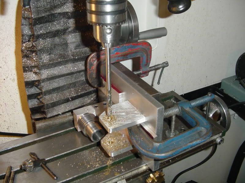
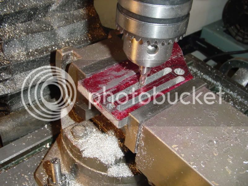
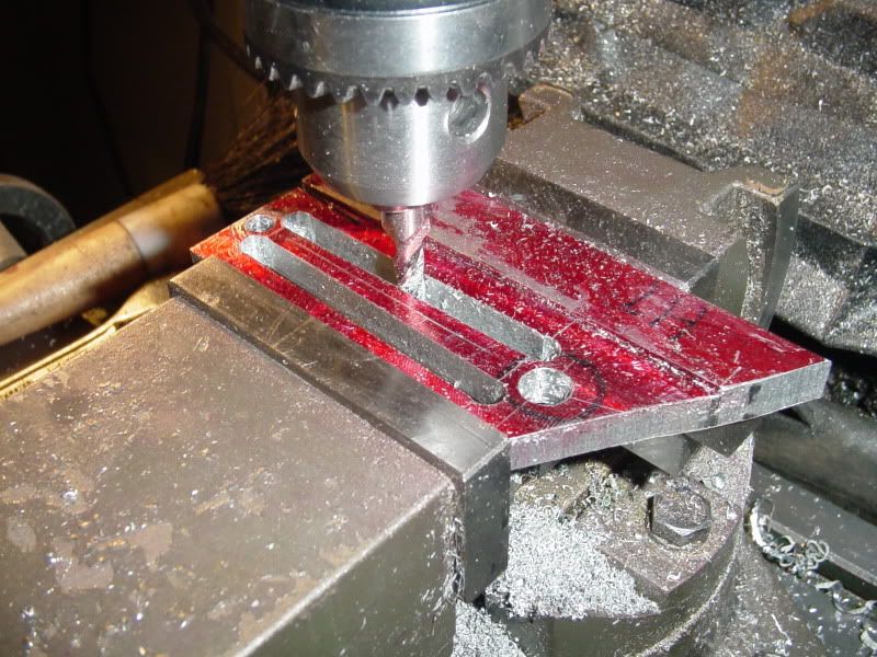
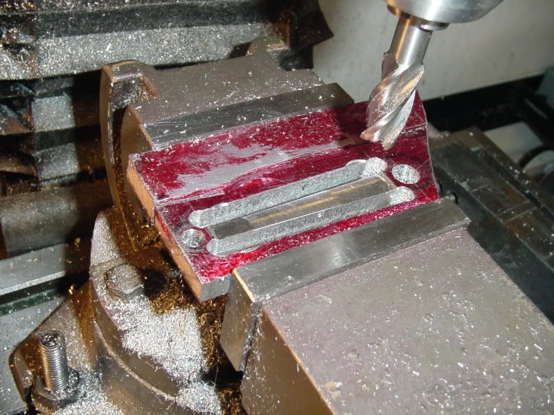
I'd like to add my thoughts about laying out the holes in that piece of plate. The designer (who seems to have done a very good job) layed out the holes in his drawing, looking at the side of the plate opposite to where the drilling actually takes place. This means that when I (this time the machinist) go to make that plate, I have to visualise the hole pattern in "reverse" to drill the holes correctly. It wouldn't matter if the holes were plain holes---they could then be layed out and drilled exactly as per the drawing. The fact that they are counterbored holes is the fact that makes it necessary to work from the "reverse" side of the plate. I like to drill the hole, and then immediately put in the counterbore tool without changing any of my offsets, put in the counterbore, and then move on to the next hole, and so on. This makes for a lot of changing back and forth between the drill and the counterboring tool. Probably this method would be discouraged in any kind of "production" machine shop, because of the time it takes, but for me, time is far cheaper than the hassle of drilling all the holes first, then resetting everything to put the counterbores in afterwords. I find this "reverse" layout very difficult. I know that I am guilty of the same type of thing in some of the drawings I make, and sometimes there is simply no "good" way of avoiding that.----Brian
 
Black85vette---I don't have the faintest idea of what to do about a carburetor. I have never built an i.c. engine before, and I can't help but think that a small carb off of some R.C. engine would be terribly expensive. (I don't know this for a fact.) I like Chucks vapour system, but I'm not certain that he ever got it to actually work to his satisfaction.
 
Hi Brian,

Just found this thread, I will be watching this unfold - I like the webster. I am yet to get into the world of I.C.s but it is something I aspire to do next.

Good work :bow:

Nick
 
I didn't care for the look of the rather plain crankshaft "throw" in the original plan, so I did a little creative whittling and made one which incorporates a counterbalance----
CRANKTHROW001.jpg
 
nice touch with the crank
should make balancing easer
as long as mine ran I was happy when i did mine lol
cheers Pete
 
Brian Rupnow said:
A little time on the mill cleaning up edges---And Voila'--A couple more parts for my Webster. Thats enough playing machinist for this weekend.
webstersideframes005.jpg

Sorry to quote a picture, but I wondered how you manage to round off corners like that?
 
I'm getting very close to having a crankshaft here. All thats left is some creative silver soldering. I had to go and buy a 5/16" reamer, but thats okay.--just another one to add to my ever growing collection. Maybe on the weekend I'll have time to make the crankshaft bushings.
CRANKSHAFTPRE-ASSEMBLY001.jpg

CRANKSHAFTPRE-ASSEMBLY002.jpg
 
Chuck--So whats the verdict on your adaptation of Jan Ridders "fume" carburetor? Are you 100% happy with it?-Would you recomend that I go that route for my first internal combustion engine. If there is something better, what do you think it is, and do you have any idea what they cost. I am an absolute "babe in the woods" when it comes to this small an induction system.---Brian
 
This afternoon I got held up waiting for some information on my "real job", so I put the time to good use by finishing the silver soldering on the crakshaft, and making the brass "main bearings".
MAINBEARINGS010.jpg

MAINBEARINGS009.jpg

MAINBEARINGS008.jpg

MAINBEARINGS007.jpg

 
The plans for the Webster engine call for an aluminum connecting rod with bronze or brass bushings. Is there any good reason not to just make the whole connecting rod out of brass, and not use bushings. If this was an engine being called on to do some actual work, I realize that strength could be an issue, but an engine that is only used for demonstration---??????????
 
Brian,

The only concern I would have is the extra weight from the brass might cause a vibration problem. My hit n miss engine has an aluminum connecting rod riding directly on a steel crank and I've never had a problem. Just keep it oiled and it doesn't seem to wear much.

Chuck
 
This is my set-up for "in-line" reaming. I have a big old angle plate that I bought when I bought the milling machine. I bolt it to the mill table, clamp the engine base to the angle plate, then use a piece of 1/4" cold rolled in the mill chuck to locate the "center" of the bushing---(thats why I reamed the bushings when I was making them.) Then I lock the table position, swap out the cold rolled for the proper size drill and drill through both bushings in one set-up, then put in the 5/16" reamer and ream both bushings in the same set-up. This may be a bit unorthodox, but I have used this method on a number of small engines now, and it works very well.
IN-LINEREAMING001.jpg
 
Brian: You got me excited about this one. Yours is looking great (no surprise there). I have ordered the material for the cylinder and am getting twice as much as I need so when I screw up the first one I won't have to wait for another shipment. ;D I did get a nice surprise when I ordered. I selected "pick up at local store" because they don't charge for shipping that way. Got an email that said they didn't have my material in stock locally but they were shipping from St Louis to my house at no extra charge. Sweet!

Like your set up for boring. I will give that a go. I have been drilling and boring the two sides clamped together rather than in their proper positions.

Chuck: I have the same question Brian does; are you satisfied with the fume tank / carb? Will it work for this engine?
 
I tried to start on my flywheel this morning, but that end from a 4" diameter shaft I picked up last week for $2 is harder than the devils horn!!! Even with carbides my little lathe was squealing and smoking, so I quit. I don't want to wreck my machinery---I called down to my metal supplier and he can sell me a 4" diameter piece of brass x 1 1/2" long for $45, so I may use that instead. Since I had the rest of the day to play in my shop, I decided to make the connecting rod. Remember last week when I had to mill down a piece of 3/8" aluminum to get some 5/16" thick to build the webster bearing stands---Well the Lord must love me, because I found a left over piece of it just big enough to make my con rod. I layed out the centers, and also layed out the center of the four 1/4" holes that create the 1/8"radii where the tapered center meets the round ends of the rod. I set it up in my "Tilt a Whirl" vice, drilled all the holes, and reamed the two which will get bushings. Then, having calculated the angle of taper on the connecting rod center section, I offset my vice 1.5 degrees and milled from hole to hole. This worked out great.
CONROD001.jpg

CONROD002.jpg
 

Latest posts

Back
Top