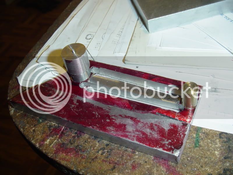
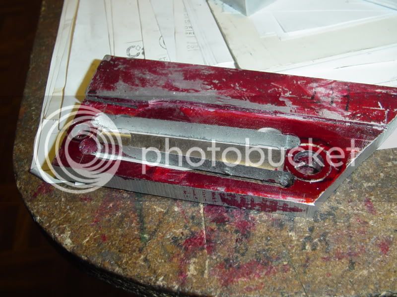
I then made up a couple of round plugs with stepped diameters---the smaller diameter turned to fit in the reamed hole in the end of the rod, and the larger diameter to match the large diameter at each end of the rod.--I inserted the plugs and used them to trace around with my scriber, so that I would be able to clearly see the finished sizes when the plugs were removed.