Mosey
Well-Known Member
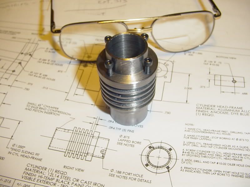
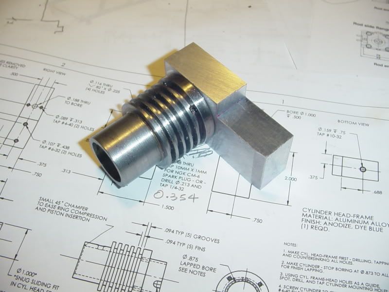
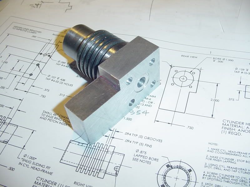
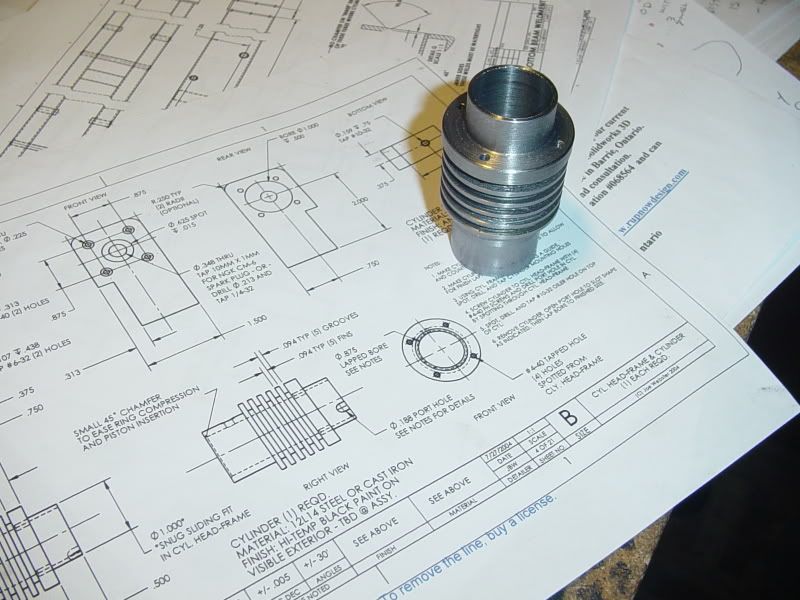
Brian Rupnow said:This evening I discovered the first "caveat" for anyone building the Webster engine. The four tapped holes that hold the cylinder to the "Cylinder Head-Frame". I used #5-40 threads instead of the #4-40 called for on the plans (only because I have a box full of #5-40 shcs). And here's the rub----If you only drill through the 1/4" mounting flange, and not through the first cooling fin, (for cosmetic purposes), then you can't get the threads all the way through with a normal tap, because, of course, the end of the tap hits the first cooling fin. So---I'm going to have to buy a #5-40 bottoming tap. Every time I build anything, I end up having to buy more tooling. I was afraid of putting in a tapered bore, as the cylinder is 2 1/2" long, so this morning while I was out, I bought a 27/32" drill and a 7/8" chucking reamer. That shot my budget to the tune of $82.00. Now I have to buy a bottoming tap. #@$%!!!
As I see it, every time I go to make something, I get the opportunity to buy more tooling!! Whoopee! Almost as good as getting to buy another machine.