Hi,
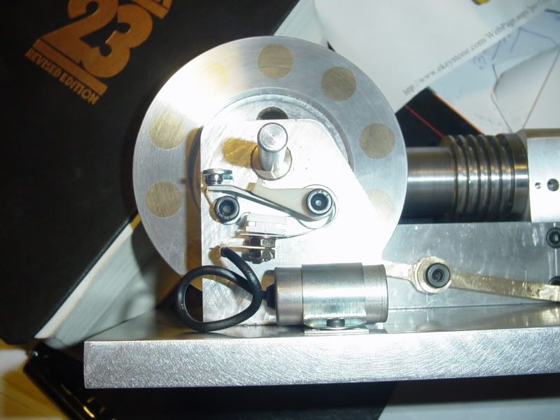
Looks like you're coming along on your beautiful Webster quite nicely! I was looking at your picture of the rocker arm being machined and I think I see an endmill being used in a drill chuck. Bear in mind drill chucks are designed for movement in the Z axis only. No side movements for these. If you're side milling, the chuck can work its way off the taper and fall off. A real safety issue to be aware of, no one likes a loose spinning chuck. You'll have strength and runout issues in a drill chuck also. Not trying to be a jerk here, just wanted you to be aware.
Dave
") I will do it that way.
I will do it that way.