Potty Simpson and Shipton Short Stroke Engine

Home Model Engine Machinist Forum

Help Support Home Model Engine Machinist Forum:

This site may earn a commission from merchant affiliate links, including eBay, Amazon, and others.
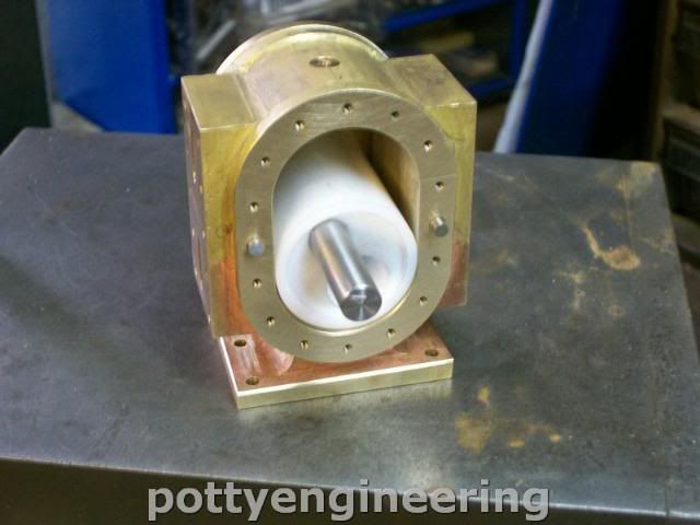
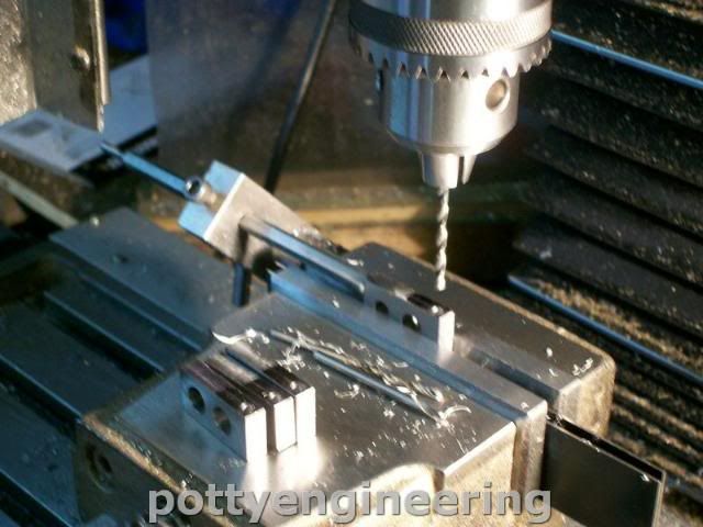
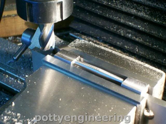
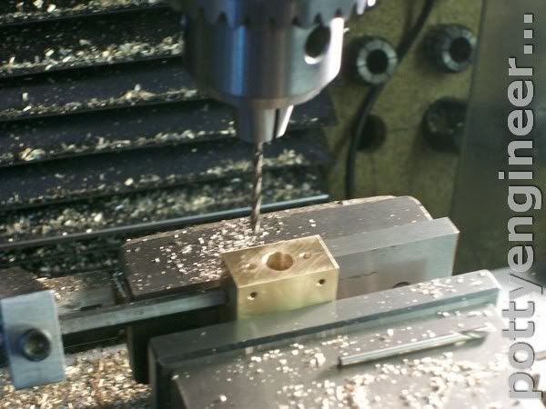
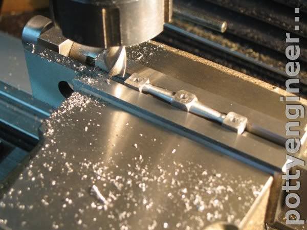
Got the stream chest finished off, today.

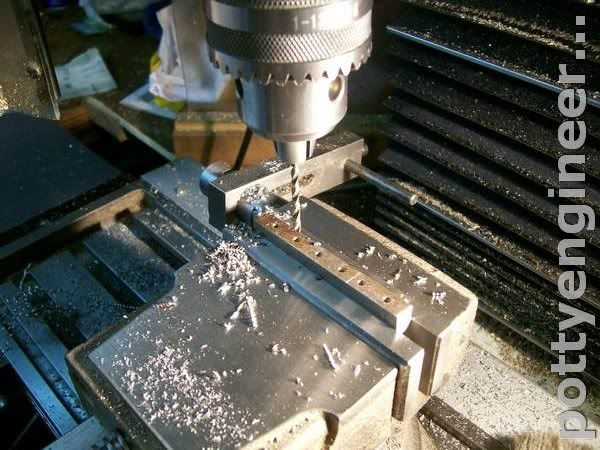
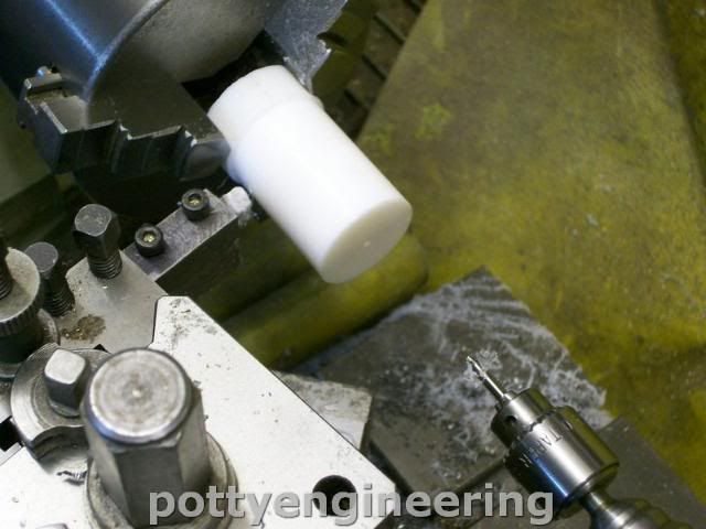
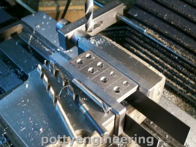
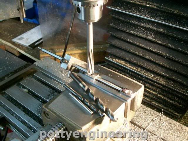
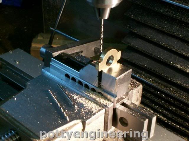
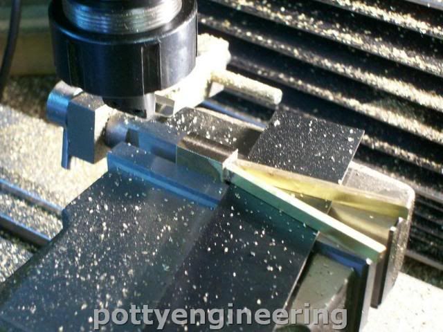
Drilling the holes for the sealing gland.

131_1250.jpg


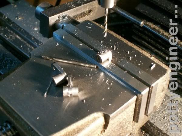
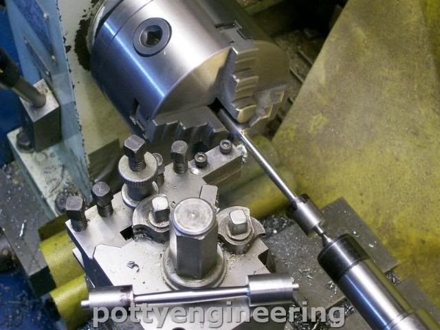
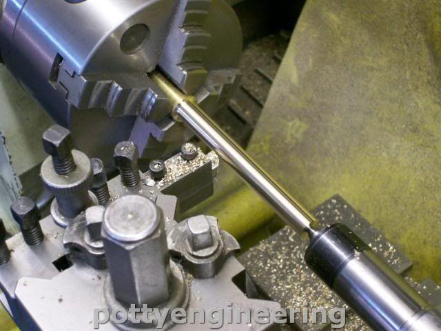
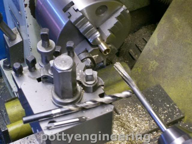
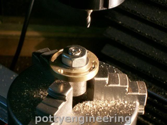
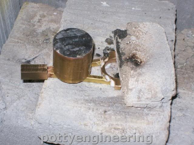
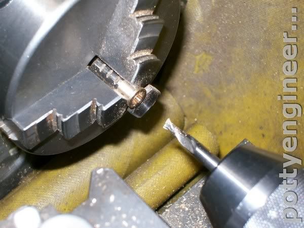
Next up the little top hat to take the graphite cord.

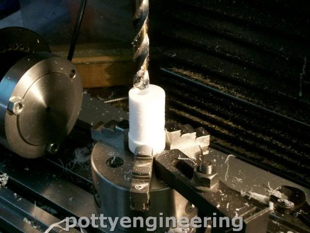
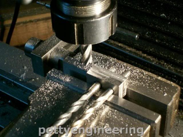
Turned the OD and reamed through 3mm parted off flipped it round then used a slot drill to cut the flat bottom hole.

131_1252.jpg


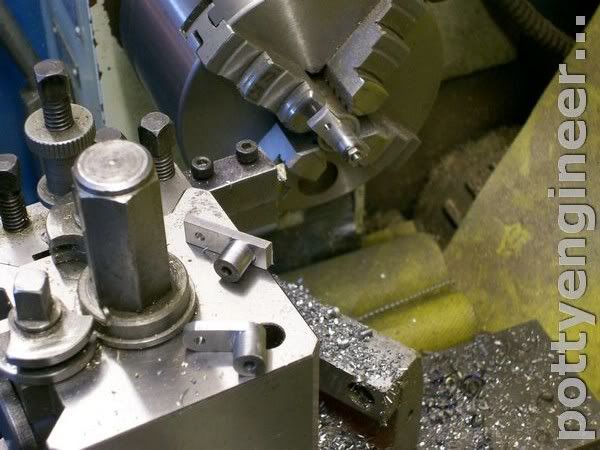
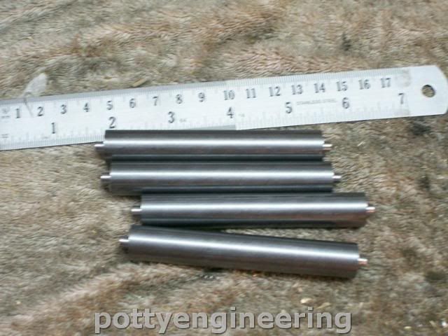
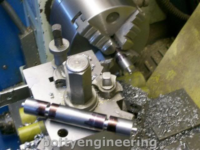
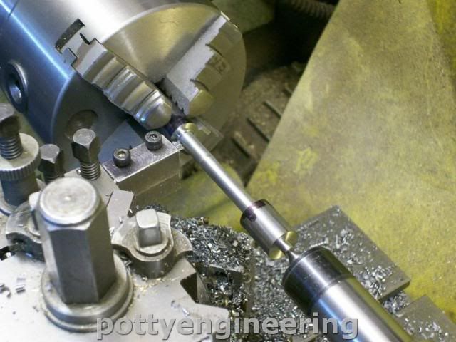
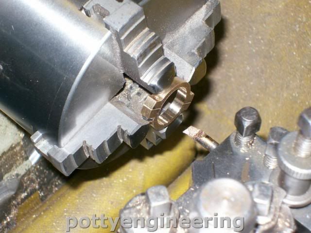
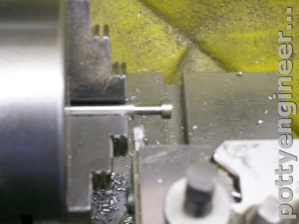
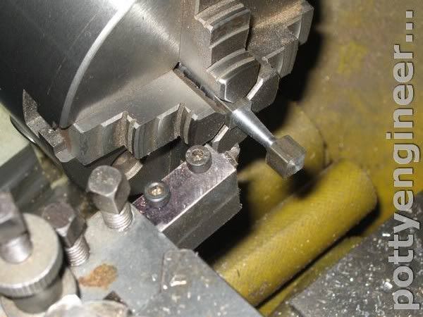
Then turned up the spool valve from some silver steel bar,
Drill and tap and acuratly turn the gap and over all length as these are important to the valve timing.

131_1255.jpg


Camera went flat at this stage, and couldn't be arsed to get the spare out of the house.

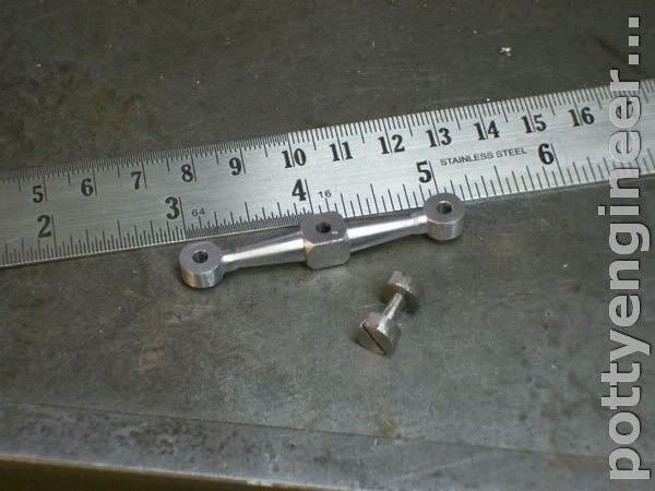
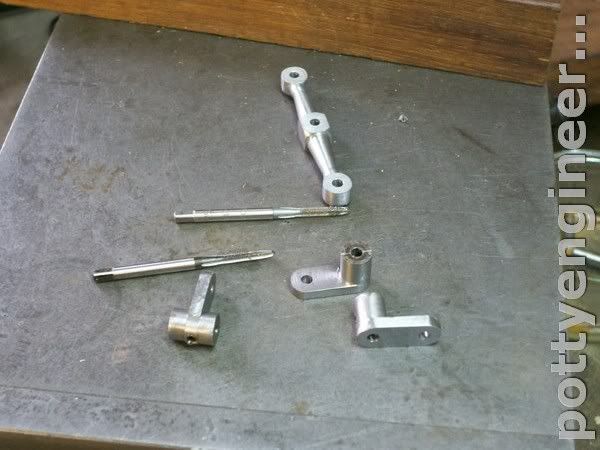
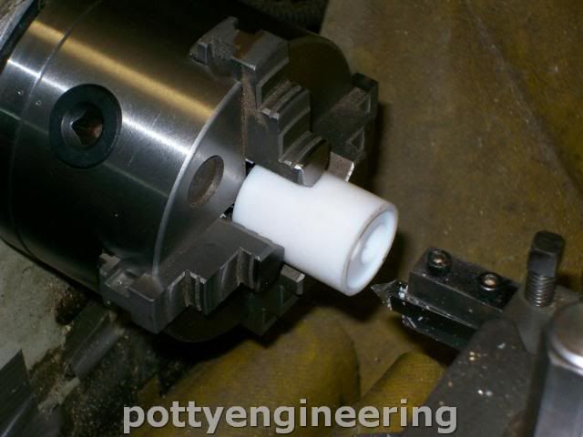
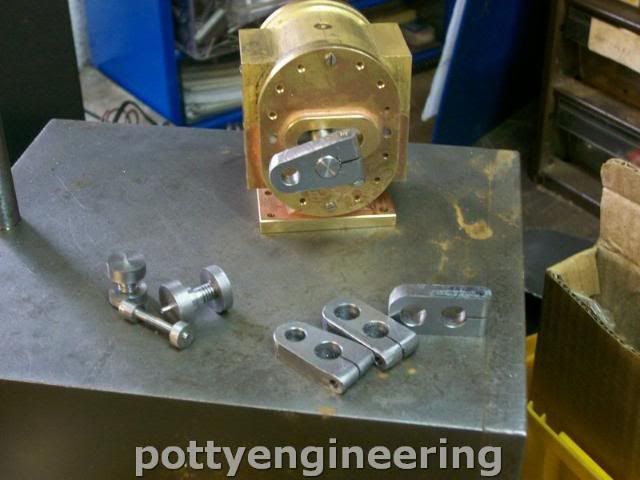
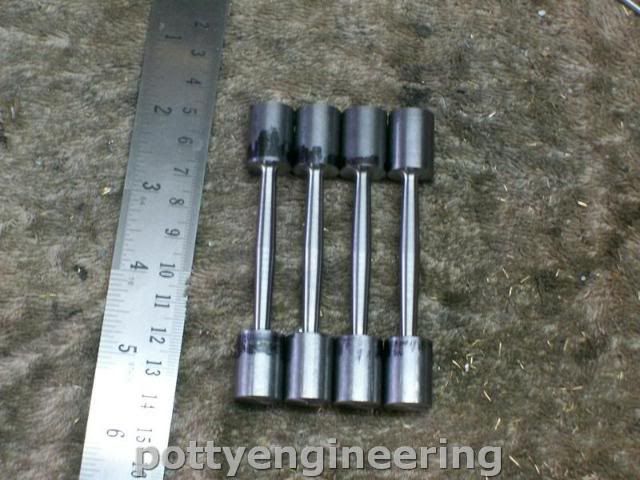
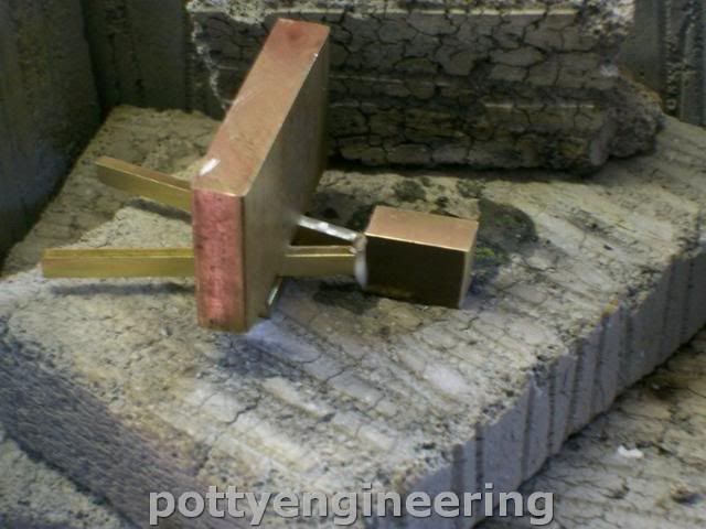
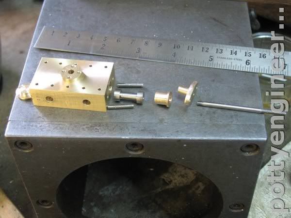
Finished of the rest of the bits for the gland, this is how they all fit togethere

IMG_3576.jpg


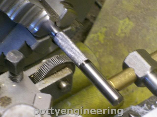
Then onto the valve cross head bar, made this from a bit of 1/4 square bar, so in the four jaw self centring chuck, rough out the steps.

IMG_3581.jpg


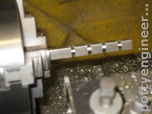
Then with a thin tool and with the compound slewed over 5 deg turn the taper bits.

IMG_3584.jpg


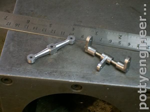
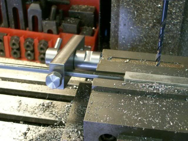
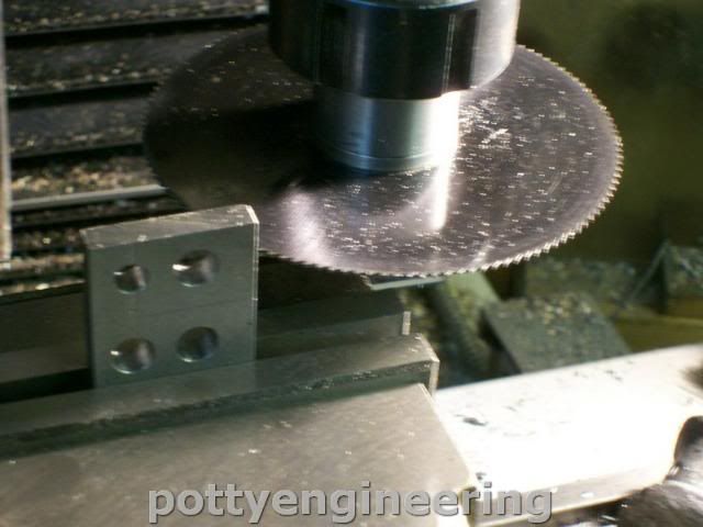
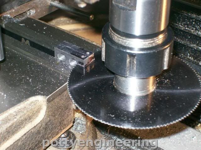
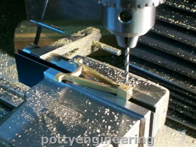
Over onto the mill and find the midle of the bar and drill though 3mm index to the outside bits and drill these through 3mm as well.

IMG_3588.jpg


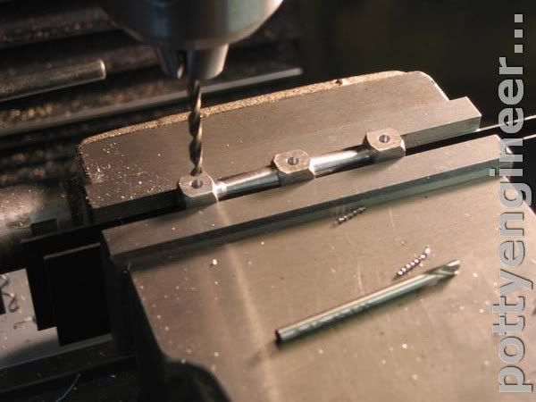
Then with an end mill thin the end bits out.

IMG_3591.jpg


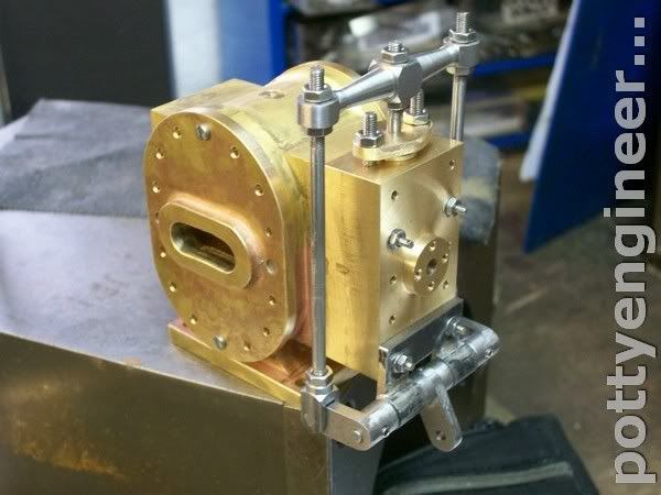
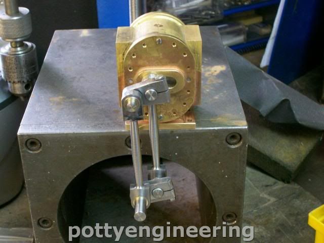
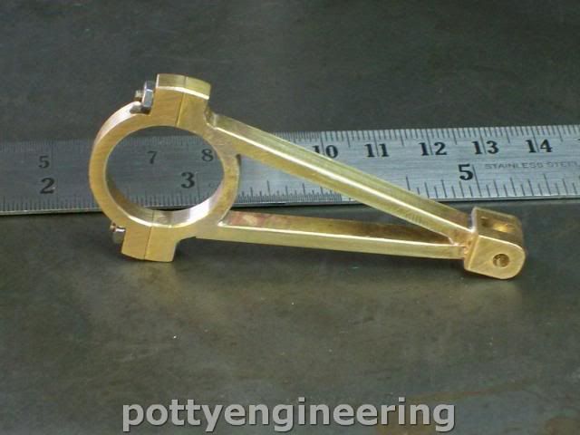
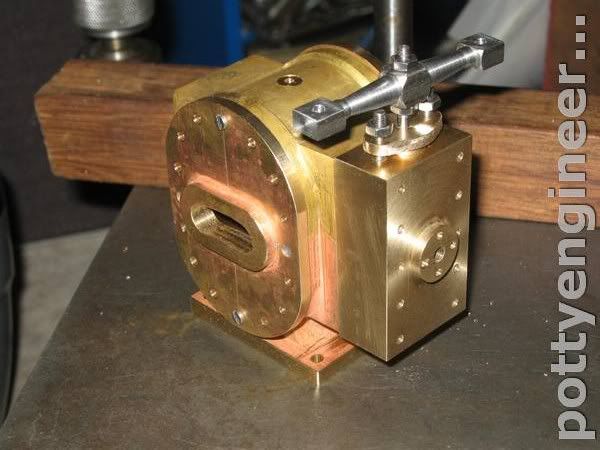
Time for an hows it looking.

IMG_3592.jpg


Stew
 
Thanks for your interest Ray/Danstir

Things will slow down over the next week as I'm on domestic duties :(

Decided the cross head would look better with the end bits rounded off so made a filing button and nibbled away with files, I think that looks better:-- less clumsy.

131_1259-1.jpg


Used the rest of the morning making the link bars.

First cut off a length of bar enough to make all three links, then drilled some pairs of 3mm holes 12.5mm apart, the DRO on the mill gets the pitch for each one very accurate.

131_1276.jpg


Cut each link from, then turn a 3mm mandrell on the lathe, bolted each link to it and faced it off to form the arm.

131_1277.jpg


With the same filing button finished the ends off, then drilled and tapped M2.5 for a grub screw.

131_1281.jpg


Job done

131_1282.jpg


131_1288.jpg


Stew

 
It looks obvious when you do it Stew, but I guess that is the mark of a true craftsman. :bow:

Jim
 
Nice work, and I really like all the photos.

You seem to make great use of a stop in your vise. It looks like a simple stop block, but it a couple photos it appears to be rotated and have a double stop.

Could you please show a photo of the stop itself and offer a few words on how it is used?
 
Decided the cross head would look better with the end bits rounded off so made a filing button and nibbled away with files, I think that looks better:-- less clumsy.


I absolutely agree!...nice!

Dave
 
Ron,

In all honesty, a good, rigid mill vice stop should be one of the first bits of extra tooling you should make. I made the mistake of using a mobile one for many years, but eventually I realised I needed something a little more permanent.

I showed how I made mine here. Very long winded in the beginning, but it might give you a few ideas, as it did for Stew.

http://madmodder.net/index.php?topic=1007.msg7615#msg7615

No need to go to the extremes that I did, but do take time to make it rigid and square.

John


Thanks for all your comments Guys

Ron:- I pinched the stop design from Bogs, he showed me his design on one of my visits to his shop, it's a little gold mine for ideas.

Stew
 
Hi Ron

I'm not at home at the moment, this is the best pic I've got, it shows the stop on my old vice.

100_1956.jpg


Hope it helps

Stew
 

Thanks Guys

Started back on the engine for a little while at least.

Finished off the rest of the linkage

131_1383.jpg


Made the piston today its a job I've been putting off don't know why I guess I just had a funny for doing it.
I liked the idea of making the piston out of PTFE, the main reason is its slippy plastic and quite soft, and I figgured that if I made it just a coulple of though longer than the cylinder it would act as a good air seal against the covers ??? we'll just have to see how it works out the bottom line is to change it for steel if it don't work out.

I used very sharply honed tools it cut like butter with a great finish.

131_1386.jpg


Set it up in the mill and drilled the off set holes.

131_1388.jpg


Back on the lathe and resessed the faces.

131_1395.jpg


Then parted off a length of 8mm silver steel (drill rod) and put a rough straight knurl into the middle.

131_1401.jpg


Sorry its such a crap pic

Then gently tapped the rod into the cylinder the straight knurl acting as splines to give it grip.

Mounted it back in the lathe a carfully skimmed the cylinder to width

The cylinder covers wern't sitting flat so gave them a bash wif me ammer, and a rub on emery cloth on a flat surface.

This is how it looks in the bore

131_1402.jpg


Stew
 
could you have a perspex end cover for the odd run to see it working ? :bow:

Peter
 
Hi Stew,

I've used teflon for piston rings on my launch engine, and it's held up nicely

I think that should work great!

Nice work!

Dave
 
HS93 said:
could you have a perspex end cover for the odd run to see it working ? :bow:

Peter

I've got one tucked away Peter.

Cheers Dave that good to know

Had a couple of sucessful days in the shop.

Made the crank webs, they are of the pinch clamp type so you can get them on and off due to the design of the engine.

First drill the holes 2 with 8mm crank pins 2 with 6 mm crank pins

131_1403-1.jpg


Cut off with slitting saw

131_1407.jpg


With two drill through the holes across top of vice, mill off so they are central, for the two cranks with the 6mm crank pin holes had to use a drill imm smaller

131_1408.jpg


Drill and tap and open up half with a clearance drill

131_1411.jpg


Cut the split.

131_1414.jpg


Then with filing buttons file to shape, they still need a bit of tidying up and a rub with emery, but her they are with the buttons

131_1415.jpg


Think they look a bit on the heavy side may thin them out a bit.

Next up the con rods the engine has four using 9/16 free cutting mild steel first cut off to length face them up so they are all the same and centre drill and turn up a lost centre.

131_1419.jpg


With a part off blade put a couple of grooves into them to show where to stop and to give some clearance to the turning tool.

131_1420.jpg


The with a running centre chew the meat out of the middle.

131_1421.jpg


Slew the compound over a couple of deg and with a radius tool form taper toward the chuck, swap it round and tune the other end to form the barrel.

131_1424.jpg


131_1425.jpg


Cut the centre pips off then over on the mill cut the flats.

131_1426.jpg


Called it a day at that and went for a brew and a snooze.

Stew
 
Finished off the con rods

Drilled and reamed

131_1427.jpg


Then turned up the bearings I needed eight of them I didn't want to P*** about to much, so turned a length of bar for a good fit in the con rod ends and parted off.

131_1428.jpg


I'm using my independat four jaw that chucks up very true, this allowed me to drill and ream right through the bar.

131_1429.jpg


Then it was just a matter of parting the bearings off to length, fitted into the con rod with a spot of bearing retainer.

A bit of work with filing buttons to shape the ends and this is they fit to the cylinder

131_1441.jpg


Things comming together well

Stew
 
"coming together well....." Boy, I'll say! You make fabricating oddball shaped pieces seem so effortless and easy, Stew. I like the overall lines of this engine, art deco-ish in a way. Whatever style it is, I LIKE IT! Thm: Carry on.

BC1
Jim
 
bearcar1 said:
"coming together well....." Boy, I'll say! You make fabricating oddball shaped pieces seem so effortless and easy, Stew. I like the overall lines of this engine, art deco-ish in a way. Whatever style it is, I LIKE IT! Thm: Carry on.

BC1
Jim

Thanks Jim you'll enjoy this next bit:----- I did ;D

Eccentric strap:- I've had it in mind to make the strap silimar to an eccentric on an 1850 ish beam engine I saw in a museum, it was a lovely cast iron job with a delicate latice work of circles, this will be too small to do the cirlces but I fancied doing something in that flavaour.

First part the strap end, cut off a sliver of brass 5mm wide drilled an hole up the middle and mounted it on a mandrel in the rotary tabel, and generate the strap end out.

131_1444.jpg


Then drill and tap M2.5

131_1450.jpg


Split it in half bolt it back together and grip it in the self centering four jaw and bore it out.

131_1458.jpg


I've spent ages thinking how to do the next part, I've had all sorts of complicated plans, in the end i decided to go the simplest way as i'm a bit of a simple bugger at heart.

So milled out a couple of 3*5mm wide strips of brass and with a big chunk for the other end to give me plant to machine to get it squared up after soldering.

Filed an angle on the end of the strips and butted them up against with a bit of flux and a few nuggets of silver solder, and a few weights to stop it moving:- and solder it together.

131_1461.jpg


Onto the mill and sit the strips on a thin bit of strip and gripping the chunk mill the chunk up square to the strips.

131_1463.jpg


Cut the strips up to length, and file a chamfer to but up against the strap end.

Then back on to the soldering hearth and solder

131_1465.jpg


A couple of hours in the pickle, drill the cross hole and cut the slot

131_1470.jpg


A bit of attension with files and it's not looking too bad.

131_1477.jpg


:big: :big: :big:

Stew
 
Stew

Three cheers for simple!!!

Jerry
 
Back
Top