Geared horizontal twin engine

Home Model Engine Machinist Forum

Help Support Home Model Engine Machinist Forum:

This site may earn a commission from merchant affiliate links, including eBay, Amazon, and others.
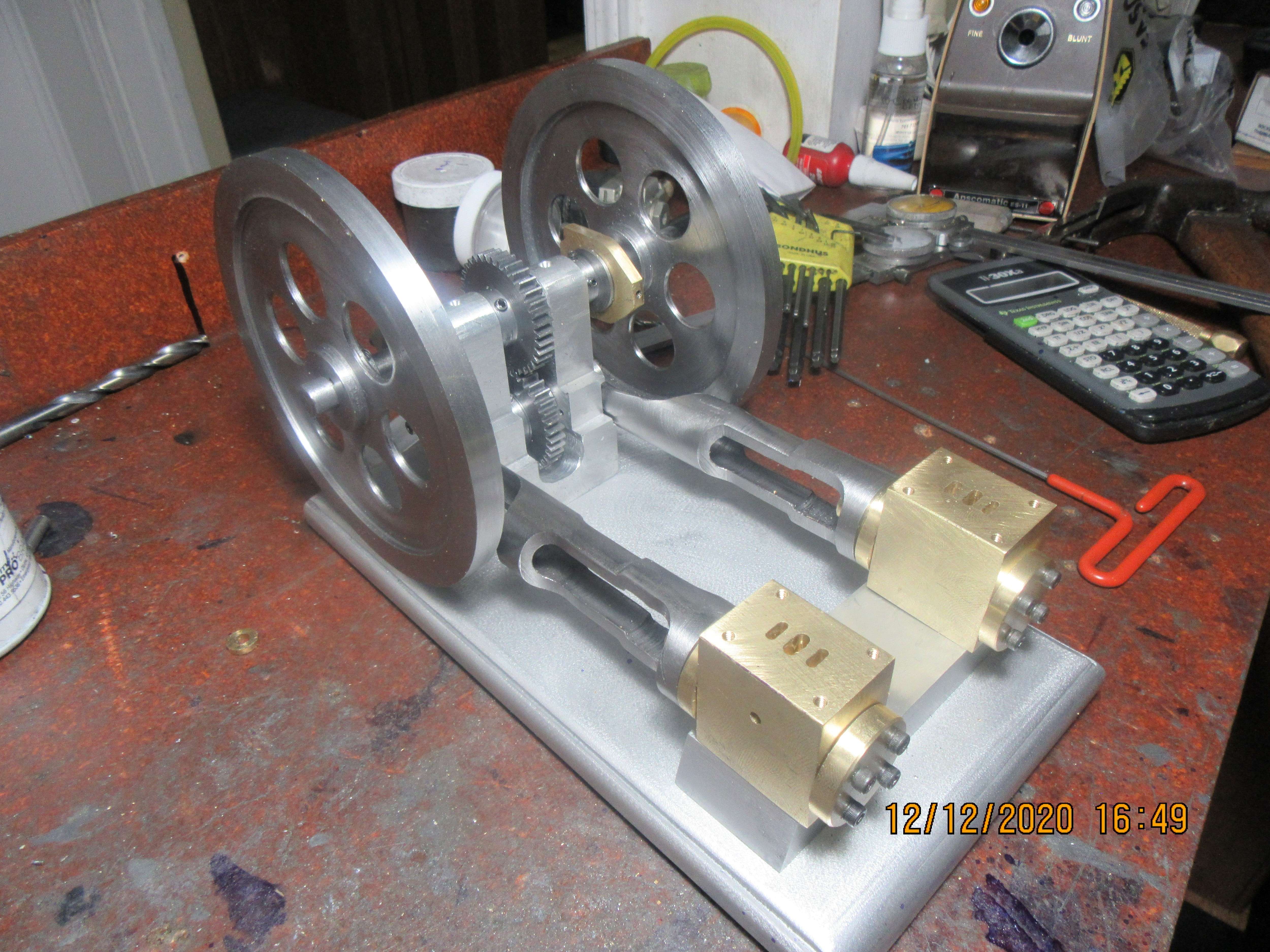
Putting in the physics that Brian leaves out, and hopefully not confusing things too much: the moment of inertial is proportional to mass times radius squared, where radius is the distance of that mass from the center of the circle. After a whole lot of math (or cheating by looking at tables, and a little bit of math), you find that a flywheel with all of its mass concentrated on the rim is twice as effective for the weight as one that's just a flat disk. If I'm guessing right, Brian's flywheel probably has a moment of inertia about 60% higher for its mass than if he'd used a bit thinner stock and made it perfectly flat.
 
Tomorrow, after I completely finish the crankshaft, I will work on the eccentrics and eccentric straps. In the past I have made one piece eccentric straps and a two piece eccentric to hold the straps in place. That works, but it requires rework to a standard socket head cap-screw to make everything fit into a small area. I'm going to do something a little different here. I will make the eccentric from one piece with a flange on each side to keep the eccentric strap in place. The eccentric strap will be two piece with #4 capscrews holding the two halves together. With this design I can use a standard #4 shcs with no modification, and the eccentric strap ends up being much simpler to machine.
zlefRh.jpg
Hi Brian, I have just seen your eccentric strap design. Very neat and conventional. But maybe you can teach me the merits of
1) the cap screws going from the cap into threads in the body - instead of the other way around?
2) using tapped threads in the eccentric strap instead of through holes and nuts? (I used holes with through bolts and nuts on a table engine eccentric - just seemed simple that way?).
3) Are the 2 halves of the eccentric strap dowelled - I guess too small for that so does the eccentric naturally align the 2 halves when tightening cap screws? Or is there a close fit of the shank of the cap screw in the through hole to determine mutual alignment of the halves?
4) My friend made his eccentric strap - for a steam Mill engine - but split along the axis of the eccentric rod. I.E. perpendicular to the split-line you (conventionally) have. Would there be any disadvantage doing it his way? - He was using material from his scrap bin and he thought it would be a talking point!
Is the eccentric mass significant when balancing the crankshaft? - I must admit I haven't thought of this till just now, but as it will be near 90 degrees from the crank it may off-set side oscillations of the con-rod - I think? - Or does it make it worse? - I need to have another look at your gear arrangement and twin shafts to work it out - unless you already have a CAD section that shows the shafts, rods and gears?
I'm just curious - and willing to learn.
Thanks, I'm enjoying your build and the work you are presenting. A good tutorial!
K2
 
Thanks Brian for taking the time to post those. i have a pointed end mill like number 3 and have seen the ball nose mills like number 1 but have never seen the roundover bit like number 2. ill have to shop around for some. but wanted to say thank you for show them. have seen some use router bits but was always afraid to try it. need to get one and try on a little scrap aluminum or something
Hi Wereowance. Not sure if it will help... but: When I did a job as Workshop Manager for a short-term welding and machine shop making busbars and connections for and Aluminium Smelter contract... we needed to machine aluminium bars (8" x 2" and a couple of feet long) 45 degrees before welding on the "flexible" connector (made from a pack of 1mm aluminium sheets). The aluminium was soft "99% pure electrical grade". We used a woodworking machine that would go up to 20,000rpm and used woodworking bits in the flycutter. (4in diameter?), The swarf (wire wool) flew! Also we used the same flycutter arrangement to machine 8" wide flat surfaces in 2 passes on bars that were drilled as the pads for the electrical bolted joints. - The only problem we had was clearing the volume of swarf.... The woodworking shop that sold us the machine had a suction dust collector - The aluminium swarf ("candy-floss") we produced had to be manually cleared and compressed and still filled huge volumes for little weight of scrap.
So maybe woodworking tools at high speed will work for you?
Do tell...
K2
 
Ssteamchick--eccentric straps are not pinned. They fit between two flanges on eccentrics and can't move. The advantage of having the bolts set up the way I do is that the heads end up resting against a flat surface. The bolt heads are almost as wide as the eccentric straps, so they can't be counterbored. If the split was 90 degrees to the way I have it, every time the rod came under pressure or tension the forces would bear directly on the split, and I don't think that would be good. and yes, there is a very close fit between the cap screws and the eccentric straps.
 
Thanks Brian, a logical explanation.
I worked on HV circuit breaker design in the 1980s. An Engineering Professor from the local university advised on finit element analysis they had been doing (rare in those days) and advised that typical rod ends should have the following "simple rules" applied. (1) Adequate side material to take the dynamic forces in tension applied to the bottom-half of the bearing. In the case of your eccentric that is the tensile force and stresses in the bolts. (2) adequate stiffness of the "beam" section of the bottom half of the bearing, considered as a simple beam - in the case of your eccentric end "bottom cap" that would be a beam of section of the cap, between the 2 bolt centres and loaded at the centre.
I guess the loads of the valve on the eccentric are really tiny, and the eccentric relatively large by comparison, so the design is more than adequate, however configured.
On my friend's longitudinally split eccentric cap, the tensile forces at the sides are contained in the brass of the eccentric strap but the stiffness of the end of the eccentric strap is ensured by the clamping force of the steel bolt at that point, and the 2 clamped faces of the eccentric strap. In terms of the split point being at point of maximum bending moment, I guess the design is not the best - or stiffest - but is adequate for his model - a scratch built version of a Stuart no. 1. Vertical DA single.
A new observation - for discussion: The flywheel is like the solid disc flywheel common on many traction engines, road rollers etc. How will you balance this against the crank-shaft and eccentrics? I know how to do the calculations, (a bit of fun in your case of 2 cranks at 90 degrees, plus eccentrics rotating in the opposite direction?) but I was wondering if you were going to bolt-on counter-balance weights, or drill holes or something to remove metal from the opposite side? I think curved brass counterweights against the bright steel could look quite attractive? - with tiny steel bolts securing them? I have seen cast spoked flywheels on models that have been drilled on the outside of the rim and it just doesn't look so good to me.
Excellent work you do.
Thanks
K2
 
If you choose to do such - - - please don't machine to within a 'few thou' - - - - that won't leave you with enough to remove to give you 'good' parts.
I would suggest somewhere between 30 and 50 thou and even then I would be using 2 cuts - - - -you know - - - just in case. (Murphy tends to be a regular visitor when I'm around - - - - grin!)
Yes, thank you, I would not remove the part from the chuck at all for 'only a few thou', that's what I meant, what you said.
 
Hi Brian, I have just seen your eccentric strap design. Very neat and conventional. But maybe you can teach me the merits of
1) the cap screws going from the cap into threads in the body - instead of the other way around?
2) using tapped threads in the eccentric strap instead of through holes and nuts? (I used holes with through bolts and nuts on a table engine eccentric - just seemed simple that way?).
3) Are the 2 halves of the eccentric strap dowelled - I guess too small for that so does the eccentric naturally align the 2 halves when tightening cap screws? Or is there a close fit of the shank of the cap screw in the through hole to determine mutual alignment of the halves?
4) My friend made his eccentric strap - for a steam Mill engine - but split along the axis of the eccentric rod. I.E. perpendicular to the split-line you (conventionally) have. Would there be any disadvantage doing it his way? - He was using material from his scrap bin and he thought it would be a talking point!
Is the eccentric mass significant when balancing the crankshaft? - I must admit I haven't thought of this till just now, but as it will be near 90 degrees from the crank it may off-set side oscillations of the con-rod - I think? - Or does it make it worse? - I need to have another look at your gear arrangement and twin shafts to work it out - unless you already have a CAD section that shows the shafts, rods and gears?
I'm just curious - and willing to learn.
Thanks, I'm enjoying your build and the work you are presenting. A good tutorial!
K2
Steam,
Could you clarify your first point? The others I get but the first is, unclear?
 
Was I busy today??---Yes, you can bet your bippy that I was. 32 holes drilled and tapped, bore and air passages machined in. I've been at these cylinders all day, and I'm going upstairs to set with my good wife and drink rum now!!!
R1oB17.jpg
 
Steamchick---Simple answer--I don't balance them. This is a low rpm model engine. There is a way to calculate the required balancing weights, but it is complex and requires a very sensitive weigh scale that I don't have.
 
Was I busy today??---Yes, you can bet your bippy that I was. 32 holes drilled and tapped, bore and air passages machined in. I've been at these cylinders all day, and I'm going upstairs to set with my good wife and drink rum now!!!
R1oB17.jpg
Whoa! Such beautiful progress. At this rate, you will be done shortly and have it puffing away.
 
Steamchick---Simple answer--I don't balance them. This is a low rpm model engine. There is a way to calculate the required balancing weights, but it is complex and requires a very sensitive weigh scale that I don't have.

Ahh -- for infernal combustion 2-strokes, the rule of thumb is to put half the reciprocating weight on the crank pin, and then balance the assembly. If you don't hit it exactly, you just remember that your motor can't be perfectly balanced anyway.

(But aside from having a nifty counterweight incorporated into the flywheel, I like your method of just observing it's low speed).
 
This morning I whittled out a pair of steam-chests. The steam-chest covers will be machined from mild steel and painted to match the flywheels.
chulH5.jpg
I'm just curious about where y;oou get all that brass? I have about 200 lbs of the stuff in containers waiting to be made into ingots or cast that I have had for a couple decades becauise the stuff is so expensive but easily (relatively) melted. Do you have a cheap source?
 
There is no cheap source for brass. I buy my brass from a metal supplier right here in Barrie, but I cry a little bit every time that I do.
 
There is no cheap source for brass. I buy my brass from a metal supplier right here in Barrie, but I cry a little bit every time that I do.
Well, eventually, I am going to get my foundry set up and melt down this alu and brass into ingots, and I hope, a couple casts. Im wondering if you know anything about melting alu and brass. I know alu one can use soda or buy commercial gas removers (apparently hydrogen) and slag materials but I don't know about brass. I would thimk it too would have some kind of gas remover, can one use the same stuff as with alu? Have you done foundry work?
 
This morning I whittled out a pair of steam-chests. The steam-chest covers will be machined from mild steel and painted to match the flywheels.
chulH5.jpg
Hi Brian, you are progressing well with this engine. Looking good! Will the inside of the MS valve covers have any anti- corrosion on them? Do you run steam? Or just compressed air? As most of my models are cast iron, and I run steam, I always have to wash-out the wet with lots of WD40, then oil with steam oil after running. Just time consuming maintenance... I have seen a valve chest cover (removed) which was painted inside, but not on the joint faces, as the slide valve didn't contact the cover. Seemed to work OK? I was wondering about copper plating? Phosphating? Or tinning? (I have lots of spare plumbers lead solder?). I'll be glad of "easy" suggestions?
 
Steamchick--I run my engines on compressed air. Occasionally I give a squirt of light oil into the airline, knowing it will lubricate the slide-valve and the piston. I never wash my engines out after I've run them. I don't put any coatings on my slide valve nor my cylinders. In this particular case I am making the cylinders from brass and the slide valve from mild steel, simply to avoid the galling of running two identical metals together.----Brian
 
Today was the day to make slide valves and control rods. I dug around in my "scrap brass drawer" and actually found a little bit of bronze to make the rod ends out of. The slide valves and control rods are cold rolled steel. The cross nuts in the slide valves are cold rolled steel. That's enough work for today.
BInBa3.jpg
 
Back
Top